Advertisement
Quick Links
Advertisement

Related Manuals for Insportline IN 4071 Verge


Summary of Contents for Insportline IN 4071 Verge
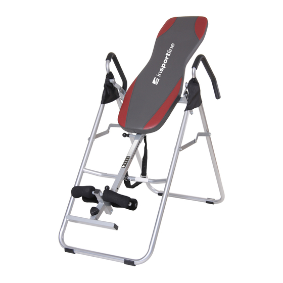
- Page 1 Owner’s manual – EN IN 4071 Inc inSPORTline Verge...
- Page 2 Parts Listing The following parts list describes all of the parts illustrated on the exploded diagram on the following page. Please note, most of these parts are already pre- assembled on your unit. Part# Description Part# Description Front Leg Tube Hex Bolt (M10x30 mm) 02A-R Right Cross Support Bracket Hex Bolt (M6x50 mm)
- Page 3 Exploded Diagram The following diagram is provided to help you familiarize yourself with the parts and hardware that will be used during the assembly process. Please note that not all of the parts and hardware you see here will be used while you are assembling the machine because some of these items are already pre-installed.
-
Page 4: Assembly Instructions
Assembly Instructions A s s e m b l y S t e p 1 A.) A-Frame Assembly Open the pre assembled A-Frame, which is composed of parts (#01), (#02A-R/L) and (#03A). Make sure that two Cross Support Brackets (#02A-R/L) are fully extended and firmly locked in place by pressing down on them. - Page 5 Assembly Instructions A s s e m b l y S t e p 2 A.) Cover Assembly Slide the Left Cover (#15L) and Right Cover (#15R) onto the left and right of the Hand Rail (#13R/L). B.) Adjustable Pivot Bar Assembly Each Adjustable Pivot Bar (#06) has three adjust able holes in it.
- Page 6 Assembly Instructions A s s e m b l y S t e p 3 A.) Adjustable Ankle Brace Assembly Take the illustrated assembly which is composed of parts (#04),(#05A) and (#18) out of the box. Pull up the Ankle Brace Lock Pin (#18) as illustrated and, at the same time, pull the Adjustable Ankle Brace (#04) out of the Height Adjustment Tube (#05A) SLOWLY.
- Page 7 Assembly Instructions A s s e m b l y S t e p 4 A.) Foam Roller Assembly Slide the two Foam Rollers (#20) onto the Adjustable Ankle Brace (#04) and another two on the Ankle Brace Tube (#12). Apply soapy water to the tubes if the foam rollers do not slide on easily.
- Page 8 Safety Instructions WARNING: 250 lb. WEIGHT CAPACITY DO NOT USE THIS INVERSION TABLE WITHOUT A PHYSICIAN'S APPROVAL IF YOU HAVE ANY OF THE FOLLOWING CONDITIONS (this list is for reference only, it is not an exhaustive listing): Pregnancy, Hiatal Hernia, Ventral Hernia, Glaucoma, Retinal Detachment or Conjunctivitis; High Blood Pressure, Hypertension, recent Stroke or Transient Ischemic Attack;...
- Page 9 Usage Guidelines ATTACH THE SAFETY STRAP TO THE NYLON COVERED STEEL FRAME. The buckle of the Safety Strap should be positioned about KDOIZD\ down the Strap with the concave side facing up. The two ends of the buckle should show; the middle slot should be covered up by the Strap. Feed the free end of the Strap through the buckle under one end, over the middle and under the other end.
- Page 10 Usage Guidelines The settings for height range from 4'7" (140cms) to 6'5" (196cms). To adjust the Inversion Table for the correct height setting; Pull out the Height Selector Lock Pin (#19) and slide the Height Adjustment Tube (#05A) until the desired height is shown just below the sleeve.
-
Page 11: Usage Guidelines
Usage Guidelines Follow these instructions in order to confirm that you have the correct settings. When you lie down with both arms across your chest the Inversion Table should rotate a few inches UPWARD. If the Inversion Table does not move or if it tilts all the way back, the settings are incorrect. - Page 12 Usage Demo I. Starting Position: II. With One Arm Half Raised: III. With One Arm Fully Raised: IV. With Both Arms Raised: V. Fully Inverted:...
Need help?
Do you have a question about the IN 4071 Verge and is the answer not in the manual?
Questions and answers