Table of Contents
Advertisement
Advertisement
Table of Contents

Related Manuals for DeVilbiss FLG3


Summary of Contents for DeVilbiss FLG3
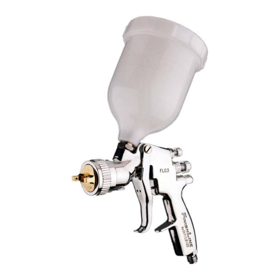
- Page 1 SB-E-2-609 OPERATION MANUAL FLG3 —HVLP Gravity Spraygun P 1 - 8...
-
Page 2: Ec Declaration Of Conformity
We: ITW Finishing UK, Ringwood Rd, Bournemouth, Dorset, BH11 9LH, UK, as the manufacturer of the Spraygun model FLG3, declare, under our sole responsibility, that the equipment to which this document relates is in conformity with the following standards or other normative documents: BS EN 292-1 PARTS 1 &... -
Page 3: Safety Warnings
SAFETY WARNINGS sprayed. Fire and explosion Always wear eye protection when Solvents and coating materials spraying or cleaning the spraygun can be highly flammable or Gloves must worn when combustible when sprayed. ALWAYS s p r ay i ng c le a ni n g th e refer to the coating material suppliers equipment... -
Page 4: Parts List
Parts List Ref. No Description Part Number Air Cap Retaining ring FLG-301 Aircap No3 FLG-1-3 Fluid Tip Fluid Tip Seal (kit of 5) FLG-304-K5 Fluid Tip and Seal Kit See Below Baffle FLG-305 Cup Gasket Spreader Valve Seal Bushing Seal, Bushing, Spring and Knob Kit Fluid Needle FLG-311 * 13... -
Page 5: Specification
Specification Air supply connection - Universal BSP and Maximum static inlet pressure - = 12 bar (175 psi) Nominal gun inlet pressure with gun triggered - 1.6 bar (23 psi) Maximum Service temperature - 40°C Gun Weight - 530 g Materials of Construction Gun body Aluminium... -
Page 6: Installation
Installation electrical bond from the spraygun to Important: To ensure that this equipment earth should be checked with an reaches first class condition, ohmeter. A resistance of less than protective coatings have been use. Flush Ω is recommended. the equipment through with a suitable solvent before use. -
Page 7: Replacement Of Parts
Replacement of Parts Nozzle (3) and Needle (12) – Remove spanner sufficient to seal but to allow parts in the following order: 14, 13, 12, free movement of needle. Lubricate with 1, 2 and 3. Examine the seal (4) and gun oil. - Page 8 ITW Finishing Systems and Products Ringwood Road, Bournemouth, BH11 9LH, England. Tel. No. (01202) 571111 Telefax No. (01202) 581940, Website address http://www.itweuropeanfinishing.com ITW Oberflächentechnik GmbH & Co. KG Justus-von-Liebig-Straße 31 63128 Dietzenbach Tel (060 74) 403-1 Telefax: (060 74) 403300 Website address http://www.itw-finishing.de ITW Surfaces Et Finitions 163-171 avenue des Auréats B.P.
Need help?
Do you have a question about the FLG3 and is the answer not in the manual?
Questions and answers