Table of Contents
Advertisement
Quick Links
Download this manual
See also:
Operating Manual
Advertisement
Table of Contents

Related Manuals for DeVilbiss FLG-P5-14


Summary of Contents for DeVilbiss FLG-P5-14
- Page 1 SB-E-2-792 ISS.04 Operation Manual FLG-P5-14 Transtech Pressure-feed Spray Gun...
-
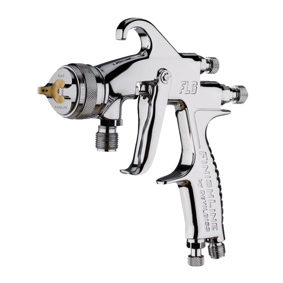
Page 2: Flg5 - Pressure-Feed Spray Gun
II 2 G X. Suitable for use in Zones 1 and 2 Important: These spray guns are suitable for use with solvent-based coating materials. The design uses EPA compliant atomising (Devilbiss Trans-Tech®) technology to reduce overspray and improve coating efficiency. Nozzles and needles are manufactured in stainless steel. These... -
Page 3: Specification
Specification Air supply connection - Universal ¼” BSP and NPS Maximum static air inlet pressure - = 12 bar (175 psi) Nominal gun inlet pressure with gun triggered - 2.4 bar (35 psi) Maximum service temperature - 40°C Gun weight - 930 g Air flow - 277 l/min (9.8 cfm) - Page 4 Fire and explosion Solvents and coating materials can be highly flammable or combustible when sprayed. ALWAYS refer to the coating material suppliers instructions and COSHH sheets before using this equipment. Users must comply with all local and national codes of practice and insurance company requirements governing ventilation, fire precautions, operation and house-keeping of working areas.
-
Page 5: Parts List
Parts List Ref. No Part Number Description 1 SGK-0023 Retaining ring 2 FLG-0001-622 Air cap No 622 3 SGK-0012-14 Fluid tip 1.4mm «● 4 - Gasket ● 5 K-5032 Sprayhead Kit « Packing Packing gland nut Circlip Spray pattern adjustment valve bushing 10 - Spray pattern valve «... -
Page 6: Preventative Maintenance
Preventative Maintenance 1. Turn off air and coating supply and relieve pressure in the supply lines, or if using QD system, disconnect from airline and fluid line. 2. Remove air cap (1) & (2) and clean. If any of the holes in the cap are blocked with coating material use a toothpick to clean. -
Page 7: Replacement Of Parts
Replacement of Parts Nozzle (3) and needle (16) – Remove parts in the following order: 18, 17, 16, 1, 2 and 3. Check condition of nozzle seal (4) and replace if necessary. Replace any worn or damaged parts and re-assemble in reverse order. Recommended tightening torque for nozzle (3) 16-20 Nm (150- 180 lbf in). - Page 8 ITW Finishing Systems and Products Ringwood Road, Bournemouth, BH11 9LH, England. Tel. No. (01202) 571111 Telefax No. (01202) 581940, Website address http://www.itweuropeanfinishing.com ITW Finishing Systems and Products is a Division of ITW Ltd. Reg. Office: Admiral House, St Leonard’s Road, Windsor, Berkshire, SL4 3BL,...
Need help?
Do you have a question about the FLG-P5-14 and is the answer not in the manual?
Questions and answers