Table of Contents
Advertisement
Sig Mfg. Co., Inc...401-7 South Front Street...PO Box 520....Montezuma, IA 50171-0520
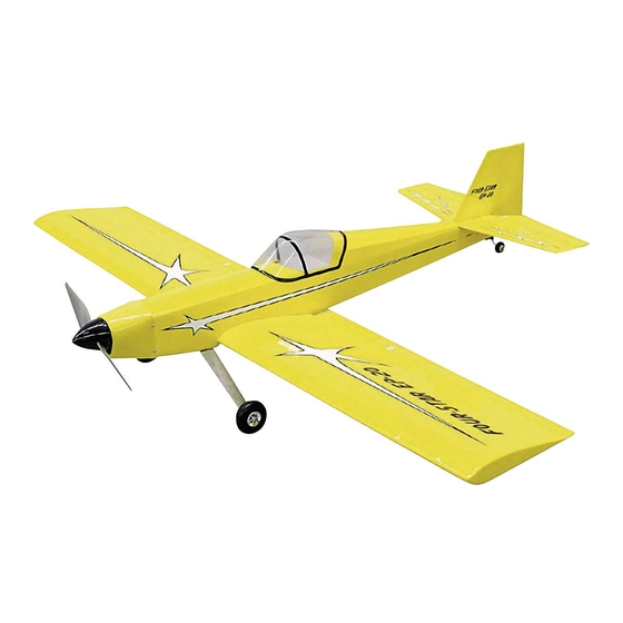
Congratulations on your purchase of the SIG FOUR-STAR 20EP. For many years the SIG Four-Star series of low-wing sport
airplanes have proven to be among the most popular and versatile at the flying field. Originally designed for 2-stroke glow
engines, Four-Stars have also excelled with 4-stroke, gasoline, and now electric motors. The secret to their popularity is their
light flying weight and low wing loading, combined with excellent aerobatic performance. The maneuverability and smooth
handling of the Four-Star will make it the sport model you'll want to take to the flying field every time.
The FOUR-STAR 20EP is the first Four-Star kit designed primarily for electric power (although the structure is configured to
easily accommodate a glow engine if you wish to go that way). This use of a modern electric power system in the legendary
Four-Star has produced a marvelous little R/C ship that is a pure joy to fly. It's small enough to carry around in your vehicle
completely assembled and ready to fly almost anywhere, anytime!
Assembly of the FOUR-STAR 20EP is quick and easy, following the detailed instructions in this manual. All parts are CAD-
drawn and the majority are laser-cut, so that everything fits the way it should! We strongly suggest that you read through the
manual first to get familiar with the various parts and the assembly sequences.
Advertisement
Table of Contents

Related Manuals for SIG Four-Star 20EP


Summary of Contents for SIG Four-Star 20EP
- Page 1 Assembly of the FOUR-STAR 20EP is quick and easy, following the detailed instructions in this manual. All parts are CAD- drawn and the majority are laser-cut, so that everything fits the way it should! We strongly suggest that you read through the...
-
Page 2: Covering Material
4-CHANNEL RADIO CONTROL SYSTEM with 4 SERVOS "Standard" size radio gear is not recommended for an airplane as small as the Four-Star 20EP. The Four-Star gets its great flight performance from many factors, but two of the most important factors are its light weight and generous wing area. - Page 3 GLUES Choice depends a lot on you personal preference. We used Thin, Medium, and Thick SIG CA; CA Accelerator; Fine point CA applicator tips; and SIG Epoxy Glue (5-minute and 30-minute). BASIC MODELING TOOLS Screwdrivers, Pliers (regular, needle nose, flat nose), Wire Cutters, Scissors,...
- Page 4 The laser cut balsa and plywood parts can be identified using the "KEY TO LASER CUT PARTS". Mark the identification numbers on the corresponding parts before removing them from the laser cut sheets. Leave all the laser cut parts in the sheets until needed in construction.
- Page 6 WING PANEL CONSTRUCTION We will build the wing in separate right and left wing panels, and then join the panels together after they are assembled. Let's start with the LEFT WING PANEL. To get started, tape or pin the wing plan to your building board. Cover the plan with a layer of waxed paper to keep glue from sticking to the plan.
- Page 7 4a. Slip the 1/16"x1-1/2"x24" Balsa Trailing Edge Bottom Sheet in place under the back ends of the wing ribs. Slide it forward against the notches in the bottom of the ribs. Now pin the ends of all the wing ribs to the Trailing Edge Bottom Sheet and firmly to the plan.
-
Page 8: Joining The Wing Panels
14. Cut a 1/2" dia. hole in the top sheeting just behind the main spar. This is for the aileron servo chord to exit the wing panel. 15. Use a large sanding block to sand any excess spar ends and sheeting flush with the W-1 rib. Use a sanding block large enough to sand the entire part at the same time. -
Page 9: Tail Surfaces
22. Drill the center of the leading edge with a 1/4" dia. drill bit until the 1/4"x1-1/2" hardwood dowel can be slid into place in the notches in the W-1 ribs. The dowel should end up protruding about 5/16" out front of the leading edge. When satisfied with the fit, glue the dowel in place. - Page 10 d. Use a sharp #11 hobby knife to cut a groove in the leading edge to accept the Wire Joiner. e. Wipe the Wire Joiner clean with some type of solvent (paint thinner, mineral spirits, rubbing alcohol, etc.), and then glue it into the elevators with epoxy. Be sure to keep the leading edges of the two elevators aligned straight while the glue dries.
-
Page 11: Fuselage Construction
FUSELAGE CONSTRUCTION 31. Remove the balsa Fuselage Sides from laser-cut sheet no. 5 and the FD-1 Doublers from sheet no. 3. Use slow drying glue to laminate one doubler to each fuselage side, making sure to make a LEFT and RIGHT assembly. Also make sure that you have the doublers properly positioned on the fuselage sides - 2 points to pay particular attention to are the wing saddle and the bottom of the nose -... - Page 12 37. Install the balsa fuselage bottom piece FBT-2, gluing it to all its mating parts. 38. Install the plywood TWM tailwheel mount. 39. At the front of the fuselage, carefully lift the front portion of the fuselage top up to fit between the fuselage sides. Remember back in step 34 you cracked the top slightly along the dashed cut lines so it can make this bend, When you have it fitting well between the side, glue together with a few drops of thin CA glue.
- Page 13 46. Glue on plywood top former FHR. Note on the plan that FHR tilts back towards the rear of the fuselage. There should be approx. 2-3/8" between the top of FHR and the top of former F-4T. 47. From 36" long balsa stock, cut to length and glue in place the five 3/32"x3/16" stringers for the top rear of the fuselage. When glue is dry, sand the ends of the stringers flush with the front of former FHR and the rear of former F-6T.
-
Page 14: Surface Preparation
COVERING Any brand of quality iron-on plastic covering material is suitable for the Four-Star 20EP. If the manufacturer has a "lite" version, use it to save a little weight. The color choice and final color scheme is entirely up to your imagination. It... -
Page 15: Decal Application
The soapy water mixture can simply be water mixed with a small amount of dish soap, or SIG Pure Magic Model Airplane Cleaner, or Fantastic®, or Windex®, or 409®... -
Page 16: Hinging The Control Surfaces
Allow the decals to set overnight to finish drying. Once dry, they will be solidly adhered to the model. When completely dry, wash off any soapy smears with a soft clean wet rag. Hinging The Control Surfaces The hinges in this kit are designed to be installed with Thin CA glue. Thin CA (any brand) is the ONLY type of glue that can be used on the hinges - do not use epoxy or any other type of glue! 56. -
Page 17: Final Assembly
i. The rudder is hinged in the same manner as the other parts, but it is easier to install AFTER the fin has been glued onto the fuselage. For now, go ahead and cut the slots for the hinges in the fin and rudder, but do not glue them. Set them aside until later. - Page 18 59a. Install the 3/4" dia. Tailwheel on the axle of the formed Tailwheel Wire, using the 1/16" id Wheel Collar provided. b. Slide the plastic Tailwheel Bracket onto the shank of the tailwheel wire. Be certain that you have the bracket on right side up. c.
-
Page 19: Radio Installation
Radio Installation 65. Mount a Nylon Control Horn on the bottom of the left elevator using two #2 x1/2" Sheet Metal Screws provided, as follows. a. Note that there are right and left Nylon Control Horns. Study the plans and photos carefully to identify which type you should use on each control surface. - Page 20 d. Unhook the rear of the elevator pushrod from the control horn and slide the pushrod as far forward as possible. Cut off the servo end of the pushrod wire at the longest mark. e. Bend the end of the pushrod wire over 90 degrees at the remaining mark (the first mark you made back in step b.) Make the bend as sharp as possible.
-
Page 21: Motor Installation
Motor Installation This section presumes you are installing an electric power system in your Four-Star 20EP. We will show details of our installation of the Maxx Products Himax 3510-1100kv Brushless Outrunner Motor and Motor Mount, along with a 36 amp ESC, and a 3S1P Lipo 1800 mAh Battery Pack. - Page 22 78a. Mount your motor on the firewall with appropriate screws. Be sure to locate the centerline of your motor with the thrust line. b. The motor wires can be fed back through any of the holes in the firewall - whichever one is most convenient for your motor configuration.
-
Page 23: System Tests
e. Remove the cowling from the fuselage. Open up the four holes in the cowling to allow the mounting screws to pass cleanly through the plastic (a #45 .082" drill bit is perfect). f. On the fuselage, run the mounting screws in and back out of the holes a couple times to create good threads in the wood. -
Page 24: Control Throws
The main wing spar of the Four-Star 20EP is located precisely in the middle of this balance range. This means that the simplest way to check the balance of your Four-Star 20EP is to pick up the airplane with a fingertip under the each wingtip at the main spar location. -
Page 25: First Test Flight
First Test Flight The Four-Star 20 is a fun airplane to fly, but it is not a basic trainer. If you have no previous R/C flying experience, we suggest that you not attempt to fly this model without the assistance of an experienced R/C pilot. Contact your local R/C club or ask your hobby dealer for the names of good fliers in your area and a suitable location for flying. -
Page 26: Customer Service
Customer Service SIG MFG CO. is totally committed to your success in both building and flying the FOUR-STAR 20EP design. Should you encounter any problem building this kit, or discover any missing or damaged parts, please feel free to contact us by mail or telephone.
Need help?
Do you have a question about the Four-Star 20EP and is the answer not in the manual?
Questions and answers