Table of Contents
Advertisement
Quick Links
Advertisement
Table of Contents

Subscribe to Our Youtube Channel
Related Manuals for KTM 525 XC ATV EU


Summary of Contents for KTM 525 XC ATV EU
- Page 1 OWNER'S MANUAL 2010 525 XC ATV EU Art. no. 3211487en...
- Page 3 DEAR KTM CUSTOMER Congratulations on your decision to buy a KTM ATV. You are now the owner of a state-of-the-art sports ATV that will give you enormous DEAR KTM CUSTOMER pleasure if you service and maintain it accordingly. We wish you a lot of enjoyment in riding this vehicle! Enter the serial numbers of your vehicle below.
- Page 4 Reproduction, even in part, is permitted only with the express written permission of the copyright owner. ISO 9001(12 100 6061) According to the international quality management standard ISO 9001, KTM uses quality assurance processes that lead to the maximum possible quality of the products.
-
Page 5: Table Of Contents
TABLE OF CONTENTS Tripmaster switch ............. 29 TABLE OF CONTENTS MEANS OF REPRESENTATION ..........7 Setting kilometers or miles ..........29 IMPORTANT INFORMATION ........... 8 Setting the clock .............. 30 VIEW OF VEHICLE..............12 Adjusting the speedometer functions........31 View of the vehicle from the left front (example) ....12 Querying the lap time ............ - Page 6 Important maintenance work to be carried out by an Checking rear sprocket / engine sprocket for wear ....101 authorized KTM workshop (as an additional order) ....69 Checking chain wear ............102 Important checks and maintenance work to be carried out Adjusting chain tension...........
- Page 7 TABLE OF CONTENTS Installing the front trim ........... 142 Removing front brake linings ........111 Removing the rear fender ..........142 Mounting front brake linings ........112 Installing the rear fender ..........144 Changing the front brake linings ......... 113 Removing the engine guard ..........
- Page 8 TABLE OF CONTENTS CLEANING................. 178 Cleaning the vehicle ............178 STORAGE ................180 Storage................180 Putting the vehicle into operation after storage ....181 TECHNICAL DATA - ENGINE ..........182 Capacity - engine oil ............183 Capacity - coolant............183 TECHNICAL DATA - ENGINE TIGHTENING TORQUES...
-
Page 9: Means Of Representation
All work marked with this symbol requires specialist knowledge and technical understanding. In the interest of your own safety, have these jobs performed at an authorized KTM workshop! There, your vehicle will be serviced optimally by specially trained experts using the specialist tools required. -
Page 10: Important Information
Spare parts, accessories For your own safety, only use spare parts and accessories that have been approved and/or recommended by KTM and have them installed by an authorized KTM workshop. KTM accepts no liability for other products and any resulting damage or loss. - Page 11 IMPORTANT INFORMATION The current KTM PowerParts for your vehicle can be found on the KTM website. International KTM Website: http://www.ktm.com Work rules Special tools are needed for certain tasks. They are not included with the vehicle but can be ordered under the number in parentheses.
- Page 12 A professional trainer will show you how to handle your ATV safely in various riding situations and on different terrain. Your KTM dealer will be glad to advise you. Warning notes Be sure to pay attention to the notes and warnings given here.
- Page 13 IMPORTANT INFORMATION Grades of risks Danger Danger that leads immediately and certainly to severe and permanent injury or death. Warning Danger that will probably lead to severe and permanent injury or death. Note Danger of serious damage to machine or material. Warning Risk of environmental damage.
-
Page 14: View Of Vehicle
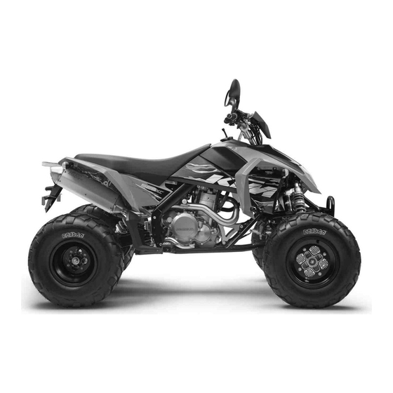
VIEW OF VEHICLE View of the vehicle from the left front (example) 601023-10... - Page 15 VIEW OF VEHICLE Hand brake lever Fuse box Headlight Front left turn signal Front bumper Steering lock Front left shock absorber Clutch lever Emergency OFF switch with rip cord Heel protector Left footrest Shift lever Outside brake disk guard...
-
Page 16: View Of The Vehicle From The Right Rear (Example)
VIEW OF VEHICLE View of the vehicle from the right rear (example) 601039-10... - Page 17 VIEW OF VEHICLE Light switch, turn signal switch, kill switch, horn button Electric starter button Parking brake lever Filler cap Main silencer License plate holder Rear shock absorber Rear sprocket with chain Rear brake Foot brake lever Oil level viewer Fuel tap Throttle lever Ignition switch...
-
Page 18: Location Of Serial Numbers
LOCATION OF SERIAL NUMBERS Chassis number The chassis number is stamped on the right side of the frame in the vicinity of the upper control arm. 100002-10 Type label The type label is located on the frame tube on the right in front of the radiator. ... -
Page 19: Key Number
LOCATION OF SERIAL NUMBERS Key number The key number is indicated on the KEYCODECARD. Info You need the key number to order a replacement key. Keep the KEYCODECARD in a safe place. 100089-10 Engine number The engine number is stamped on the left side of the engine under the engine sprocket. ... -
Page 20: Front Shock Absorber Part Number
LOCATION OF SERIAL NUMBERS Front shock absorber part number The shock absorber part number is stamped on the top part of the shock absorber. 601024-10 Rear shock absorber part number The shock absorber part number is stamped on the top part of the shock absorber. ... -
Page 21: Controls
CONTROLS Clutch lever The clutch lever is fitted on the left side of the handlebar. Possible states Clutch lever in neutral position – In this position, the engine is force-locked with the • gear and the starting circuit is interrupted. The electric starter does not turn over when the electric starter button is pressed. -
Page 22: Hand Brake Lever, Front Parking Brake
CONTROLS Hand brake lever, front parking brake The hand brake lever is located on the right side of the handlebar and operates the front brakes. The hand brake lever is combined with the front parking brake, which locks the front wheels to prevent the vehicle from rolling away. -
Page 23: Steering Lock
CONTROLS Steering lock The steering lock is fitted on the steering column. The steering lock can be used to lock the steering. This makes steering impossible and the vehicle cannot be ridden. 601046-10... -
Page 24: Parking Brake Lever
CONTROLS Parking brake lever The parking brake lever is located on the left side of the handlebar and operates the rear brakes. The parking brake lever is combined with the parking brake, which locks the rear wheels to prevent the vehicle from rolling away. To apply the parking brake, fold down the parking brake lever. -
Page 25: Throttle Lever
CONTROLS Throttle lever The throttle lever is fitted on the right side of the handlebar. The throttle lever is used to control the engine speed. 100007-10 Light switch The light switch is fitted on the left side of the handlebar. ... -
Page 26: Turn Signal Switch
CONTROLS Turn signal switch The turn signal switch is fitted on the left side of the handlebar. Possible states Turn signal off – The turn signal switch is in the central position. Left turn signal on – The turn signal switch is rocked to the left. Right turn signal on –... -
Page 27: Horn Button
CONTROLS Horn button The horn button is fitted on the left side of the handlebar. Possible states • Horn button in basic position pressed – In this position, the horn is actuated. • Horn button 601030-10 Ignition switch 5.10 The ignition switch is located to the right of the speedometer. -
Page 28: Electric Starter Button
CONTROLS Electric starter button 5.11 The electric starter button is fitted on the left side of the handlebar. Possible states • Electric starter button in basic position Electric starter button pressed – In this position, the electric starter is actuated. •... -
Page 29: Indicator Lamp Overview
CONTROLS Indicator lamp overview 5.13 Possible states – No function. Reverse gear indicator lamp flashes green with the flashing rhythm – The Turn signal indicator light turn signal is switched on. lights up blue – The high beam is switched High beam indicator lamp ... -
Page 30: Speedometer
CONTROLS Speedometer 5.15 – Press the key to change the display mode or change to one of the Setup menus. – Press the key to control different functions. – Press the key to control different functions. Info When the vehicle is delivered, only the SPEED/H and SPEED/ODO display modes are activated. -
Page 31: Tripmaster Switch
CONTROLS WS (wheel size) After the display function test, the wheel size WS is displayed briefly. Info 1735 mm corresponds to a circumference of 10" for the front wheels with series tires. After this, the display changes to the mode selected last. 400740-01 Tripmaster switch 5.17... -
Page 32: Setting The Clock
CONTROLS – briefly and repeatedly until H appears at the bottom right of the dis- Press the button play. – Press the button for 3 - 5 seconds. The setup menu is displayed and the active functions shown. – repeatedly until the Km/h/Mph display flashes. Press the button Km/h adjusting –... -
Page 33: Adjusting The Speedometer Functions
CONTROLS – briefly and repeatedly until CLK appears at the bottom right of the Press the button display. – Press the button for 3 - 5 seconds. The hour display flashes. – Set the hour display with the button and/or button –... -
Page 34: Querying The Lap Time
CONTROLS – briefly and repeatedly until H appears at the bottom right of the dis- Press the button play. – Press the button for 3 - 5 seconds. The Setup menu is displayed and the activated functions are shown. – Change to the desired function by pressing the button briefly. -
Page 35: Display Mode Speed (Speed)
CONTROLS Condition The vehicle is stationary. – Press the button briefly and repeatedly until LAP appears at the bottom right of the display. – Press the button briefly. LAP 1 appears on the left side of the display. – Laps 1-10 can be displayed by pressing the button –... -
Page 36: Display Mode Speed/H (Operating Hours)
CONTROLS Display mode SPEED/H (operating hours) 5.23 Condition • The vehicle is stationary. – Press the button briefly and repeatedly until H appears at the bottom right of the dis- play. In display mode H, the operating hours of the engine are displayed. The service hour counter stores the total riding time. -
Page 37: Display Mode Speed/Clk (Clock)
CONTROLS Display mode SPEED/CLK (clock) 5.24 – Press the button briefly and repeatedly until CLK appears at the bottom right of the display. The time is displayed in CLK display mode. Press the button No function Press the button No function Press the button The display changes to the Setup menu of the clock. -
Page 38: Display Mode Speed/Odo (Odometer)
CONTROLS Press the button Next display mode briefly. Display mode SPEED/ODO (odometer) 5.26 – Press the button briefly and repeatedly until ODO appears at the bottom right of the display. In ODO display mode, the total number of kilometers ridden is displayed. Press the button No function Press the button... -
Page 39: Display Mode Speed/Tr2 (Trip Master 2)
CONTROLS Press the button The TR1, A1 and S1 displays are reset to 0.0. for 3 - 5 seconds. Press the button Next display mode briefly. Display mode SPEED/TR2 (trip master 2) 5.28 – Press the button briefly and repeatedly until TR2 appears at the top right of the dis- play. -
Page 40: Display Mode Speed/A1 (Average Speed 1)
CONTROLS Display mode SPEED/A1 (average speed 1) 5.29 – Press the button briefly and repeatedly until A1 appears at the top right of the dis- play. A1 (average speed 1) shows the average speed calculated on the basis of TR1 (trip mas- ter 1) and S1 (stop watch 1). -
Page 41: Display Mode Speed/S1 (Stop Watch 1)
CONTROLS – Press the button for 3 - 5 seconds. Press the button Next display mode briefly. Display mode SPEED/S1 (stop watch 1) 5.31 – Press the button briefly and repeatedly until S1 appears at the top right of the dis- play. -
Page 42: Display Mode Speed/S2 (Stop Watch 2)
CONTROLS Display mode SPEED/S2 (stop watch 2) 5.32 – Press the button briefly and repeatedly until S2 appears at the top right of the dis- play. S2 (stop watch 2) is a manual stop watch. If S2 is running in the background, the S2 display flashes in the speedometer display. Starts or stops S2. - Page 43 CONTROLS Table of functions Display Press the button Press the button Press the button for 3 - Press the button briefly. 5 seconds. Display mode SPEED/TR1 No function No function The TR1, A1 and S1 dis- Next display mode (trip master 1) plays are reset to 0.0.
-
Page 44: Opening Filler Cap
CONTROLS Table of conditions and menu activation Display The vehicle is sta- Menu can be acti- tionary. vated Display mode SPEED/S2 (stop watch 2) • Opening filler cap 5.33 – Press release button , turn filler cap counterclockwise and lift it free. ... -
Page 45: Locking The Steering
CONTROLS Locking the steering 5.35 Note Danger of damage The parked vehicle may roll away or fall over. – Always place the vehicle on a firm and even surface. – Park the vehicle. – Turn the handlebar all the way to the left. –... -
Page 46: Fuel Tap
CONTROLS Fuel tap 5.37 The fuel tap is on the right of the fuel tank. With the tap handle on the fuel tap, you can open or close the supply of fuel to the car- buretor. Possible states Fuel supply off OFF – No fuel can flow from the tank to the carburetor. •... -
Page 47: Choke
CONTROLS Choke 5.38 The choke is fitted on the left side of the carburetor. Activating the choke function frees an opening through which the engine can draw extra fuel. This gives a richer fuel-air mixture, which is needed for a cold start. Info If the engine is warm, the choke function must be deactivated. -
Page 48: Shift Lever
CONTROLS Shift lever 5.40 The shift lever is mounted on the left side of the engine. 100018-10 The gear positions can be seen in the photograph. The neutral or idle position is between the first and second gears. 601043-10... -
Page 49: Foot Brake Lever
CONTROLS Foot brake lever 5.41 The foot brake lever is located in front of the right footrest. The foot brake lever activates the brakes of all four wheels. 100016-10... -
Page 50: General Tips And Hints On Putting Into Operation
– A professional trainer will show you how to handle your ATV safely in various riding situations and on different terrain. Your KTM dealer will be glad to advise you. Warning Risk of injury Missing or poor protective clothing present an increased safety risk. - Page 51 When using your vehicle, remember that others may feel disturbed by excessive noise. – Make sure that the pre-delivery inspection work has been carried out by an authorized KTM workshop. You receive a delivery certificate and the service record at vehicle handover.
-
Page 52: Running In The Engine
GENERAL TIPS AND HINTS ON PUTTING INTO OPERATION – Do not exceed the overall maximum permitted weight and the axle loads. Guideline Maximum permissible overall weight 335 kg (739 lb.) Maximum allowable axle load Front 160 kg (353 lb.) Rear 190 kg (419 lb.) –... -
Page 53: Riding Instructions
RIDING INSTRUCTIONS Checks before putting into operation Info Make sure that the vehicle is roadworthy before use. Info In the interests of riding safety, make a habit of making a general check before you ride. – Check the engine oil level. ( p. -
Page 54: Starting
RIDING INSTRUCTIONS – Check that all controls are correctly adjusted and free to move. – Check that the electrical equipment is functioning properly. Starting Danger Danger of poisoning Exhaust gases are poisonous and inhaling them may result in unconsciousness and/or death. –... - Page 55 RIDING INSTRUCTIONS – Mount the vehicle. – Insert the clip into the emergency OFF switch and fasten the rip cord to the clothing of the rider. (Figure 601084-10 p. 27) – Turn the key in the ignition switch to the position The yellow ignition indicator lamp ON lights up.
-
Page 56: Starting Up
RIDING INSTRUCTIONS Info When the clutch lever is not pulled, the starting circuit is not closed. The elec- tric starter does not turn over when the electric starter button is pressed. Do not open the throttle. – Release the clutch lever. Condition The engine is hot and running –... -
Page 57: Braking
Danger of accidents Reduced braking efficiency caused by spongy pressure point of front or rear brake. – Check the brake system and do not continue riding. (Your authorized KTM workshop will be glad to help.) Warning Danger of accidents Reduced braking efficiency due to wet or dirty brakes. -
Page 58: Riding
Info If you hear unusual noises while riding, stop immediately, switch off the engine and contact an authorized KTM workshop. If the vehicle goes out of control and you fall off the vehicle, the clip of the emergency OFF switch is pulled off by the rip cord attached to your clothing. -
Page 59: Riding In Bends
RIDING INSTRUCTIONS Riding in bends Info When riding in bends, the outer wheels cover a greater distance than the inner wheels. Because the rear axle of the ATV is rigid in design, the rear wheels turn at the same speed. The difference in distance is compensated by slippage of the tires. Warning Danger of accidents Excessive speed and turning at sharp angles can cause the vehicle to roll over. -
Page 60: Riding Downhill
RIDING INSTRUCTIONS Riding downhill Warning Danger of accidents Danger of accidents when riding uphill and downhill. – Always check the terrain before riding uphill or downhill. – Never ride on a road or path with an uphill or downhill inclination of more than 25°. -
Page 61: Riding Uphill
RIDING INSTRUCTIONS Riding uphill Warning Danger of accidents Danger of accidents when riding uphill and downhill. – Always check the terrain before riding uphill or downhill. – Never ride on a road or path with an uphill or downhill inclination of more than 25°. -
Page 62: Riding Perpendicular To The Slope
RIDING INSTRUCTIONS Riding perpendicular to the slope 7.10 Warning Danger of accidents When riding perpendicular to a slope, the vehicle can tip easily and roll over. – Avoid riding perpendicular to the slope if possible. – Ride slowly and shift you weight toward the slope. –... - Page 63 RIDING INSTRUCTIONS – If you come to a stop on a slope with your vehicle, dismount from the vehicle and turn – Switch off the engine and apply the parking brakes. Info A gear must be engaged. – Dismount from the vehicle on the uphill side. –...
-
Page 64: Riding Through Water
After riding through water, dry the brakes by lightly activating both brakes until normal braking power is available again. – If the vehicle became submerged, an authorized KTM workshop must perform a thor- ough check and comprehensive service. Do not start the engine. Switching off the engine 7.13... - Page 65 RIDING INSTRUCTIONS Alternative 1 Switch off the engine using the ignition key. – Turn the key in the ignition switch to the position while the engine is idling. Info All power consumers are switched off. Alternative 2 Switch off the engine using the kill switch. –...
-
Page 66: Stopping, Parking
RIDING INSTRUCTIONS Stopping, parking 7.14 Warning Danger of burns Some vehicle components get very hot when the vehicle is in use. – Do not touch hot components such as exhaust system, radiator, engine, shock absorber and brakes. Allow these components to cool down before starting work on them. -
Page 67: Refueling
RIDING INSTRUCTIONS No more fuel flows from the tank to the carburetor. – If the vehicle must be parked on an incline, additionally secure the rear wheels against rolling (see illustration). Refueling 7.15 Danger Fire hazard Fuel is highly flammable. – Never refuel the vehicle near open flames or burning cigarettes, and always switch off the engine first. - Page 68 RIDING INSTRUCTIONS – Switch off the engine. – Open the filler cap. ( p. 42) – Fill the fuel tank with fuel up to measurement Guideline Measurement of 35 mm (1.38 in) Total fuel tank 13.5 l Super unleaded (ROZ 95 / RON 95 / capacity approx.
-
Page 69: Service Schedule
SERVICE SCHEDULE Important maintenance work to be carried out by an authorized KTM workshop S15A S30A engine • • • Change the engine oil and oil filter, clean the oil screens. p. 164) Replace the spark plug. • Check and adjust the valve clearance. - Page 70 SERVICE SCHEDULE S15A S30A Brakes Check the rear brake fluid level. ( p. 117) • • • Check the brake lines for damage and leakage. • • • Check the free travel of the hand brake lever. ( p. 106) •...
-
Page 71: Important Maintenance Work To Be Carried Out By An Authorized Ktm Workshop (As An Additional Order)
• • • S3N: Once after 3 operating hours S15A: Every 15 operating hours S30A: Every 30 operating hours Important maintenance work to be carried out by an authorized KTM workshop (as an additional order) S30A S40A S60A S80A S90A S160A •... - Page 72 SERVICE SCHEDULE S30A S40A S60A S80A S90A S160A Change the camshaft bearing support. • Check for wear of the valve spring seat. • Check for wear of the valve guides. • Check the valves. • Check the valve springs. • Check the radial clearance of the rocker arm rollers.
-
Page 73: Important Checks And Maintenance Work To Be Carried Out By The Rider
SERVICE SCHEDULE Important checks and maintenance work to be carried out by the rider NB1A Check the engine oil level. ( p. 163) • Check the front brake fluid level. ( p. 107) • Check the rear brake fluid level. ( p. -
Page 74: Maintenance On Chassis And Engine
MAINTENANCE ON CHASSIS AND ENGINE Jacking up the vehicle Note Danger of damage Danger of damage from tipping of vehicle. – Jack up the vehicle on a firm and horizontal surface. Use a flex-free work stand. – Jack up the vehicle on the frame underneath the engine. The wheels must no longer touch the ground. -
Page 75: Front Shock Absorber - Adjusting The Compression Damping
Danger Danger of accidents Disassembly of pressurized parts can lead to injury. – The shock absorber is filled with high density nitrogen. Adhere to the description provided. (Your authorized KTM workshop will be glad to help.) Warning Danger of accidents Do not make any radical changes to the adjustment of the shock absorbers. -
Page 76: Front Shock Absorber - Adjusting The Rebound Damping
Danger Danger of accidents Disassembly of pressurized parts can lead to injury. – The shock absorber is filled with high density nitrogen. Adhere to the description provided. (Your authorized KTM workshop will be glad to help.) Warning Danger of accidents Do not make any radical changes to the adjustment of the shock absorbers. -
Page 77: Front Shock Absorber - Adjusting The Cross Over
Front shock absorber - adjusting the cross over Danger Danger of accidents Disassembly of pressurized parts can lead to injury. – The shock absorber is filled with high density nitrogen. Adhere to the description provided. (Your authorized KTM workshop will be glad to help.) - Page 78 MAINTENANCE ON CHASSIS AND ENGINE Info The cross over setting is used to adjust the suspension travel of the short (soft) spring. Greater cross over makes the spring action at the front softer and the front of the vehicle lies lower. The suspension travel and the progressive part of the long (hard) spring is not fully utilized.
-
Page 79: Front Shock Absorber - Adjusting The Spring Preload
Danger Danger of accidents Disassembly of pressurized parts can lead to injury. – The shock absorber is filled with high density nitrogen. Adhere to the description provided. (Your authorized KTM workshop will be glad to help.) Warning Danger of accidents Do not make any radical changes to the adjustment of the shock absorbers. - Page 80 MAINTENANCE ON CHASSIS AND ENGINE – Release counter ring Hook wrench (T304) Hook wrench (T157S) – Turn adjusting ring until the spring pack is no longer under tension. – Measure the overall spring pack when not under tension. 601037-10 –...
-
Page 81: Rear Shock Absorber - Adjusting The Compression Damping
Danger Danger of accidents Disassembly of pressurized parts can lead to injury. – The shock absorber is filled with high density nitrogen. Adhere to the description provided. (Your authorized KTM workshop will be glad to help.) Warning Danger of accidents Do not make any radical changes to the adjustment of the shock absorbers. -
Page 82: Rear Shock Absorber - Adjusting The Rebound Damping
Danger Danger of accidents Disassembly of pressurized parts can lead to injury. – The shock absorber is filled with high density nitrogen. Adhere to the description provided. (Your authorized KTM workshop will be glad to help.) Warning Danger of accidents Do not make any radical changes to the adjustment of the shock absorbers. -
Page 83: Rear Shock Absorber - Adjusting The Spring Preload
Danger Danger of accidents Disassembly of pressurized parts can lead to injury. – The shock absorber is filled with high density nitrogen. Adhere to the description provided. (Your authorized KTM workshop will be glad to help.) Warning Danger of accidents Do not make any radical changes to the adjustment of the shock absorbers. - Page 84 MAINTENANCE ON CHASSIS AND ENGINE Info Increasing the spring preload raises the center of gravity of the vehicle. This can have a large impact on vehicle handling. Before changing the spring preload, make a note of the present setting, e.g., by measuring the length of the spring. –...
-
Page 85: Removing The Rear Shock Absorber
MAINTENANCE ON CHASSIS AND ENGINE – Measure the overall spring length when not under tension. Info The spring preload is the difference in length between the spring when it is unloaded and when it is installed. – Tighten the spring to specified measurement by turning the adjusting ring. Guideline Spring preload Comfort... - Page 86 MAINTENANCE ON CHASSIS AND ENGINE Note Danger of damage The chain sliding piece and frame can be damaged from incorrect handling. – When removing the rear shock absorber, secure the swingarm with a tension belt to prevent it from swinging down further. –...
-
Page 87: Installing The Rear Shock Absorber
MAINTENANCE ON CHASSIS AND ENGINE Installing the rear shock absorber 9.12 – Position the shock absorber in the vehicle with the reservoir on the right. Mount and tighten the top screw Guideline Screw, rear top shock absorber 60 Nm (44.3 lbf ft) –... - Page 88 MAINTENANCE ON CHASSIS AND ENGINE – Load the vehicle with the specified weight. Guideline Average rider weight 70… 80 kg (154… 176 lb.) – Move the handlebar into the straight-ahead position and fix it. Handlebar fixation for straight-ahead position (83019015100) 300272-10...
- Page 89 MAINTENANCE ON CHASSIS AND ENGINE 400333-10 – Measure distances » If distances are not equal: – Adjust the toe. p. 88) – Measure distances Guideline Front 0 mm (0 in)
-
Page 90: Adjusting The Toe
MAINTENANCE ON CHASSIS AND ENGINE Info The toe is the difference in length between distances by which the wheels are spaced at the front or rear when driv- ing straight ahead. The distance is measured at the height of the wheel center from rim flange to rim flange. »... - Page 91 MAINTENANCE ON CHASSIS AND ENGINE 400333-11 – Loosen nuts – Adjust the distances to the same value by rotating the tie rods – Adjust the distances to the specified value by evenly rotating the tie rods ...
-
Page 92: Checking/Adjusting The Camber
MAINTENANCE ON CHASSIS AND ENGINE Info The toe is the difference in length between distances by which the wheels are spaced at the front or rear when driv- ing straight ahead. The distance is measured at the height of the wheel center from rim flange to rim flange. –... - Page 93 MAINTENANCE ON CHASSIS AND ENGINE – Loosen nuts 601042-10 – Remove screws with bushings 601048-10 – Insert tool in the heim joint and clip onto the A-arm. Camber gauge (83019014000) – Check the camber on both heim joints. »...
- Page 94 MAINTENANCE ON CHASSIS AND ENGINE – Position the A-arm with bushings . Mount and tighten screws Guideline Screw, A-arm top M10x52 45 Nm (33.2 lbf ft) 601048-10 – Align the heim joint at right angles to screws and tighten nut ...
-
Page 95: Handlebar Position
MAINTENANCE ON CHASSIS AND ENGINE Handlebar position 9.16 The handlebar position can be adjusted 4-fold by turning the handlebar support and the handlebar support The holes on the handlebar support are placed at a distance of from the center. ... -
Page 96: Adjusting The Handlebar Position
MAINTENANCE ON CHASSIS AND ENGINE Adjusting the handlebar position 9.17 – Pull the instrument support off the handlebar and swing it to the side. Info Protect the vehicle and its attachments from damage by covering them. Do not bend the cables and lines. 100100-10... - Page 97 MAINTENANCE ON CHASSIS AND ENGINE – Remove the four screws . Remove handlebar clamps , swing the handlebar forward and set it down. – Remove nuts and remove handlebar support with the screws. – Remove screws ...
-
Page 98: Checking The Play In The Throttle Cable
MAINTENANCE ON CHASSIS AND ENGINE Guideline Screw, handlebar clamp 20 Nm (14.8 lbf ft) Info Make sure cables and wiring are positioned correctly. – Position the instrument support on the handlebar. Checking the play in the throttle cable 9.18 – Move the handlebar to the straight-ahead position. -
Page 99: Adjusting Play In Throttle Cable
MAINTENANCE ON CHASSIS AND ENGINE » If the idle speed changes: – Adjust the play in the throttle cable. ( p. 97) Adjusting play in throttle cable 9.19 – Check throttle cable route. – Move the handlebar to the straight-ahead position. –... -
Page 100: Adjusting The Basic Position Of The Shift Lever
MAINTENANCE ON CHASSIS AND ENGINE Adjusting the basic position of the shift lever 9.21 – Remove screw and take off shift lever 601068-10 – Clean gear teeth of the shift lever and shift shaft. – Position the shift lever in the desired position on the shift shaft and engage the gearing. Info The range of adjustment is limited. -
Page 101: Checking Chain Dirt
MAINTENANCE ON CHASSIS AND ENGINE Checking chain dirt 9.22 – Check the chain for heavy soiling. » If the chain is very dirty: – Clean the chain. ( p. 99) 400678-01 Cleaning the chain 9.23 Warning Environmental hazard Hazardous substances cause environmental damage. –... -
Page 102: Checking The Chain Tension
MAINTENANCE ON CHASSIS AND ENGINE – Clean the chain regularly and then treat with chain spray. Chain cleaner ( p. 200) Chain lube for road use ( p. 200) 400725-01 Checking the chain tension 9.24 Warning Danger of accidents Danger caused by incorrect chain tension. –... -
Page 103: Checking Rear Sprocket / Engine Sprocket For Wear
MAINTENANCE ON CHASSIS AND ENGINE – Push the upper chain section at the end of the chain sliding component upwards to measure the chain tension Info The lower chain section must be taut. Chain wear is not always even, so you should repeat this measurement at differ- ent chain positions. -
Page 104: Checking Chain Wear
MAINTENANCE ON CHASSIS AND ENGINE Checking chain wear 9.26 – Park the vehicle on a horizontal surface and shift gears to neutral. – Pull on the lower part of the chain with the specified weight Guideline Chain-wear measuring weight 10…... -
Page 105: Adjusting Chain Tension
MAINTENANCE ON CHASSIS AND ENGINE Adjusting chain tension 9.27 Warning Danger of accidents Danger caused by incorrect chain tension. – If the chain tension is too high, the components of the secondary power train (chain, engine sprocket, rear sprocket, bearings in transmission and rear wheel eccentric element) are under additional load. - Page 106 MAINTENANCE ON CHASSIS AND ENGINE – Loosen the screws by four turns. Alternative 1 – Insert the tool from the tool set into the hole of the rear wheel eccentric ele- ment. Alternative 2 – Position the special tool at the rear wheel eccentric element. Hook wrench (83019011000) –...
-
Page 107: Greasing The Rear Wheel Eccentric Element
Danger of accidents Reduced braking efficiency due to worn brake disc(s). – Change the worn brake disc(s) without delay. (Your authorized KTM workshop will be glad to help.) – Check the thickness of the front and rear brake discs at several places on the disc to see if it conforms to measurement ... -
Page 108: Checking The Free Travel Of The Hand Brake Lever
MAINTENANCE ON CHASSIS AND ENGINE » If the brake disc thickness is less than the specified value: – Change the brake disc. – Check the front and rear brake discs for damage, cracking and deformation. » If the brake disc exhibits damage, cracking or deformation: –... -
Page 109: Adjusting Basic Position Of Hand Brake Lever
Check the brake system and not continue riding. (Your authorized KTM workshop will be glad to help.) Warning Danger of accidents Reduced braking effect caused by old brake fluid. – Change the brake fluid of the front and rear brakes according to the service schedule. (Your authorized KTM workshop will be glad to help.) -
Page 110: Topping Up The Front Brake Fluid
If the brake fluid level falls below the bottom of the viewer, this indicates a leakage in the brake system or worn-out brake lin- ings. Check the brake system and not continue riding. (Your authorized KTM workshop will be glad to help.) - Page 111 Warning Danger of accidents Reduced braking effect caused by old brake fluid. – Change the brake fluid of the front and rear brakes according to the service schedule. (Your authorized KTM workshop will be glad to help.) Warning Environmental hazard Hazardous substances cause environmental damage.
-
Page 112: Checking The Front Brake Linings
100036-10 Checking the front brake linings 9.34 Warning Danger of accidents Reduced braking efficiency caused by worn brake linings. – Change worn brake linings immediately. (Your authorized KTM workshop will be glad to help.) – Remove the wheel/wheels. ( p. 125) -
Page 113: Removing Front Brake Linings
9.35 Warning Danger of accident Brake system failure. – Maintenance work and repairs must be carried out professionally. (Your authorized KTM workshop will be glad to help.) Info The operations are the same on the left and right. – Remove the wheel/wheels. ( p. -
Page 114: Mounting Front Brake Linings
Brake linings available from accessory suppliers are often not tested and approved for use on KTM vehicles. The construction and friction factor of the brake linings and therefore the brake power can differ considerably from the original KTM brake lin- ings. -
Page 115: Changing The Front Brake Linings
MAINTENANCE ON CHASSIS AND ENGINE – Insert the inside brake lining into the brake caliper and fix with bolt – Insert the external brake lining into the brake caliper and slide the bolts in all the way. 100072-10 – Mount the locking split pins ... - Page 116 Warning Danger of accidents Reduced braking effect caused by old brake fluid. – Change the brake fluid of the front and rear brakes according to the service schedule. (Your authorized KTM workshop will be glad to help.) Warning Environmental hazard Hazardous substances cause environmental damage.
-
Page 117: Checking Free Travel Of Foot Brake Lever
MAINTENANCE ON CHASSIS AND ENGINE – Remove the front brake linings. p. 111) – Move the brake fluid reservoir mounted on the handlebar to a horizontal position. – Remove screws – Remove cover with membrane – Press the brake piston back to its basic position and make sure that no brake fluid over- flows from the brake fluid reservoir. -
Page 118: Adjusting Basic Position Of Foot Brake Lever
MAINTENANCE ON CHASSIS AND ENGINE – Disconnect spring – Move the foot brake lever backwards and forwards between the end stop and the foot brake cylinder piston bracket and check free travel Guideline Free travel at foot brake lever 3…... -
Page 119: Checking Rear Brake Fluid Level
If the brake fluid level falls below the bottom of the viewer, this indicates a leakage in the brake system or worn-out brake lin- ings. Check the brake system and not continue riding. (Your authorized KTM workshop will be glad to help.) -
Page 120: Adding Rear Brake Fluid
Warning Danger of accidents Reduced braking effect caused by old brake fluid. – Change the brake fluid of the front and rear brakes according to the service schedule. (Your authorized KTM workshop will be glad to help.) – Park the vehicle on a horizontal surface. - Page 121 Warning Danger of accidents Reduced braking effect caused by old brake fluid. – Change the brake fluid of the front and rear brakes according to the service schedule. (Your authorized KTM workshop will be glad to help.) Warning Environmental hazard Hazardous substances cause environmental damage.
-
Page 122: Checking Rear Brake Linings
9.42 Warning Danger of accidents Reduced braking efficiency caused by worn brake linings. – Change worn brake linings immediately. (Your authorized KTM workshop will be glad to help.) – Check the brake linings for minimum thickness ≥ 1 mm (≥ 0.04 in) Minimum thickness ... -
Page 123: Removing Rear Brake Linings
Danger of accident Brake system failure. – Maintenance work and repairs must be carried out professionally. (Your authorized KTM workshop will be glad to help.) – Press the brake caliper by hand on to the brake disc in order to press back the brake piston. -
Page 124: Mounting Rear Brake Linings
Brake linings available from accessory suppliers are often not tested and approved for use on KTM vehicles. The construction and friction factor of the brake linings and therefore the brake power can differ considerably from the original KTM brake lin- ings. - Page 125 MAINTENANCE ON CHASSIS AND ENGINE – Check that the sliding plate is seated correctly in the brake caliper support and insert the brake linings. Info Make sure that the decoupling plate is mounted on the piston side of the ...
-
Page 126: Changing Rear Brake Linings
Warning Danger of accidents Reduced braking effect caused by old brake fluid. – Change the brake fluid of the front and rear brakes according to the service schedule. (Your authorized KTM workshop will be glad to help.) Warning Environmental hazard Hazardous substances cause environmental damage. -
Page 127: Removing Wheel/Wheels
MAINTENANCE ON CHASSIS AND ENGINE – Remove the rear brake linings. p. 121) – Remove screw with membrane – Press the brake piston back to its basic position and make sure that no brake fluid over- flows from the brake fluid reservoir. –... -
Page 128: Mounting Wheel/Wheels
MAINTENANCE ON CHASSIS AND ENGINE – Loosen the wheel nuts – Jack up the vehicle. ( p. 72) – Remove the wheel nuts. Remove the wheel. Info Carefully remove the wheel, making sure it does not become jammed with the threads of the screws. -
Page 129: Checking The Tire Condition
9.48 Info Only mount tires that have been approved and/or recommended by KTM. Other tires could have a negative effect on vehicle handling. The type, condition and air pressure of the tires all have an important impact on the handling characteristics of the vehicle. -
Page 130: Checking The Tire Air Pressure
The tire's date of manufacture is usually part of the tire markings and is indicated by the last four digits of the DOT marking. The first two digits indicate the week of manufacture and the last two digits the year of manufacture. KTM recommends that the tires be changed after 5 years at the latest, regardless of the actual state of wear. »... -
Page 131: Removing The Battery
MAINTENANCE ON CHASSIS AND ENGINE Removing the battery 9.50 Warning Risk of injury Battery acid and battery gases cause serious cauterization. – Keep batteries out of the reach of children. – Wear suitable protective clothing and goggles. – Avoid contact with battery acid and battery gases. –... -
Page 132: Installing The Battery
Environmental hazard Battery parts and acid are harmful to the environment. – Do not discard batteries with the household trash. Dispose of a defective battery in an environmentally compatible manner. Give the battery to your KTM dealer or to a recycling center that accepts used batteries. - Page 133 MAINTENANCE ON CHASSIS AND ENGINE Warning Environmental hazard Hazardous substances cause environmental damage. – Oil, grease, filters, fuel, cleaners, brake fluid, etc., should be disposed of as stipulated in applicable regulations. Info Even if there is no load on the battery, it still loses power steadily. The charge state and the type of charge are very important for the service life of the battery.
-
Page 134: Changing The Main Fuse
MAINTENANCE ON CHASSIS AND ENGINE – Connect the battery charger to the battery. Switch on the battery charger. Battery charger (58429074000) You can also use the battery charger to test rest potential and start potential of the bat- tery, and to test the alternator. With this device, you cannot overcharge the battery. Info Never remove the lid ... -
Page 135: Changing The Fuses Of Individual Power Consumers
MAINTENANCE ON CHASSIS AND ENGINE – The main fuse is located in the starter relay in front of the battery. – Remove protection covers – Remove the faulty main fuse. Info You can recognize a blown fuse by its broken filament ... - Page 136 MAINTENANCE ON CHASSIS AND ENGINE – Open the cover of the fuse box Info The designation of the fuses is located on the inside cover of the fuse box – Remove the faulty fuse. Guideline Fuse - 1 10A - ignition, CDI controller, indicator lamps ON, N, R Fuse - 2 15A - high beam, low beam, parking light, tail light, brake light, high beam indicator lamp Fuse - 3 10A - radiator fan...
-
Page 137: Checking The Headlight Setting
MAINTENANCE ON CHASSIS AND ENGINE The replacement fuses should always be present in the fuse box to make sure they are available when needed. – Close the cover of the fuse box. – Install the front cover. ( p. 140) Checking the headlight setting 9.55 –... -
Page 138: Adjusting The Headlight Range Of The Headlight
MAINTENANCE ON CHASSIS AND ENGINE Adjusting the headlight range of the headlight 9.56 – Check the headlight setting. ( p. 135) – Loosen screw – Adjust the headlight range of the headlight by moving it up or down. Guideline The boundary between light and dark must be exactly on the lower mark for an opera- tional vehicle with a rider (to prepare the mark, see: Checking the headlight setting). -
Page 139: Mounting The Seat
MAINTENANCE ON CHASSIS AND ENGINE Mounting the seat 9.58 – Hook slot on the seat into collar sleeve of the fuel tank, lower the rear of the seat and slide tab under fuel tank 100046-10 – Push down the rear of the seat until release hook engages. -
Page 140: Installing The Radiator Spoiler
MAINTENANCE ON CHASSIS AND ENGINE – Remove the screws on the fuel tank. 100056-10 – Remove the screws on the radiator. – Detach the radiator spoiler and remove it. 601060-10 Installing the radiator spoiler 9.60 Info The operations are the same on the left and right. - Page 141 MAINTENANCE ON CHASSIS AND ENGINE – Hook catch of the radiator spoiler into holder of the fuel tank and position it on the radiator. 100058-10 – Mount and tighten screws on the radiator. Guideline Remaining screws, chassis 10 Nm (7.4 lbf ft) –...
-
Page 142: Removing The Front Cover
MAINTENANCE ON CHASSIS AND ENGINE Removing the front cover 9.61 – Remove screw – Slide the front cover up and remove it. 601062-10 Installing the front cover 9.62 – Position the front cover in slots on both sides of the front trim. ... -
Page 143: Removing The Front Trim
MAINTENANCE ON CHASSIS AND ENGINE Removing the front trim 9.63 – Remove the front cover. ( p. 140) – Remove screws – Raise the front trim and disconnect the plug-in connectors from the head light and the emergency OFF switch with the rip cord. –... -
Page 144: Installing The Front Trim
MAINTENANCE ON CHASSIS AND ENGINE Installing the front trim 9.64 – Connect the plug-in connectors of the head light and the emergency OFF switch with the rip cord and position the front trim. – Mount all screws. – Fully tighten screws ... - Page 145 MAINTENANCE ON CHASSIS AND ENGINE – Remove screws 601078-10 – Raise the rear of the air filter box lid . At the same time, use your other hand to press on the carburetor connection boot to kink it at that location. This prevents the carbure- tor connection boot from disconnecting from the carburetor.
-
Page 146: Installing The Rear Fender
MAINTENANCE ON CHASSIS AND ENGINE Installing the rear fender 9.66 – Raise the rear of air filter box lid . At the same time, use your other hand to press on the carburetor connection boot to kink it at that location. This prevents the carburetor connection boot from disconnecting from the carburetor. - Page 147 MAINTENANCE ON CHASSIS AND ENGINE – Mount and tighten screws Guideline Remaining screws, chassis 10 Nm (7.4 lbf ft) – Mount the seat. ( p. 137) 601079-10...
-
Page 148: Removing The Engine Guard
MAINTENANCE ON CHASSIS AND ENGINE Removing the engine guard 9.67 – Remove screws . Remove the engine guard. 600133-10 Installing the engine guard 9.68 – Position the engine guard on the frame bearer. Mount and tighten screws ... -
Page 149: Removing The Air Filter
MAINTENANCE ON CHASSIS AND ENGINE Removing the air filter 9.69 Note Engine failure Unfiltered intake air has a negative effect on the service life of the engine. – Never ride the vehicle without an air filter since dust and dirt can get into the engine and result in increased wear. Warning Environmental hazard Hazardous substances cause environmental damage. - Page 150 MAINTENANCE ON CHASSIS AND ENGINE – Raise the rear of the air filter box lid . At the same time, use your other hand to press on the carburetor connection boot to kink it at that location. This prevents the carbu- ...
-
Page 151: Installing The Air Filter
MAINTENANCE ON CHASSIS AND ENGINE Installing the air filter 9.70 – Mount the clean air filter onto the air filter support. – Grease the air filter in area Long-life grease ( p. 201) 301262-10 – Put in both parts together, position them and fix them with the air filter support ... -
Page 152: Cleaning Air Filter
MAINTENANCE ON CHASSIS AND ENGINE Cleaning air filter 9.71 Warning Environmental hazard Hazardous substances cause environmental damage. – Oil, grease, filters, fuel, cleaners, brake fluid, etc., should be disposed of as stipulated in applicable regulations. Info Do not clean the air filter with fuel or petroleum since these substances attack the foam. –... -
Page 153: Adjusting Basic Position Of Clutch Lever
MAINTENANCE ON CHASSIS AND ENGINE Adjusting basic position of clutch lever 9.72 – Adjust the basic setting of the clutch lever to your hand size by turning adjusting screw Info Turn the adjusting screw counterclockwise to increase the distance between the clutch lever and the handlebar. -
Page 154: Cooling System
MAINTENANCE ON CHASSIS AND ENGINE – Position the cover with the membrane. Mount and tighten screws. Cooling system 9.74 The water pump in the engine forces the coolant to flow. The pressure resulting from the warming of the cooling system is regulated by a valve in the radiator cap . -
Page 155: Checking The Antifreeze And Coolant Level
MAINTENANCE ON CHASSIS AND ENGINE Checking the antifreeze and coolant level 9.76 Warning Danger of scalding The coolant gets very hot and is under high pressure when the vehicle is operated. – Do not remove the radiator cap or remove radiator hoses or other cooling system components when the engine is hot. Allow the engine and cooling system to cool down. -
Page 156: Checking The Coolant Level
MAINTENANCE ON CHASSIS AND ENGINE – Check the coolant level in the radiator. Coolant level above the radiator fins. 10 mm (0.39 in) » If the coolant level does not meet specifications: – Correct the coolant level. Alternative 1 Coolant ( p. -
Page 157: Draining Coolant
MAINTENANCE ON CHASSIS AND ENGINE – Park the vehicle on a horizontal surface. – Remove the front trim. ( p. 141) – Remove the radiator cap. – Check the coolant level in the radiator. Coolant level above the radiator fins. 10 mm (0.39 in) ... - Page 158 MAINTENANCE ON CHASSIS AND ENGINE – Remove the front trim. ( p. 141) – Place a suitable container under the vehicle. – Remove screw 601072-10 – Remove screw 600119-10...
-
Page 159: Filling Coolant / Bleeding Cooling System
MAINTENANCE ON CHASSIS AND ENGINE – Remove the radiator cap . Completely drain the coolant. 600123-11 Filling coolant / bleeding cooling system 9.79 Warning Danger of poisoning Coolant is poisonous and a health hazard. – Avoid contact between coolant and skin, eyes and clothing. If it gets into your eyes, rinse immediately with water and contact a doctor. - Page 160 MAINTENANCE ON CHASSIS AND ENGINE – Fill the coolant into the radiator Coolant 1.30 l (1.37 qt.) Coolant ( p. 196) Coolant (mixed ready to use) ( p. 196) 600120-10 – Open the screw to bleed the cylinder head. Tighten the screw when coolant ...
-
Page 161: Carburetor - Idle
MAINTENANCE ON CHASSIS AND ENGINE – Completely fill the radiator and close the radiator cap – Place the vehicle on the ground. – Install the front trim. ( p. 142) – Make a short test ride. – Check the coolant level. ( p. -
Page 162: Carburetor - Adjusting Idle
MAINTENANCE ON CHASSIS AND ENGINE Carburetor - adjusting idle 9.81 – Screw in the idle adjusting screw until it stops and then to the prescribed basic set- ting. Guideline Idle mixture adjusting screw Open 1.5 turns Adjustment tool for mixture control screw (59029034000) –... - Page 163 MAINTENANCE ON CHASSIS AND ENGINE Info If there is a large increase in the engine speed, reduce the idle speed to a nor- mal level and repeat the above steps. The extremely sporty rider will set the mixture about 1/4 of a turn back from this ideal value (leaner, clockwise) since the engine has a higher operating tempera- ture in sporting use.
-
Page 164: Emptying The Carburetor Float Chamber
MAINTENANCE ON CHASSIS AND ENGINE Emptying the carburetor float chamber 9.82 Danger Fire hazard Fuel is highly flammable. – Never refuel the vehicle near open flames or burning cigarettes, and always switch off the engine first. Be careful that no fuel is spilt, especially on hot vehicle components. -
Page 165: Checking The Engine Oil Level
MAINTENANCE ON CHASSIS AND ENGINE – Guide the hose coming down behind the engine into a suitable container. Info Water in the float chamber results in malfunctioning. – Undo the screw (turn it counterclockwise) a few turns and drain the fuel from the ... -
Page 166: Changing Engine Oil And Oil Filter, Cleaning Oil Screens
MAINTENANCE ON CHASSIS AND ENGINE Condition The engine is cold. – Check the engine oil level. The engine oil reaches the bottom of the viewer » When the engine oil does not reach the bottom of the viewer –... - Page 167 MAINTENANCE ON CHASSIS AND ENGINE Warning Environmental hazard Hazardous substances cause environmental damage. – Oil, grease, filters, fuel, cleaners, brake fluid, etc., should be disposed of as stipulated in applicable regulations. Info Drain the engine oil only when the engine is warm. –...
- Page 168 MAINTENANCE ON CHASSIS AND ENGINE – Remove the plug screw and small oil screen with both O-rings. 600135-10 – Remove the plug screw and large oil screen with both O-rings. – Completely drain the engine oil. 601067-10...
- Page 169 MAINTENANCE ON CHASSIS AND ENGINE – Thoroughly clean parts and sealing area. – Oil O-rings , mount them on oil screen and, using a long hexagon key, insert them until the O-ring is seated in the housing with the oil screen. ...
-
Page 170: Removing The Oil Filter
MAINTENANCE ON CHASSIS AND ENGINE – Fit oil drain plug with the seal ring and tighten it. Guideline Oil drain plug with magnet M12x1.5 20 Nm (14.8 lbf ft) – Install the engine guard. ( p. 146) 600134-11 Removing the oil filter 9.86 Warning Danger of scalding Engine oil and gear oil get very hot when the vehicle is driven. - Page 171 MAINTENANCE ON CHASSIS AND ENGINE – Disconnect the ground cable from the engine. – Remove screws . Take off the oil filter cover with the O-ring. 600137-10 – Pull the oil filters out of the engine housing. ...
-
Page 172: Installing The Oil Filter
MAINTENANCE ON CHASSIS AND ENGINE Installing the oil filter 9.87 – Fill oil filters with engine oil and insert them in the oil filter housing. 600147-10 – Oil the O-rings of the oil filter covers and mount them with the oil filter covers. Mount and tighten screws ... -
Page 173: Adding Engine Oil
MAINTENANCE ON CHASSIS AND ENGINE – Remove the screw cap on the clutch cover and fill up with engine oil. Engine oil 2.00 l (2.11 qt.) External Engine oil temperature: (SAE 10W/50) ≥ 0 °C (≥ 32 °F) p. 197) External Engine oil (SAE temperature:... - Page 174 MAINTENANCE ON CHASSIS AND ENGINE – Check the engine for leakage. – Remove the filler cap on the clutch cover and fill up with engine oil. Condition External temperature: ≥ 0 °C (≥ 32 °F) Engine oil (SAE 10W/50) ( p.
-
Page 175: Troubleshooting
TROUBLESHOOTING Faults Possible cause Action – Engine turns but does not start. Operating error Follow the instructions on starting the engine. p. 52) – Vehicle was out of use for a long time Empty the carburetor float chamber. and there is old fuel in the float cham- p. - Page 176 TROUBLESHOOTING Faults Possible cause Action – Engine turns but does not start. Switch for throttle lever faulty Check the wiring harness. (visual check) – Check the electrical system. – Throttle valve sensor incorrectly set or Check the throttle position sensor. faulty –...
- Page 177 TROUBLESHOOTING Faults Possible cause Action – Engine has no idle. Adjusting screws on carburetor dis- Carburetor - adjust the idle speed. torted p. 160) – Spark plug defective Change spark plug. – Ignition system defective Check the spark plug connector. –...
- Page 178 TROUBLESHOOTING Faults Possible cause Action – Engine has a lack of power Fuel supply interrupted Check the fuel tank breather. – Clean the fuel tap. – Check/adjust the carburetor components. – Air filter excessively dirty Clean the air filter. p. 150) –...
- Page 179 TROUBLESHOOTING Faults Possible cause Action – Battery discharged Undesired power consumer Check the quiescent current. – Speedometer values deleted (time, The battery in the speedometer is Change the battery in the speedometer. stop watch, lap times) empty.
-
Page 180: Cleaning
CLEANING Cleaning the vehicle 11.1 Note Material damage Damage and destruction of components by high-pressure cleaning equipment. – Never clean the vehicle with high-pressure cleaning equipment or a strong water-jet. The excessive pressure can penetrate electrical components, socket connects, throttle cables, and bearings, etc., and can damage or destroy these parts. Warning Environmental hazard Hazardous substances cause environmental damage. - Page 181 CLEANING – After rinsing the vehicle with a gentle spray of water, allow it to dry thoroughly. – Clean and dry the air filter box. – Empty the carburetor float chamber. p. 162) Warning Danger of accidents Reduced braking efficiency due to wet or dirty brakes. –...
-
Page 182: Storage
STORAGE Storage 12.1 Warning Danger of poisoning Fuel is poisonous and a health hazard. – Avoid contact between fuel and skin, eyes and clothing. Do not inhale fuel vapors. If fuel gets into your eyes, rinse immediately with water and contact a doctor. Wash affected skin areas immediately with soap and water. If fuel is swallowed, contact a doc- tor immediately. -
Page 183: Putting The Vehicle Into Operation After Storage
STORAGE Guideline Storage temperature of battery without direct sunshine 0… 35 °C (32… 95 °F) – Store the vehicle in a dry location that is not subject to large fluctuations in temperature. – Cover the vehicle with a tarp or cover that is permeable to air. Info Do not use non-porous materials since they prevent humidity from escaping, thus causing corrosion. -
Page 184: Technical Data - Engine
TECHNICAL DATA - ENGINE Design 1-cylinder 4-stroke engine with balancer, water-cooled Displacement 510 cm³ (31.12 cu in) Stroke 72 mm (2.83 in) Bore 95 mm (3.74 in) Compression ratio 11:1 Idle speed 1,500… 1,600 rpm Control 4 valves controlled via rocker arm and overhead camshaft, camshaft drive via simplex chain Valve diameter, intake 35 mm (1.38 in) -
Page 185: Capacity - Engine Oil
TECHNICAL DATA - ENGINE 5th gear 23:26 Generator 12 V, 200 W Ignition Contactless controlled fully electronic ignition with digital ignition adjustment, type Kokusan Spark plug NGK DCPR 8 E Spark plug electrode gap 0.6 mm (0.024 in) Cooling Water cooling, permanent circulation of coolant by water pump Starting aid Electric starter Capacity - engine oil... -
Page 186: Technical Data - Engine Tightening Torques
TECHNICAL DATA - ENGINE TIGHTENING TORQUES ® Screw, cable holder in generator cover Loctite 243™ ® Locking screw for bearing 6 Nm (4.4 lbf ft) Loctite 243™ ® Screw, gear sensor 6 Nm (4.4 lbf ft) Loctite 243™ ® Screw, ignition pulse generator 6 Nm (4.4 lbf ft) Loctite 243™... - Page 187 TECHNICAL DATA - ENGINE TIGHTENING TORQUES – Screw, engine housing M6x65 10 Nm (7.4 lbf ft) – Screw, engine housing M6x75 10 Nm (7.4 lbf ft) ® Screw, exhaust flange 10 Nm (7.4 lbf ft) Loctite 243™ ® Screw, shift drum locating 10 Nm (7.4 lbf ft) Loctite 243™...
- Page 188 TECHNICAL DATA - ENGINE TIGHTENING TORQUES – Ignition rotor nut M12x1 60 Nm (44.3 lbf ft) – Spark plug M12x1.25 17 Nm (12.5 lbf ft) ® Bleeder flange, engine case M12x1.5 Loctite 243™ – Oil drain plug with magnet M12x1.5 20 Nm (14.8 lbf ft) –...
-
Page 189: Technical Data - Carburetor
TECHNICAL DATA - CARBURETOR Carburetor type KEIHIN FCR-MX 41 Carburetor identification number 4125L Needle position 3 th position from top Idle mixture adjusting screw Open 1.5 turns Pump membrane stop 2.15 mm (0.0846 in) Main jet Jet needle OBEKR Idling jet Main air jet Idle air jet Cold start jet... -
Page 190: Technical Data - Chassis
TECHNICAL DATA - CHASSIS Frame Double cradle of chromium molybdenum steel tubes, powder- coated Wheel suspension Front Single wheel suspension with double transverse control arm Rear Rigid axle Suspension travel Front 275 mm (10.83 in) Rear 272 mm (10.71 in) Fork offset Front 46 mm (1.81 in) - Page 191 TECHNICAL DATA - CHASSIS Maximum allowable axle load Front 160 kg (353 lb.) Rear 190 kg (419 lb.) Maximum permissible overall weight 335 kg (739 lb.) Vehicle length 1,810 mm (71.26 in) Vehicle width 1,148 mm (45.2 in) Vehicle height 1,125 mm (44.29 in) Brake system Front...
-
Page 192: Lighting Equipment
Brake / tail light License plate lamp W5W/socket W2.1x9.5d 12 V Tires 16.2 Front tire Rear tire AT21 x 7-10 25N TL 20 x 11-9 38N TL Kenda K572 ROADGO Kenda K572 ROADGO Additional information is available in the Service section under: http://www.ktm.com... -
Page 193: Capacity - Fuel
TECHNICAL DATA - CHASSIS Capacity - fuel 16.3 Total fuel tank capacity approx. 13.5 l (3.57 US gal) Super unleaded (ROZ 95 / RON 95 / PON 91) ( p. 199) Fuel reserve approx. 3 l (3 qt.) -
Page 194: Technical Data - Front Shock Absorber
TECHNICAL DATA - FRONT SHOCK ABSORBER Shock absorber part number 03.18.7J.13 Shock absorber WP Suspension 3612 BAVP MCC Compression damping Comfort 20 clicks Standard 15 clicks Sport 15 clicks Rebound damping Comfort 20 clicks Standard 15 clicks Sport 15 clicks Cross over 19 mm (0.75 in) Info... -
Page 195: Technical Data - Rear Shock Absorber
TECHNICAL DATA - REAR SHOCK ABSORBER Shock absorber part number 15.18.7J.13 Shock absorber WP Suspension 4618 BAVP MCC Compression damping Comfort 20 clicks Standard 15 clicks Sport 15 clicks Rebound damping Comfort 20 clicks Standard 15 clicks Sport 15 clicks Spring preload Comfort 0 mm... -
Page 196: Technical Data - Tightening Torques For Chassis
TECHNICAL DATA - TIGHTENING TORQUES FOR CHASSIS – Remaining nuts, chassis 15 Nm (11.1 lbf ft) – Remaining screws, chassis 10 Nm (7.4 lbf ft) – Screw on fuel tank 6 Nm (4.4 lbf ft) – Screw, clamping nut, rear axle 10 Nm (7.4 lbf ft) ®... - Page 197 TECHNICAL DATA - TIGHTENING TORQUES FOR CHASSIS – Screw, A-arm top M10x52 45 Nm (33.2 lbf ft) – Screw, footrest 45 Nm (33.2 lbf ft) – Screw, front shock absorber 45 Nm (33.2 lbf ft) – Screw, steering column at bottom of 25 Nm (18.4 lbf ft) steering lever –...
-
Page 198: Substances
– Guideline – Use only brake fluid that complies with the specified standards (see specifications on the container) and that possesses the corre- ® sponding properties. KTM recommends Castrol and Motorex products. Supplier Castrol – RESPONSE BRAKE FLUID SUPER DOT 4 ®... - Page 199 SAE ( p. 203) (SAE 10W/50) Guideline – Use only engine oils that comply with the specified standards (see specifications on the container) and that possess the corresponding ® properties. KTM recommends Motorex products. Synthetic engine oil Supplier ® Motorex –...
- Page 200 – ISO VG (15) Guideline – Use only hydraulic fluid that complies with the specified standards (see specifications on the container) and that possesses the corre- ® sponding properties. KTM recommends Motorex products. Supplier ® Motorex – Hydraulic Fluid 75...
- Page 201 SUBSTANCES Super unleaded (ROZ 95 / RON 95 / PON 91) According to – DIN EN 228 (ROZ 95 / RON 95 / PON 91)
-
Page 202: Auxiliary Substances
AUXILIARY SUBSTANCES Air filter cleaner Guideline – ® KTM recommends Motorex products. Supplier ® Motorex – Twin Air Dirt Bio Remover Chain cleaner Guideline – ® KTM recommends Motorex products. Supplier ® Motorex – Chain Clean 611 Chain lube for road use Guideline –... - Page 203 AUXILIARY SUBSTANCES Contact spray Guideline – ® KTM recommends Motorex products. Supplier ® Motorex – Accu Contact Long-life grease Guideline – ® KTM recommends Motorex products. Supplier ® Motorex – Fett 2000 Lubricant (T625) Guideline – ® KTM recommends Molykote products.
- Page 204 AUXILIARY SUBSTANCES Oil for foam air filter Guideline – ® KTM recommends Motorex products. Supplier ® Motorex – Twin Air Liquid Bio Power Universal oil spray Guideline – ® KTM recommends Motorex products. Supplier ® Motorex – Joker 440 Universal...
-
Page 205: Standards
STANDARDS JASO T903 MA Different technical development directions required a new specification for 4-stroke motorcycles – the JASO T903 MA Standard. Ear- lier, engine oils from the automobile industry were used for 4-stroke motorcycles because there was no separate motorcycle specification. Whereas long service intervals are demanded for automobile engines, high performance at high engine speeds are in the foreground for motorcycle engines. -
Page 206: Index
INDEX installing ........112 INDEX removing ........111 Accessories . - Page 207 INDEX Clutch Engine oil level checking fluid level ......151 checking ........163 Clutch lever .
- Page 208 INDEX Fuel tap ........44 Fuel, oils, etc.
- Page 209 INDEX checks before putting into operation ....51 turning on slopes ......60 uphill .
- Page 210 INDEX Storage ........180 Vehicle cleaning .
- Page 211 *3211487en* 3211487en 06/2009 Photo: Mitterbauer KTM-Sportmotorcycle AG 5230 Mattighofen/Austria http://www.ktm.com...
Need help?
Do you have a question about the 525 XC ATV EU and is the answer not in the manual?
Questions and answers