Table of Contents
Advertisement
Technical Characteristics
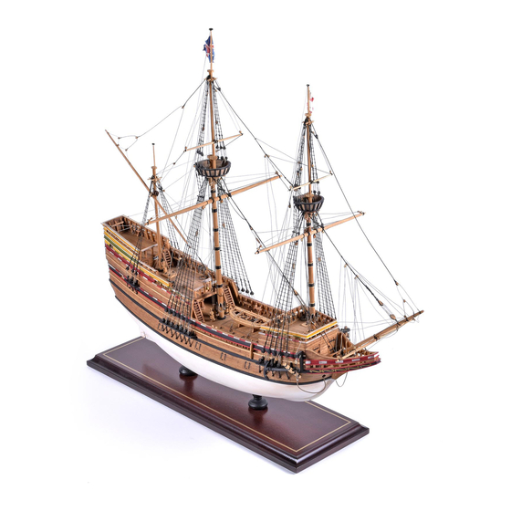
Model Shipways Kit No. MS 2020
Scale: 5/32" = 1 ft.
Overall Length: 22"
Height: 17"
Instructions and model prototype
prepared by Chuck Passaro
Manufactured by Model Shipways, Inc - Hollywood Florida
Sold by Model Expo, a division of Model Shipways, Inc. - www.modelexpo-online.com
INSTRUCTION MANUAL
Modeling The
MAYFLOWER
1620
Advertisement
Table of Contents

Related Manuals for Model Shipways Mayflower 1620


Summary of Contents for Model Shipways Mayflower 1620
- Page 1 Model Shipways Kit No. MS 2020 Scale: 5/32" = 1 ft. Overall Length: 22" Height: 17" Instructions and model prototype prepared by Chuck Passaro Manufactured by Model Shipways, Inc - Hollywood Florida Sold by Model Expo, a division of Model Shipways, Inc. - www.modelexpo-online.com...
- Page 3 Bearding line Rabbet Strip Rabbet Strip The two photos above show the rabbet strip glued to the bottom of the bulkhead former. The bulkhead former is tapered from the bearding line to the rabbet strip. ness of the bulkhead former gradually to in their respective slots on the bulkhead GETTING STARTED former.
- Page 4 which show the bulkheads and fillers glued into place on the prototype. Please Mizzen mast filler note that two fore mast fillers are supplied for the port side of the bulkhead former. Main mast filler They are both notched out to receive an eye bolt in the next step.
- Page 5 Dummy cannon support strip is positioned Gun Port Framing… two filler pieces. See the photo showing the eye bolt in position. It has been painted white so that it will show up in the photo. Take note of its orientation as the eyebolt should face forward as This Mayflower model is designed so the four gun ports on each shown.
- Page 6 False decks are in position and the hull is faired. The bulkhead edges are beveled more severely at the bow and stern Fairing the hull in preparation Also check it at mid-hull level and at the deck levels. See the photos provided showing the beveled bulkheads at the bow and for planking…...
- Page 7 The bulwark template is temporarily pinned to the hull and the bottom edge is traced onto the bulkheads. The top edge of the first plank will line up with these reference marks. Planking the hull… ond layer of planking you must cut the opening in the counter for the tiller.
- Page 8 Note the space above the initial plank at the bow. This will be planked later in the project This first jig will help you pre- bend planks around the severe curve at the bow. Several planks can be bent at one time in this simple jig.
- Page 9 Stop #2 Spiled plank Stop #1 Spiling guide This second jig helps you PRE-SPILE planks edge-wise. The curved planks will reduce the need to edge-bend the planks at the same time you are trying to glue them into position. The planks will lay flat across the bulkhead edges. The lower edge of the planks will not lift up off of the bulkheads.
- Page 10 Stealer cut to 1/2 its width and allowed to gradually taper to its full 1/8” width as it runs off the stern. The next plank is notched out to fit around the stealer. Start by making a 1/16” long cut across the width of the plank where it will butt into the end of the stealer.
- Page 11 Planking completed on the port side Planking the Decks... Hatches framed with 1/16” x 1/16” wood strips It is much easier to plank the decks now before the bulwarks are attached to the hull. Beakhead is All of the decks should be planked except not planked for the “half deck”...
- Page 12 Main hatches created first before planking. Use the grating strips provided and frame with 1/16” x 1/8” wood strips Capstan base eye bolts and rings provided with the kit. Paint them black before Planking and detailing the bulkheads… gluing them into pre-drilled holes along the hatch. There are five bulkheads that need to be planked and detailed.
- Page 13 Be sure to bend each plank so it follows the camber created by head. Test it first to see if an equal amount of the frame shows the bottom edge of the bulkhead. The hinges for the door are around the window on all four sides. You can make adjustments made using card stock that is painted black.
- Page 14 Forward Cubbridge Head Stern Transom bulkhead in position planked inboard only Poop Bulkhead Great Cabin Bulkhead The last bulkhead to address in this step is the STERN TRAN- continuous length across the templates. The two windows (port SOM. This bulkhead has no details and is pretty straight for- and starboard) can be completed using the same techniques ward.
- Page 15 Line up the bulwark template with the Cubbridge head bulkhead when gluing it on the hull. Planked inboard with 1/8” x 1/32” planks. Note the windows glued to the inboard side of bulwarks. this before you glue it into position. There are two doors shown 1/32”...
- Page 16 Completed stern with 1/8” x 1/32” four laser cut knees in planks on place between the the top windows. Planks were section also stained and treenailed. 1/8” x 1/16” thick planks on the middle section. Plank around the windows. will run right over these knees and be sanded to match their pro- file.
- Page 17 Pre-planking above the open 1/16” x 3/32” strips for bulwark areas of the bulwarks stanchions. Make them longer than you will actually need and then trim them after the pre-planking is completed. 1/16” x 1/16” 1/16” x 1/8” All open areas of the bulwarks are 1/8”...
- Page 18 The first plank placed on the hull represents the run for the upper wales. The top edge of this plank follows the bottom edge of the Bulwark template. Work your way upward from here to complete step one. this step was completed on the prototype. Notch your planks Final Layer of Planking…...
- Page 19 Step 2 is completed. The wales and trim have been glued into position. The hull has been stained and painted. which will represent the lower wales. This Remember that the upper wales are placed will be left natural and stained to match was a thicker plank as mentioned earlier over the initial plank from step one and the the underlying hull planking.
- Page 20 Port Lid Details... The stern port lids can be detailed the same way you constructed the doors for the bulkheads. Simply use some card stock for the STEP TWO: Glue two strips of 1/8” x 1/32” strips together edge- hinge straps and add a tiny length of 28 gauge wire to simulate wise to create the inboard layer of each lid.
- Page 21 Step 1 Color Scheme… Stem Knee Paint the bottom of the hull tallow - or Hole for eggshell. You might consider muting the stay collar painted areas of your model. They may appear too bright and “new”. A thin wash of watered down brown acrylic paint was used on the prototype.
- Page 22 timbers. Finally the outside of these Step 4 Support knee frames were planked over to provide pro- tection from any storms and rough weath- er. The entire beakhead is quite structural- Planking strip ly sound when completed. For our little model this construction process will be simplified.
- Page 23 The two photos above show you how to construct a capstan from the wood sup- plied in this kit. The first photograph shows a wooden dowel (3/16” diameter) cut to length. The bottom portion of the dowel (capstan drum) was filed to a six- sided shape.
- Page 24 provided to document the entire process. Photo #3 Follow the steps outlined below and examine the plans carefully for details. Step 1 – Use a scrap piece of planking as a straight edge. You can see how it was used in Photo #1. It was placed on deck against the aft side of the bulwark stan- chions shown.
- Page 25 bulk head templates. These were made Photo #8 using the plans as a guide to shape them. Trace the design on a 1/32” thick bass wood sheet and cut them free with a sharp blade. Glue them into position. Two addi- tions strips of 1/32”...
- Page 26 glued onto the rudder at a right angle to the inside edge of the rudder. This angle is clearly shown on the plans. Once in position, slide the gudgeons behind the the pins as shown in photo 1B. You can apply Tiller a drop of glue if needed to keep them in place.
- Page 27 depending on your skill level, you may Poop Deck want to replace them with some that are scratch-built. The kevels would have been Pin Rail made of wood and as such should be painted to look like wood. Examine the plans for their exact locations and glue Kevel them to the bulwark stanchions.
- Page 28 colors the groove with pencil which fur- Belfry without ther enhances the appearance of an iron roof sheave. Do this on both sides of the knight. Glue an eye bolt on one side just below the three sheaves and a kit-supplied cleat on the other.
- Page 29 so there is a photo on the previous page Upper Deck that shows a completed pump. That same photo also shows the four pieces needed to construct them. Step 1. – Create the main cylinder for the log pump. The cylinder is made using a 3/16”...
- Page 30 Chesstree Cathead Channels Channels – Examine the plans carefully for the shape and loca- Paint the channels black. Two eye bolts are glued into pre-drilled tions of the channels. You will notice that the outside edge of holes on top of the channels. Only the fore and main channels each channel is shown with a 1/16”...
- Page 31 The Ships Boat… Lifts are glued together, align tabs. The Mayflower carried a small boat. It would be a good idea to build it before you start the masting and rigging. Rather than supply a Britannia casting for the boat, seven lifts are laser cut for a bread-and-butter hull.
- Page 32 this boat are “clinker” style. This means that each plank overlaps the edge of the plank below it. Frames were added This is quite a challenge to do on such a small hull but well worth the effort. Should you decide not to place 3 or 4 clinker style planks (1/64”...
- Page 33 Tenon Three chocks/stops for gommoning Completed Bowsprit One cleat on the starboard side only one chock for stay collar on underside Typical Gammoning on a model Gammoning might be a good idea to practice on some scrap pieces of wood Masting and Rigging first.
- Page 34 Fore Mast Tenons Hounds/cheeks Four cleats Wooldings Main Mast Chock (main only) acter to your model and are historically Wood accurate for the time period. They are also Mast not difficult to create. Hoops Start by creating the wooden hoops. Mark their locations as shown on the plans.
- Page 35 outlined below to complete them. Make a photocopy of the lenge however, the tops can be modified to more closely resemble tops from the plans. In photo #2 you can see how they were those shown on the plans. The plans show a more accurate depic- used to mark the squared opening on the bottom of each top.
- Page 36 ream the eye with a pointed dowel. This Square Main top mast sheave hole helps to form the eye while the glue sets, quickly forming its shape. Push the two loose ends through the hole in the top as shown on the left side of photo #6. The Square Tenon seizing on the eye should be large enough so it doesn’t pull through the hole in the...
- Page 37 Stepped fore mast Main Stay Collar ble, the rigging will be presented in the Mizzen Stay Collar – Rigged similar to order used to rig the prototype. Stepping the Masts… the fore stay collar except a 3-hole (5mm) deadeye is used. (.021 Blk) Once again Main Stay Collar –...
- Page 38 step. You will need six of these for the mizzen shrouds. Step 3 - Slide a length of chain (about ¾” long) into position. Step 4 – Round deadeyes are supplied but can be reshaped as mentioned earlier. Use the smaller 3mm deadeyes provided. Bend the ends of the wire around the top of the deadeye as shown.
- Page 39 where the chain should be pinned. Make sure the shroud is held tightly so the cor- rect angle is easily established. Use the brass nails supplied to pin the chains to the sides of the hull (pre-dill all of the holes first). Cut the chains to length and pin them to the hull with super glue.
- Page 40 The stay (.028 Blk) is secured around the mizzen masthead on top of Main mast tackles the shrouds you just completed. Seize an eye on the end of the stay. (port and starboard) The other end of the stay is run through the eye and synched up like a noose around the mast head.
- Page 41 Main stay and main mast shrouds Main stay collar Main stay mouse Main Stay... Fore Shrouds... When the main shrouds are finished you can rig the main stay. It These shrouds are rigged like the mizzen and main shrouds. is secured to the main stay collar with a lanyard and deadeye. It There are five per side and the 5mm deadeyes are used.
- Page 42 Futtock Shrouds… The futtock shrouds can be rigged next. Each shroud (.021 black) has a hook seized onto one end. This hook is secured to the eyes located beneath the rim of the top. These are the eyes you formed for each of the three deadeyes on both sides of the top.
- Page 43 mouse Main topmast stay collar Fore topmast tackles Main topmast stay (.028 blk) Fore topmast stay (.028 blk) 1/8” single block Pendant (.021 tan) Belaying the fore topmast runner 3/32” single blocks Rigging the fore Runner (.018 tan) topmast stay...
- Page 44 Ratlines... Rig the ratlines on all of the shrouds as shown in the drawing to the left. Check the plans for the appropriate distance between them (approx. 3/16”)(.008 BLK). Garnet Tackle... The Garnet tackle consists of a pendant, a runner and the falls. The pendant (.021 BLK) is hitched around the main masthead above the shrouds and taken through the main stay loop.
- Page 45 positioned just below the tops and can be seen on the standing and seize a fiddle block to its end as shown on the plans and in rigging plan. the photo provided on the previous page. Note that the fiddle block can be made from scratch or you can substitute a 1/8”...
- Page 46 The tie (.021 BLK) is used to raise and lower the yard to the The lifts are the last lines rigged on the lateen yard. They consist deck. Secure the tie around the yard as shown on the rigging of the pendant (.028 BLK), the runner (.021 Tan), the falls (.018 plan.
- Page 47 Main yard braces Topsail lifts Main yard lifts Topsail sheets The main yard was raised and lowered on the opposite side of the mast (hounds). The model is going to be finished without using ties similar to the lateen yard. This From here the loose end of the tie is sails.
- Page 48 The braces (.018 Tan) for the main yard the single blocks of the brace pendants. Secure the tie (.028 BLK) and ramshead are seized to an eyebolt on the outside of The loose end is taken back through a sin- block to the fore yard as you did with the the hull.
- Page 49 to yard as called for on the plans. The yard can then be secured to the bowsprit with a simple sling. Create the same sim- ple sling that you made for the topsail Rigging the yards. The spritsail yard should also be fore yard and placed in the lowered position as it has no fore topmast...
- Page 50 Lifts Halyard Garne ts Braces Spritsail Yard Rigging can be glued into position as shown in the the model accidentally. look like wood. The Anchor stock has photo below. To help secure this yard on several iron straps which should be painted the model a short length of wire can be The Anchors...
- Page 51 Anchor rigged on the model late the iron bands. The wood stocks can forecastle deck. Finish it off with a rope be treenailed as shown in the photo above coil. for even greater detail. Create a ring from black wire and use it for the anchor ring. The last step in building your model of the Wrap the wire around a drill bit that is the Mayflower is to rig the flags.
- Page 52 The Mayflower sailed for the new world on it The plans for this Mayflower model are based on historical voyage in September 1620. The the latest research available and the work by Pilgrims came to America seeking religious free- noted Naval Architect William A. Baker. Mr. dom during the reign of King James I.
Need help?
Do you have a question about the Mayflower 1620 and is the answer not in the manual?
Questions and answers