Table of Contents
Advertisement
Quick Links
Advertisement
Table of Contents

Subscribe to Our Youtube Channel
Related Manuals for Model Shipways Charles W.Morgan


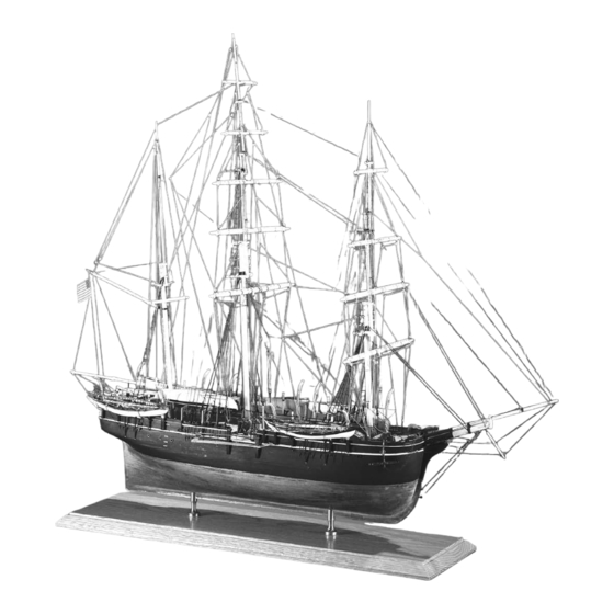
Summary of Contents for Model Shipways Charles W.Morgan
- Page 1 INSTRUCTION MANUAL NEW BEDFORD WHALING BARK 1841 Technical Characteristics SCALE: 3/16" = 1'0" (1:64) Overall length: 30-3/4 " (781 MM) Overall height (including baseboard): 27-7/8" (708 MM) Overall width (main yard): 10-1/8" (257 MM) . 2140 ODEL HIPWAYS...
-
Page 2: Brief History
HIST HIST Charles W. Morgan was built in 1841 at the Hillman Brothers’ Shipyard on the Acushnet River in New Bedford, Massachusetts. She cost $52,000 and was registered at 351 tons, 106’ 6” x 27’2-1/2” x 13’ 7-1/2”. Her primary owner was Charles Waln Morgan, a Philadelphia-born Quaker. The first of Morgan’s 37 successful worldwide expeditions began on September 6, 1841. -
Page 3: Table Of Contents
BLE OF CONTENTS BLE OF CONTENTS Brief History Open Chocks, Starboard Rail Chock, Introduction and Credits and Cleats Eyebolts Before You Begin Tools Needed to Start Construction Rudder and Steering Wheel How to Work With Plans & Parts Cutting Stage Whaleboat Davits, Bearers Painting and Staining (Lashing Posts), Cranes and Slides... -
Page 4: Introduction And Credits
By Ben Lankford Model by Bob Bruetsch Model Shipways’ Charles W. Morgan kit was developed in 1994-’97. Plans are based on drawings and other information provided by Mystic Seaport, and from pho- tographs taken by the author in 1994. The Model Shipways plans and instructions were reviewed by Mystic Seaport for accuracy. -
Page 5: Before You Begin
Before You Begin Tools Needed to Start Construction Charles W. Morgan is an interesting The following items are recommended for building the model. ship and makes a splendid model. Those who have modeled before may have their favorites. Assembling the plank-on-bulkhead A. -
Page 6: How To Work With Plans & Parts
“tick” strip (piece of paper such as an adding machine roll). Lay the Note: Model Shipways occasionally sub- Cut brass sheets and strips with a small paper strip over the plan, carefully mark stitutes lime (Tilia vulgaris), a European pair of tin snips or heavy scissors. -
Page 7: Painting And Staining
Painting and Staining the Model for backing. (Avoid softwoods, as these Beginning this manual with directions Stains and Finishes flare the exit hole.) To prevent the bit on applying finishes may seem strange. from wandering, mark the spot with a Not so! Much time and effort can be Tone wood with Floquil or Minwax small center punch. -
Page 8: Stage 1: Framing The Plank-On-Bulkhead Hull
Fig. 1-1 Center Keel Assembly STAGE 1 Wax paper or plastic wrap Framing the Plank-on-Bulkhead Hull Weight 1. Bending Wood Glue joint let dry 24 hrs. Building a P-O-B hull requires bending some wood without distorting its Building board 3/4" particle desired position (doing so stresses glue Use straight edge to board recommended... -
Page 9: Center Keel Assembly
2. Center Keel Assembly Fig. 1-5 Gluing Bulkheads to Center Keel The first step in constructing the hull is to assemble the two laser-cut center keel Pin or tape pieces. First, use a sharp pencil and mark the bulkhead locations below the slots and reference line (used to locate Bulkheads A through O). -
Page 10: Installing The Bulkheads
5. Installing the Bulkheads Fig. 1-8 Checking Hull Fairness with a Batten Compare the laser-cut bulkheads with the pattern plan, determine which is which, Bulkhead and label them A through O. Test each to make sure it will slide into the center keel slots. -
Page 11: Installing The Transom Framing
6. Installing the Transom Fig. 1-11 Using Batten to Align Bulwark Stanchions Framing Follow the plans when carving the Clamp temporary batten counter block. Its bottom reflects the counter curve, while its forward side matches Bulkhead O. The aft side indi- cates the slope and curvature of the tran- som. -
Page 12: Stage 2: Planking The Hull
STAGE 2 Planking the Hull Before starting, it’s a good idea to know some common shipbuilding terms that apply to the planking process. Plank: A single length of wood used to plank a hull or deck. A strake is a con- tinuous line of planks from wherever it begins to where it ends. -
Page 13: Spiling
4. Spiling Fig. 2-1 Planking Shown Using Stealer Inserts Edge-bending planks on real ships is done on a limited basis. Wood is rigid, so many planks must be cut to shape. Spiling (Figure 2-3) is simply a matter of transferring curves to a straight plank, then sawing them out. - Page 14 Planking will require tapering fore and Fig. 2-4 Transom-Hull Plank Intersection Options aft from the top of the wale down to the keel. Consequently, the hull below Joint mitered, or as option taper the wale is divided into Belts A only the hull plank when installed through D.
- Page 15 Side Planking Above the Wale: Planking is Fig. 2-7 Installing Deck Hatch Coaming Supports 3/64” thick from the top of the wale to the planksheer. From planksheer to main rail, it is 1/32” thick. These planks Coaming Bulkhead are fairly uniform in width from bow to stern and can be easily fitted.
-
Page 16: Planking Inboard (Ceiling Planks)
7. Planking Inboard Deck Planks: Main deck planks are Anchor Deck: Before planking the 1/16” thick. Anchor deck planks are anchor deck, paint the areas under- (Ceiling Planks) 1/32” thick. Planking runs parallel to neath it, then add the bowsprit bitts the centerline. -
Page 17: Stage 3: Completing The Basic Hull Structure
Fig. 3-1 Installing Copper Sheathing STAGE 3 Cap plates fitted over keel, Keel stem, sternpost and rudder Completing the Basic Hull Structure 1. Correcting and Sanding Sternpost Once all the planks are installed, exam- ine the hull. Rub wood glue in cracks or add filler. -
Page 18: Stage 4: Mounting The Hull
STAGE 4 Mounting the Hull Before proceeding farther, mount the hull to prevent damaging fittings when han- dling the model. Proper mounting is important, because future alignments will require a true waterline. This kit contains two brass pedestals and a baseboard for displaying the model. - Page 19 Fig. 5-1 Building Deck Structures 1/32" thick vertical or horizontal planking Option-use solid or scribed sheet 3/32"-1/8" sq. corner Overhead planking or mid-house post Plank backing strip Moldings Beam and post Dowel for space about 1" on alignment Coaming centers A.
-
Page 20: Hatches And Gratings
4. Hatches and Gratings Fig. 5-3 Assembly of Grating Strips If the coamings are installed, make the hatch covers or gratings. Precedence exists for displaying the model with hatches covered. Gratings on the hatch, and companion doors are to provide ventilation at Mystic Seaport. -
Page 21: Main Fife Rail And Bilge Pumps
9. Main Fife Rail and Fig. 5-6 Building Ladders Bilge Pumps Stile holder Make the bitts and fife rail from wood. Stanchions are Britannia. Britannia bilge Tread holder Snug fit pumps secure to the rail, so drill holes (angle slots) in the deck to accept them. -
Page 22: Deck Bitts, Fluke Pipe And Belly Chain Chock
13. Deck Bitts, Fluke Pipe, and Belly Chain Chock A whaler has three important bitts and corresponding chocks on its starboard side. Forward is the fluke chain bitt to which a chain is attached. It feeds through the fluke pipe in the hull. The chain is tied to the whale’s tail when cutting-in. -
Page 23: Rudder And Steering Wheel
Eyebolts are simply wire bent into a loop. To close the loop, touch with a lit- Fig. 5-10 Deck Bitts Chamfer tle solder or epoxy. Figure 5-11 shows an easy way to produce scale eyebolts. Brass pin 18. Rudder and Steering Wheel Fluke chain, belly, and head bitts all similar... -
Page 24: Ship's Name
the exterior hull to its correct profile. Be Fig. 5-14 Whaleboat Davit Stowage careful; the hull is becoming thin. Make templates from the body lines to fine tune the hull’s shape. Add the keel and rudder and the basic hull is done. Stay brass Davit Carving a small boat hull is difficult. -
Page 25: Miscellaneous Boxes
Fig. 5-16 Homemade Double-Ended Caliper The stern eagle and billethead are Bri- tannia. Paint on the stars at the stern. Gap is hull thickness Pin or bolt at center 25. Sea Ladder and Portlights "B" "A" Morgan has sea ladders (wooden steps) on either side of the hull. -
Page 26: Stage 6: Mast And Spar Construction
Fig. 6-1 Shaping & Tapering the Masts and Spars STAGE 6 Straight line - No! After squaring mast heads to their proper width, cut the tenon or tongue at the top (Figure 6-2). Bottom of mast, max. dia. of On most ships, the heel of the topmasts gaff / boom, or Cl. -
Page 27: Building And Installing The Bowsprit And Jibboom
eyebolt in place. Pin hole for securing Pin to hold Fig. 6-4 Making Mast Iron Bands parts while band to spar Britannia spider bands may need their soldering Solder - this can To form wrap around holes filed before they will slip on the represent the bolted drill rod or dowel masts. -
Page 28: Sailmaking Information
as possible. They will be installed later. Fig. 6-7 Making a Wooden Jackstay Note: The maximum diameter of the gaff and boom is not at the center, but Pin to spar about one-third out from the forward end. This is not clearly seen on the Wood strip plans. - Page 29 STAGE 7 Lanyards are lines used to tighten shrouds, stays, or other lines. On mod- ern ships, metal turnbuckles have replaced deadeyes. A heart or bullseye is similar to a deadeye, except it has one large hole. They are used for more per- manent installations.
-
Page 30: Rigging Options
boom. When not in use, sails are furled Fig. 7-3 Stropping Model Blocks (bundled on the yard, boom, or mast). Clew lines pull up the corners of a square sail, leechlines pull up the sides, Wire strop and buntlines pull up the belly for furling the sail. -
Page 31: Treating The Lines
or cotton lines. Stropping 3/16” scale blocks is diffi- cult. Some alternatives are shown in Figure 7-3. 4. Treating the Lines Worming, Parceling, and Serving: Lines on Stretching the Sails: This step assures the ships were wormed, parceled, and 8. Sailmaking sail’s proper shape, since sewing may served wherever chafing might occur. -
Page 32: Rigging The Model Without Sails
sails may require being reduced by one- third. Test first to see how much materi- al is required for a neat, tight furl. Even furled sails need some seams and hems, as these details are visible. 9. Rigging the Model Without Sails Even though sails are omitted, include most of the lines attached to them;... -
Page 33: Stage 8: Standing Rigging
Fig. 8-2 Deadeye Spacing & Seizing Details STAGE 8 The rigging plan shows the proper sequence for installing the shrouds. To set up the shrouds, make a temporary brass 1. Pull tight wire fixture to space the deadeyes as seiz- ing progresses (Figure 8-2). -
Page 34: Fore And Aft Stays
Topmast, topgallant, and royal back- Fig. 8-4 Ratlines stays are similar to shrouds, except no ratlines connect them. Install them after the shrouds are up. Note: The royal backstays use bullseyes rather then deadeyes and set to an eyebolt instead Thread with of a chainplate. -
Page 35: Footropes, Furling Stops And Fixed Lifts
smallest chain provided. 6. Footropes, Furling Stops and Fixed Lifts As noted earlier footropes, and even the ends of fixed lifts, are easier to install with the spars in hand. Like the ratlines, footropes may require some work before they hang naturally. Add the footropes on the jibboom. -
Page 36: Spanker And Gaff Topsail
Fig. 9-1 Jib Rigging Without Sail Note: Some belaying points for the lower staysail sheets were not identi- fied on Mystic’s drawings. Consequently, Model Shipways’ plans Halliard reflect an educated guess. 3. Spanker and Gaff Topsail Downhaul Set up the gaff and boom topping lifts, then hook the gaff and boom to the mast eyebolts. -
Page 37: Fore And Main Topgallent Yards
Fig 9-3 Lower Course Rig Without Sail The lower topsail yard is fixed. Secure it to the truss, then add the chain sling. Set the upper topsail to the tub parrel. Bunt and leech lines knotted off at thimbles, or omit The plans show these yards rigged with furled sails and with no sails. -
Page 38: Miscellaneous Rigging
Fig 9-6 Brace Runs Braces can be installed taut, or allowed to droop a bit. If not taut, beeswax them thoroughly and shape with your fingers until they hang in a realistic curve. Some brace runs are shown in Figure 9-6. Main upper topsail brace Main lower Thimbles... -
Page 39: Bibliography
8. To Build a Whaleboat, by Erik A.R.Ronnberg, Jr., Model Shipways This is a Model Shipways publication which accompanies the Model Shipways whale- boat kit. Wonderful for a close-up view of the small whaleboats carried by the whalers. - Page 40 NATURE COAST HOBBY SHOP Authorized dealer for Model Shipways http://www.naturecoast.com/hobby Toll Free 1-800-714-9478...
Need help?
Do you have a question about the Charles W.Morgan and is the answer not in the manual?
Questions and answers