Table of Contents
Advertisement
Quick Links
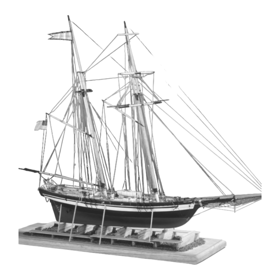
The Baltimore Clipper
P R I D E
O F
B A L T I M O R E
II
Early History
A type of sailing vessel known as the Baltimore
Clipper first appeared during the American
Revolution. Because the ship was so fast,
it's hull design became a favorite and was
patterned after by privateers, slavers, and
others desiring rapid transportation on
the sea. The Baltimore Clipper was
fully developed and most success-
ful during the period from 1805 to
1815 and is generally accepted
as the precursor to the Clipper
ship era of the 1850's.
(continued on page 3)
Technical Characteristics
Scale: 3/16" = 1' 0" (1: 64)
Length: 32"
Width: 5-1/4"
Height: 22-1/4"
Model Shipways
Kit No. MS2120
Advertisement
Table of Contents

Related Manuals for Model Shipways MS2120


Summary of Contents for Model Shipways MS2120
- Page 1 1815 and is generally accepted as the precursor to the Clipper ship era of the 1850’s. (continued on page 3) Technical Characteristics Scale: 3/16” = 1’ 0” (1: 64) Length: 32” Width: 5-1/4” Height: 22-1/4” Model Shipways Kit No. MS2120...
-
Page 4: Introduction/Credits
Built-up Model by Bob Bruetsch, 1994 Detail photos of actual ship by Bob Bruetsch, 1994 The Model Shipways plans for Pride of Baltimore II were prepared in 1993 and 1994. They were developed from the original design drawings for the ship by Naval Architect Thomas C. - Page 5 (Continued from cover) It was as a privateer during the War of 1812 that the Baltimore In late 1976, the ship was official- Clipper became most famous. With sleek lines and few guns, the ly named the Pride of Baltimore, Baltimore Clippers were light and exceptionally fast.
-
Page 6: Table Of Contents
CONSTRUCTION STAGES AND TABLE OF CONTENTS Brief History Cover, pg 3 23. Props & Struts Pg 27 Introduction/Credits Pg 4 24. Rudder Pg 27 Before You Begin Pg 7 25. Swivel Guns Pg 27 What You’ll Need to Start Construction Pg 7 26. -
Page 7: Before You Begin
BEFORE YOU BEGIN WHAT YOU’LL NEED TO START CONSTRUCTION The Pride of Baltimore II is a very beautiful schooner and makes a The following tools and supplies are recommended for the con- splendid model. The plank-on-bulkhead hull construction with struction process. Modelers who have built before may have their laser-cut parts offers a unique building experience. -
Page 8: How To Work With The Plans & Parts
A complete set of hull lines is not shown on the plans because they HOW TO WORK WITH THE PLANS & PARTS are not needed for this particular model. With the plank-on-bulk- head construction, the laser-cut bulkheads and center keel define the hull form. -
Page 9: Painting & Staining The Model
Drilling holes in brass can be accomplished using small drills If you use a paint other than Model Shipways, match the Model and a pin vise, which is a slow process. A Dremel Moto-Tool Shipways color referenced on the plans with the paint you select, mounted on a Dremel drill press is ideal. -
Page 10: Stage A: Framing The Plank-On-Bulkhead Hull
STAGE A FRAMING THE PLANK-ON-BULKHEAD HULL 1. Bending Wood Building a P-O-B hull requires some wood bending and twisting, and the wood must remain in the desired position so as not to put too much stress on glue joints and fasteners. The term “steam-bent” will be used throughout the text whenever such a process is necessary. -
Page 11: Installing The Keel/Stem & Sternpost
4. Installing the Keel/Stem & Sternpost FIG. 5 – Squaring the Bulkheads The ship has no real point of change between the keel and stem, so we will call it a keel/stem. The laser-cut Bulkheads keel/stem, and sternpost can now be added. Taper the keel/stem according to the plans before gluing in place or do it later. -
Page 12: Installing The Transom Framing
Next, check the fairness of the hull form and sand in the slight bevels that were not pre-cut. To do this, use FIG. 8 – Fairing the Hull Form a stiff basswood batten about 3/32” thick and lay it across the bulkhead edges and deck in various loca- tions (see figure 8). -
Page 13: Installing The Hawse Timbers
Glue the two-piece planksheer together, then glue it to the top of the bulkheads, port and starboard. The planksheer should extend beyond the edge of the bulkheads by 3/32”. After the hull planking is added, the planksheer will protrude out from the planks by 1/32”. -
Page 14: Stage B: Planking The Plank-On-Bulkhead Hull
in smooth curves. Each belt is designed so the planks STAGE B lay against the hull without having to excessively edge bend them. They sweep up at the ends like the deck sheer. Within each belt, the planks are usually PLANKING THE PLANK-ON-BULKHEAD HULL spaced evenly, tapered, and fitted as required. -
Page 15: Spiling
4. Spiling Edge-bending planks on a real ship is done, but it is limited. The wood is very stiff, so many planks must be cut to shape. Spiling is the term used for laying out the cuts (see figure 16). It’s simply a matter of trans- ferring curves to a straight plank, then sawing the plank to shape. - Page 16 FIG. 17 – Batten Layout Main rail Planksheer Look for smooth flow Bottom wale of battens “A” “B” “C” “D” Battens lose them. You could now remove the temporary bat- tens or leave them in place until they need to be FIG.
- Page 17 Laying the Planks in Belt A: Each belt of planking Laying the Planks in Belt B: This belt is very similar to should be done separately. Consequently, you can Belt A. It has six plank strakes about the same width start with any belt.
-
Page 18: Planking The Transom & Counter
7. Planking the Transom & Counter For the model, the side hull planks can be extended past the counter (bottom curved portion of the stern overhang), and the 1/16”-thick counter planks butted into the hull planks or vice versa. On the real ship, however, the counter plank meets the hull plank in a miter joint. -
Page 19: Planking The Deck
The top 3/64” plank should continue across the gun- ports. Apply a 1/32”-square vertical strip of wood on each side of the gunport, simply to cover the end grain of the bulwark plank (you could omit this on the model). Next, fit a fashion piece on each side of the transom as shown (see figure 26). -
Page 20: Stage C: Completing The Basic Hull Structure
STAGE C COMPLETING THE BASIC HULL STRUCTURE 1. Correcting & Sanding After all the planks are installed, look over the entire hull. If you find seams with starved glue joints, rub some wood glue in the cracks and, if necessary, add some wood filler. -
Page 21: Stage D: Mounting The Hull
STAGE D STAGE E MOUNTING THE HULL ADDING THE HULL DETAILS 1. Locating Deck Fittings & Structures Before continuing with additional work it is best to mount the hull. Doing this step will help prevent If you included the coamings when planking the details from becoming damaged while you handle deck, you at least have those structures located. -
Page 22: Ventilator Boxes & Mushroom Vents
Some details of the various components on the tops of the trunks are shown (see figure 32). Companion- way slide rails and some of the other components must be 1/64” thick. Sand down the 1/32” stock supplied. You could also use 1/64” aircraft ply- wood, but as mentioned earlier, it will not stain the same as basswood, so you probably would get a mis- match in color. - Page 23 The steering wheel on the actual Pride of Baltimore II. The binnacle as it exists today. Pride of Baltimore II cabin trunks & hatches.
-
Page 24: Deck Lockers
8. Deck Lockers There are five deck lockers which are simple boxes. One has a set of doors. It contains propane tanks. Like the vent boxes, these boxes do not have built-in coamings. All the lockers are complete boxes (have their own bottoms), but are permanently secured to the deck with bolts and in the locations shown on the plans. -
Page 25: Pin Rails
12. Pin Rails The pin rails at the shrouds are attached directly below the main rail to the bulwark stanchions (see figure 40). The real ship rails hold 19”-long conven- tional belaying pins. Brass belaying pins are provid- ed in the kit. The pin rail at the bow is actually a tri- angular platform. -
Page 26: Steps
17. Steps The small steps port and starboard shown on the plans are used for stepping up to the gangway when in port. Make these using 1/32” basswood sanded to 1/64”. 18. Lifelines The kit provides brass wire for making the lifeline stanchions for inserting in the main rail (see figure 44). -
Page 27: Props & Struts
23. Props & Struts The props have been supplied in the kit as Britannia castings (see figure 46). Paint them to look like brass. The struts should be made from brass strip and tub- ing. Brass rod is provided for the shaft. The shaft should be steel so it can be painted silver or a dull black. -
Page 28: Ship's Name
30. Ship’s Name The PRIDE OF BALTIMORE II name should be let- tered on the stern and bow as shown on the plans. Also, the name CHASSEUR must be applied to the stern of the ship’s boat. The best way to add these details is to use dry transfer letters. -
Page 29: Stage F: Mast & Spar Construction
STAGE F MAST & SPAR CONSTRUCTION At this point, your model should have a considerable amount of stuff on board. Take another look, correct any mistakes and touch up paint blemishes. Go over the plans again. Did you miss anything? The Pride of Baltimore II has a lot of detail on the deck. - Page 30 gon is equal to the diameter of the round part of the mast above. This means that the distance across the corners of the octagon is larger than the diameter of the round part of the mast. The dowel provided in the kit is 5/16”...
-
Page 31: Building & Installing The Bowsprit, Jibboom, Dolphin Striker & Jibboom Spreaders
Cleats: Finally, add the cleats around the fore mast as shown on the plans. The cleats are supplied as Bri- tannia fittings but you can make them from wood if desired. In any case, drill a hole through the cleat and insert a pin for securing the cleat to the mast. -
Page 32: Building The Main Boom & Gaffs
There are a number of cleats, yokes, and other fittings that need to be added to the shaped spar. Plan sheet 4 shows all of the detail. You will discover the use of the various cleats when you get to plan sheet 5 and start the rigging process. -
Page 33: Stage G: General Rigging & Sailmaking Information
the outer halliard is the peak halliard and at the gaff jaws STAGE G is a throat halliard, named for the part of the sail it oper- ates. Downhauls, outhauls and inhauls haul a sail along a boom, or up and down on a stay. Sheets hold the lower GENERAL RIGGING corners of a sail or boom. -
Page 34: Using The Rigging Plans
not as top heavy as the one in item A, but still has 3. Rigging Line Sizes & Colors some of the drawbacks of cutting out the detail. Actu- The rigging lines provided in the kit do not cover all ally, a topsail schooner is a better candidate for sails the sizes shown on the plans. - Page 35 Rigging lines belayed to fore mast cleats. Details at the lower main mast. Pride of Baltimore II windlass. Swivel gun at the railing.
-
Page 36: Rigging Tools
tackle before it goes to the belaying pin. In this case a detail will be referenced to show the tackle, then the belay number is referenced. On this particular ship, conventional belaying pins as we know them are used at the side pin rails at the shrouds, and in the main rail aft. -
Page 37: Rigging The Model Without Sails
piece of scrap cloth and set the tension so the thread does not make puckers in the stitch line. No actual reinforcement patches need be used. Instead, simply sew two stitch lines to represent reinforcements, such as the reef bands (see figure 70). After the stitching is completed, you may iron the sails. -
Page 38: Stage H: Standing Rigging
STAGE H STANDING RIGGING Keep your standing lines handy, sorted by sizes, and have them all nicely beeswaxed before you start. For seizings, you can use cotton, silk, or nylon sewing thread. These also should be beeswaxed beforehand. Keep your white and super glues handy for dabbing to seizings, if necessary, to hold them in place. -
Page 39: Fore & Aft Stays
4. Fore & Aft Stays The bobstays should be a double line seized togeth- er. Use bullseyes rather than deadeyes. If the kit con- Install the fore and aft stays after you have complet- tains no bullseyes, simply ream out holes in some ed the shrouds (see figure 76 for some detail at the deadeyes and use them. -
Page 40: Stage I: Running Rigging
The upper block for the jib and staysail halliard jig STAGE I can remain in the same location with or without sails. Since the hauling is done on the other end, the jig blocks will not move when sails are raised or low- RUNNING RIGGING ered. -
Page 41: Main Gaff Staysail
5. Main Gaff Staysail Add all the necessary lines to the sail before installa- tion. Seize the sail to the mast hoops, then run all the lines to their respective belaying points. Like the head sails, there is a port and starboard sheet. One is tight, the other passes over the main gaff loosely to the other side. -
Page 42: Studding Sails
7. Studding Sails Bend the stunsail to the stunsail yard with lacing sim- ilar to the gaffs. The halliard should go through a block on the topsail yard. Notice on plan sheet 6 that the stunsail tack goes to deck at the aft cavel when in use. -
Page 43: Final Touches
board on the main shrouds. The details of this tackle and the stowage method are shown on plan sheet 6. 10. Final Touches After all the rigging is in place, recheck every line, and make sure all the seizings are sound. If necessary, add another touch of super glue to seizings. -
Page 44: Bibliography
RIGGING LINE DIAMETERS BIBLIOGRAPHY 10mm (.004") 1. The Baltimore Clipper, by Howard Irving Chapelle. 1930, Marine Research Society. Reprinted by Bonanza Books, .20mm (.008") Crown Publishing. This is a complete history of the Balti- more Clipper type. It contains many plans of contemporary schooners. - Page 47 MODELER'S LOG Date Time Notes MODEL SHIPWAYS, INC. Sold & distributed by Model Expo • Hollywood, FL 33020...
- Page 48 Model Shipways Kit No. MS2120 MODEL SHIPWAYS, INC. Sold & Distributed by Model Expo, a division of Model Shipways, Inc. 3850 N. 29th Terrace, Hollywood, FL 33020 These models can be purchased through Tallships,Inc. an authorized dealer for Model Expo.
Need help?
Do you have a question about the MS2120 and is the answer not in the manual?
Questions and answers