Advertisement
Quick Links
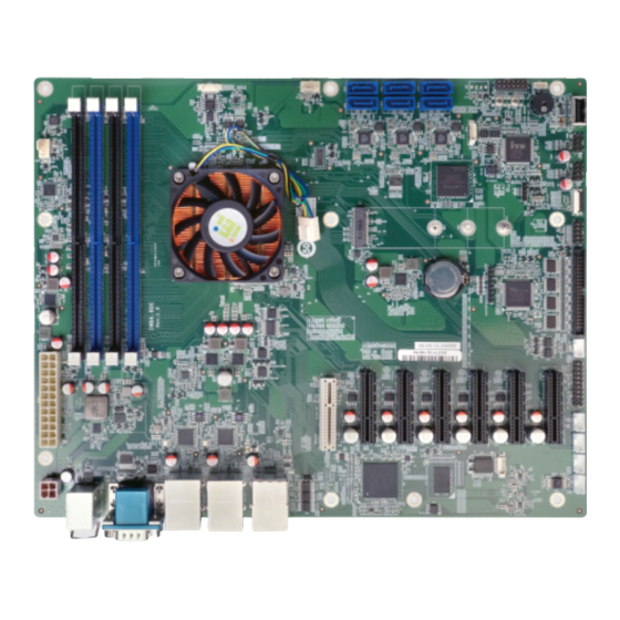
ATX motherboard supports 14nm Intel® Xeon® D1500 family, DDR4,
VGA, dual Intel® GbE/dual Intel® 10GbE, four USB 3.0,
Quick Installation Guide
Package List
IMBA-BDE package includes the following items:
1 x IMBA-BDE single board computer
1 x I/O shielding
2 x SATA cable
1 x Utility CD
1 x QIG
1 x One Key Recovery CD
©2017 Copyright by IEI Integration corp.
All manuals and user guides at all-guides.com
six SATA 6Gb/s, RoHS
IMBA-BDE
Version 1.0
Apr 28, 2017
All rights reserved.
1
Advertisement

Related Manuals for IEI Technology IMBA-BDE


Summary of Contents for IEI Technology IMBA-BDE
- Page 1 VGA, dual Intel® GbE/dual Intel® 10GbE, four USB 3.0, six SATA 6Gb/s, RoHS IMBA-BDE Quick Installation Guide Version 1.0 Apr 28, 2017 Package List IMBA-BDE package includes the following items: 1 x IMBA-BDE single board computer 1 x I/O shielding 2 x SATA cable ...
- Page 2 All manuals and user guides at all-guides.com Specifications CPU: Intel® Xeon processor D-1500 product family BIOS: AMI BIOS Memory: Four 288-pin 2133 MHz dual-channel DDR4 SDRAM unbuffered DIMMs support up to 128 GB Display Output: 1 x VGA (up to 1920x1200@60 Hz) ...
- Page 3 All manuals and user guides at all-guides.com I²C: 1 x I²C (1x4 pin) Digital I/O: 8-bit digital I/O (2x5 pin) Expansion : 1 x 10GbE LAN card slot (white PCIe x 8 slot) 1 x M.2 connector (M key, 2242~2280, SATA & PCIe x2 signal) 1 x PCIe x4 Gen 2 (PCIE2x4_1) 5 x PCIe x4 Gen 3...
-
Page 4: Ordering Information
All manuals and user guides at all-guides.com Ordering Information IMBA-BDE-1548-R10: ATX motherboard supports 14nm Intel® Xeon® D-1548, DDR4, VGA, dual Intel® GbE/dual 10GbE, four USB 3.0, six SATA 6Gb/s, RoHS IMBA-BDE-1518-R10: ATX motherboard supports 14nm Intel® Xeon® D-1518, DDR4, VGA, dual Intel®... -
Page 5: Jumpers Setting And Connectors
All manuals and user guides at all-guides.com Jumpers setting and connectors LABEL FUNCTION J_ATX_AT1 AT/ATX Mode Select Switch JP2, JP3 Clear CMOS Button CPU Fan Connector 12V_ATX1 +12V Power Connector ATX1 ATX Power Connector JDIMM1, JDIMM2, DDR4 DIMM slots JDIMM3, JDIMM4 DIO1 Digital Input / Output Connector EC Debug Port Connector... - Page 6 All manuals and user guides at all-guides.com J_ATX_AT1: AT/ATX Power Mode Setting PIN NO. DESCRIPTION Short A-B ATX Power Mode (default) Short B-C AT Power Mode JP2, JP3: Clear CMOS Setup PIN NO. DESCRIPTION Keep CMOS Setup Short 1-2 (default) (Normal Operation) Short 2-3 Clear CMOS Setup...
- Page 7 All manuals and user guides at all-guides.com LAN2_USB2: RJ45 LAN and USB 2.0 Connector LAN2: RJ45 LAN connector PIN NO. DESCRIPTION PIN NO. DESCRIPTION MD0+ MD0- MD1+ MD1- MD2+ MD2- MD3+ MD3- LINK_ACT+ LINK_ACT- 100- 1000- USB2: External USB 2.0 connectors PIN NO.
- Page 8 All manuals and user guides at all-guides.com COM1: External RS-232 serial port connector PIN NO. DESCRIPTION DATA CARRIER DETECT (DCD1) RECEIVE DATA (RXD1) TRANSMIT DATA (TXD1) DATA TERMINAL READY (DTR1) (GND1) DATA SET READY (DSR1) REQUEST TO SEND (RTS1) CLEAR TO SEND (CTS1) RING INDICATOR (RI1)
- Page 9 All manuals and user guides at all-guides.com COM2: Internal RS422/485 Connector PIN NO. DESCRIPTION PIN NO. DESCRIPTION RXD485# RXD485+ TXD485+ TXD485# COM3-6: Internal RS-232 serial port connectors Function DESCRIPTION DESCRIPTION COM3 COM4 COM5 COM6...
- Page 10 All manuals and user guides at all-guides.com SATA0~5: Serial ATA 3.0 connectors PIN NO. DESCRIPTION PIN NO. DESCRIPTION JSPI1: SPI Programming Connector For System BIOS PIN NO. DESCRIPTION PIN NO. DESCRIPTION +V3.3M_SPI_CON SPI_CS SPI_SO_SW SPI_CLK_SW SPI_SI_SW JSPI2: SPI Programming Connector For EC PIN NO.
- Page 11 All manuals and user guides at all-guides.com DIO1: Digital Input / Output Connector PIN NO. DESCRIPTION PIN NO. DESCRIPTION +V5S DOUT4 DOUT3 DOUT2 DOUT1 DIN4 DIN3 DIN2 DIN1 F_PANEL1: External Switches and Indicators Panel DESCRIPTION DESCRIPTION LED_PWR BEEP_PWR SPKR PWR_BTN PC_BEEP# SATA_LED+ RESET...
- Page 12 All manuals and user guides at all-guides.com 12V_ATX1: +12V Power Connector PIN NO. DESCRIPTION PIN NO. DESCRIPTION +12V +12V CN7: EC Debug Port Connector PIN NO. DESCRIPTION PIN NO. DESCRIPTION EC_EPP_STB# EC_EPP_AFD# EC_EPP_PD0 EC_EPP_PD1 EC_EPP_INIT# EC_EPP_PD2 EC_EPP_SLIN# EC_EPP_PD3 EC_EPP_PD4 EC_EPP_PD5 EC_EPP_BUSY EC_EPP_PD6 EC_EPP_KSI5...
- Page 13 All manuals and user guides at all-guides.com CN13: SMBus Connector PIN NO. DESCRIPTION PIN NO. DESCRIPTION SMB_DATA SMB_CLK J2: EC SMBUS Debug Connector PIN NO. DESCRIPTION PIN NO. DESCRIPTION 3.3V EC_SMB_CLK EC_SMB_DAT USB1, USB2: Internal USB 2.0 connectors PIN NO. DESCRIPTION PIN NO.
- Page 14 All manuals and user guides at all-guides.com Board Layout: Jumper and Connector Locations (Unit: mm)
Need help?
Do you have a question about the IMBA-BDE and is the answer not in the manual?
Questions and answers