Table of Contents
Advertisement
Quick Links
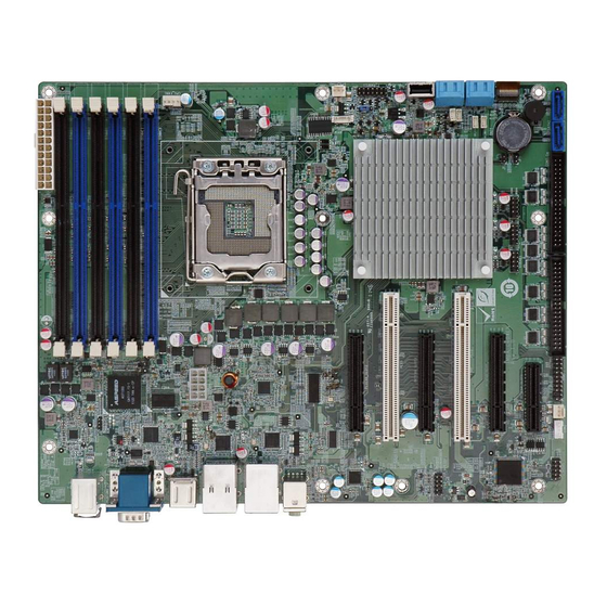
IMBA-C604EN ATX Mo th e rb o a rd
IEI Te c h n o lo g y Co rp .
MODEL:
IMBA-C604EN
ATX s e rve r b o a rd s u p p o rts 32n m LGA1356 In te l® Xe o n ®
E5-2400 s e rie s u p to 8 c o re s CP U with In te l® C604, DDR3,
VGA, P CIe Ge n 3.0, Fo u r S AS 3Gb /s , Two S ATA 6Gb /s ,
Two S ATA 6Gb /s , Te n COM a n d Ro HS
Re v. 1.00 – 31 J u ly, 2012
Us e r Ma n u a l
P a g e i
Advertisement
Table of Contents

Related Manuals for IEI Technology IMBA-C604EN


Summary of Contents for IEI Technology IMBA-C604EN
- Page 1 IMBA-C604EN ATX Mo th e rb o a rd IEI Te c h n o lo g y Co rp . MODEL: IMBA-C604EN ATX s e rve r b o a rd s u p p o rts 32n m LGA1356 In te l® Xe o n ®...
- Page 2 IMBA-C604EN ATX Mo th e rb o a rd Re vis io n Date Version Changes 1.00 Initial release 31 July, 2012 P a g e ii...
- Page 3 IMBA-C604EN ATX Mo th e rb o a rd Co p yrig h t COP YRIGHT NOTICE The information in this document is subject to change without prior notice in order to improve reliability, design and function and does not represent a commitment on the part of the manufacturer.
-
Page 4: Table Of Contents
IMBA-C604EN ATX Mo th e rb o a rd Ta b le o f Co n te n ts 1 INTRODUCTION ......................1 1.1 I ......................2 NTRODUCTION 1.2 B ........................3 ENEFITS 1.3 F ........................3 EATURES 1.4 C ...................... - Page 5 IMBA-C604EN ATX Mo th e rb o a rd 3.2.11 I2C Connector ....................27 3.2.12 PCI Slots ......................28 3.2.13 PCIe x4 Slot ....................28 3.2.14 PCIe x8 Slot ....................29 3.2.15 SAS 3Gb/s Drive Connectors ................. 29 3.2.16 SAS LED Connector ..................30 3.2.17 SAS SMBus Connector ...................
- Page 6 IMBA-C604EN ATX Mo th e rb o a rd 4.5.1 Audio Connection ..................... 60 4.5.2 LAN Connection ....................61 4.5.3 PS/2 Keyboard and Mouse Connection ............62 4.5.4 Serial Device Connection ................63 4.5.5 USB Connection ....................64 4.5.6 VGA Monitor Connection ................65 5 BIOS ..........................
- Page 7 IMBA-C604EN ATX Mo th e rb o a rd 5.4 C ........................97 HIPSET 5.4.1 North Bridge ....................98 5.4.2 South Bridge ..................... 99 5.4.3 ME Subsystem ....................100 5.4.4 Chipset Reference Board ................101 5.5 B ........................103 5.6 S .......................
- Page 8 IMBA-C604EN ATX Mo th e rb o a rd B.5.3 Restore Your Last Backup ................160 B.5.4 Manual ......................161 B.6 R LAN ........162 ESTORE YSTEMS FROM A INUX ERVER THROUGH B.6.1 Configure DHCP Server Settings ..............163 B.6.2 Configure TFTP Settings ................164 B.6.3 Configure One Key Recovery Server Settings ..........
- Page 9 IMBA-C604EN ATX Mo th e rb o a rd Lis t o f Fig u re s Figure 1-1: IMBA-C604EN ......................2 Figure 1-2: Connectors ........................4 Figure 1-3: IMBA-C604EN Dimensions (mm) ................5 Figure 1-4: Data Flow Diagram ...................... 6 Figure 3-1: Connectors and Jumpers ..................15...
- Page 10 IMBA-C604EN ATX Mo th e rb o a rd Figure 3-27: USB Connector Pinout Locations .................41 Figure 3-28: External Peripheral Interface Connector ..............41 Figure 3-29: Audio Connector .....................42 Figure 3-30: Ethernet Connector ....................42 Figure 3-31: Serial Port Connector Pinouts ................45 Figure 3-32: VGA Connector .......................46...
- Page 11 IMBA-C604EN ATX Mo th e rb o a rd Figure 6-13: Windows Control Panel ..................117 Figure 6-14: System Control Panel ...................117 Figure 6-15: Device Manager List .....................118 Figure 6-16: Update Driver Software Window .................119 Figure 6-17: Locate Driver Files ....................119 Figure 6-18: LAN Driver Installation ..................120...
- Page 12 IMBA-C604EN ATX Mo th e rb o a rd Figure B-16: File Name to Copy Image to ................147 Figure B-17: Compress Image ....................147 Figure B-18: Image Creation Confirmation ................148 Figure B-19: Image Creation Complete ..................148 Figure B-20: Image Creation Complete ..................148 Figure B-21: Press Any Key to Continue .................149...
- Page 13 IMBA-C604EN ATX Mo th e rb o a rd Lis t o f Ta b le s Table 1-1: IMBA-C604EN Specifications ..................8 Table 2-1: Packing List .........................12 Table 2-2: Optional Items ......................13 Table 3-1: Peripheral Interface Connectors ................17 Table 3-2: Rear Panel Connectors ....................17 Table 3-3: ATX Power Connector Pinouts ..................19...
- Page 14 IMBA-C604EN ATX Mo th e rb o a rd Table 3-28: USB Connector Pinouts (USB1) ................44 Table 3-29: PS/2 Connector Pinouts ...................45 Table 3-30: Serial Port Connector Pinouts ................45 Table 3-31: VGA Connector Pinouts ...................46 Table 4-1: Jumpers ........................56 Table 4-2: AT/ATX Power Mode Jumper Settings ..............57 Table 4-3: Clear BIOS Jumper Settings ..................57...
- Page 15 IMBA-C604EN ATX Mo th e rb o a rd BIOS Me n u s BIOS Menu 1: Main ........................70 BIOS Menu 2: Advanced ......................71 BIOS Menu 3: ACPI Configuration ....................72 BIOS Menu 4: RTC Wake Settings ....................73 BIOS Menu 5: Trusted Computing ....................74 BIOS Menu 6: CPU Configuration ....................75...
-
Page 16: Introduction
IMBA-C604EN ATX Mo th e rb o a rd Ch a p te r In tro d u c tio n P a g e 1... -
Page 17: Introduction
The integrated Intel® C604 system chipset supports two GbE LAN ports through dual Intel® 82574L PCIe controllers. The IMBA-C604EN includes a VGA port. Expansion and I/O include two PCI slots, one PCIe x4 slot, three PCIe x8 slots, two USB 3.0 ports on the rear panel, four USB 2.0 on the rear panel, six USB 2.0 by pin header, one USB 2.0 by internal type A port, two SATA... -
Page 18: Benefits
IMBA-C604EN ATX Mo th e rb o a rd 1.2 Be n e fits Some of the IMBA-C604EN motherboard benefits include: Storage application fulfill 4 to 8 driver bay needed Rich serial ports fulfill multiple communication devices ... -
Page 19: Connectors
IMBA-C604EN ATX Mo th e rb o a rd 1.4 Co n n e c to rs The connectors on the IMBA-C604EN are shown in the figure below. Figure 1-2: Connectors P a g e 4... -
Page 20: Dimensions
IMBA-C604EN ATX Mo th e rb o a rd 1.5 Dim e n s io n s The main dimensions of the IMBA-C604EN are shown in the diagram below. Figure 1-3: IMBA-C604EN Dimensions (mm) P a g e 5... -
Page 21: Data Flow
IMBA-C604EN ATX Mo th e rb o a rd 1.6 Da ta Flow Figure 1-4 shows the data flow between the system chipset, the CPU and other components installed on the motherboard. Figure 1-4: Data Flow Diagram P a g e 6... -
Page 22: Technical Specifications
IMBA-C604EN ATX Mo th e rb o a rd 1.7 Te c h n ic a l Sp e c ific a tio n s IMBA-C604EN technical specifications are listed below. S p e c ific a tio n /Mo d e l... -
Page 23: Table 1-1: Imba-C604En Specifications
IMBA-C604EN ATX Mo th e rb o a rd S p e c ific a tio n /Mo d e l IMBA-C604EN One 20-pin header Front Panel 1 x Front panel connector (power LED, HDD LED, speaker, power button, reset button) -
Page 24: Packing List
IMBA-C604EN ATX Mo th e rb o a rd Ch a p te r P a c kin g Lis t P a g e 9... -
Page 25: Anti Static Precautions
IMBA-C604EN ATX Mo th e rb o a rd 2.1 An ti-s ta tic P re c a u tio n s WARNING! Static electricity can destroy certain electronics. Make sure to follow the ESD precautions to prevent damage to the product, and injury to the user. -
Page 26: Packing List
IMBA-C604EN ATX Mo th e rb o a rd 2.3 P a c kin g Lis t NOTE: If any of the components listed in the checklist below are missing, do not proceed with the installation. Contact the IEI reseller or vendor the IMBA-C604EN was purchased from or contact an IEI sales representative directly by sending an email to sales@iei.com.tw. -
Page 27: Optional Items
IMBA-C604EN ATX Mo th e rb o a rd Qu a n tity Ite m a n d P a rt Nu m b e r Im a g e One Key Recovery CD Quick Installation Guide Table 2-1: Packing List 2.4 Op tio n a l Ite m s... -
Page 28: Table 2-2: Optional Items
IMBA-C604EN ATX Mo th e rb o a rd Ite m a n d P a rt Nu m b e r Im a g e 20-pin Infineon TPM module, S/W management tool, firmware v3.17 (P/N: TPM-IN01-R11) Table 2-2: Optional Items... -
Page 29: Connectors
IMBA-C604EN ATX Mo th e rb o a rd Ch a p te r Co n n e c to rs P a g e 14... -
Page 30: Peripheral Interface Connectors
IMBA-C604EN ATX Mo th e rb o a rd 3.1 P e rip h e ra l In te rfa c e Co n n e c to rs This chapter details all the jumpers and connectors. 3.1.1 IMBA-C604EN La yo u t The figures below show all the connectors and jumpers. -
Page 31: Peripheral Interface Connectors
IMBA-C604EN ATX Mo th e rb o a rd 3.1.2 P e rip h e ra l In te rfa c e Co n n e c to rs The table below lists all the connectors on the board. Co n n e c to r... -
Page 32: External Interface Panel Connectors
IMBA-C604EN ATX Mo th e rb o a rd Co n n e c to r Typ e La b e l SAS 3Gb/s drive connector 7-pin SAS connector SAS1, SAS2 SAS3, SAS4 SAS LED connector 4-pin wafer SAS_LED1 SAS SMBus connector... -
Page 33: Internal Peripheral Connectors
3.2 In te rn a l P e rip h e ra l Co n n e c to rs The section describes all of the connectors on the IMBA-C604EN. 3.2.1 ATX P owe r Co n n e c tor... -
Page 34: Battery Connector
IMBA-C604EN ATX Mo th e rb o a rd Description Description Table 3-3: ATX Power Connector Pinouts 3.2.2 Ba tte ry Co n n e c to r CN La b e l: BAT1 Battery holder CN Typ e :... -
Page 35: Cpu Power Connector
IMBA-C604EN ATX Mo th e rb o a rd CN Lo c a tio n : See Figure 3-4 CN P in o u ts : See Table 3-4 The chassis intrusion connector connects to a chassis intrusion sensor or switch to detect chassis intrusion event. -
Page 36: Ddr3 Dimm Slots
IMBA-C604EN ATX Mo th e rb o a rd Figure 3-5: CPU Power Connector Location Description Description VREG_12V VREG_12V VREG_12V VREG_12V Table 3-5: CPU Power Connector Pinouts 3.2.5 DDR3 DIMM S lo ts CN La b e l: DIMMA1, DIMMA2, DIMMB1, DIMMB2, DIMMC1, DIMMC2,... -
Page 37: Digital I/O Connector
IMBA-C604EN ATX Mo th e rb o a rd Figure 3-6: DDR3 DIMM Slot Locations 3.2.6 Dig ita l I/O Co n n e c to r CN La b e l: DIO1 CN Typ e : 10-pin header See Figure 3-7... -
Page 38: Fan Connector (Cpu)
IMBA-C604EN ATX Mo th e rb o a rd PIN NO. DESCRIPTION PIN NO. DESCRIPTION DOUT4 DOUT3 DOUT2 DOUT1 DIN4 DIN3 DIN2 DIN1 Table 3-6: Digital I/O Connector Pinouts 3.2.7 Fa n Co n n e c to r (CP U) -
Page 39: Fan Connector (System)
IMBA-C604EN ATX Mo th e rb o a rd Description Description FANIO1 FANOUT1 Table 3-7: CPU Fan Connector Pinouts 3.2.8 Fa n Co n n e c to r (S ys te m ) CN La b e l: S YS _FAN1, S YS _FAN2, S YS _FAN3, S YS _FAN4... -
Page 40: Front Panel Audio Connector
IMBA-C604EN ATX Mo th e rb o a rd Description Description Table 3-9: System Fan Connector Pinouts (SYS_FAN3, SYS_FAN4) 3.2.9 Fro n t P a n e l Au d io Co n n e c to r CN La b e l:... -
Page 41: Front Panel Connector
IMBA-C604EN ATX Mo th e rb o a rd 3.2.10 Fro n t P a n e l Co n n e c to r CN La b e l: F_P ANEL1 14-pin header CN Typ e : CN Lo c a tio n : See Figure 3-11 See 错误!未找到引用源。... -
Page 42: I2C Connector
IMBA-C604EN ATX Mo th e rb o a rd 3.2.11 I2C Co n n e c to r CN La b e l: I2C_1 4-pin wafer CN Typ e : CN Lo c a tio n : See Figure 3-12... -
Page 43: Pci Slots
IMBA-C604EN ATX Mo th e rb o a rd 3.2.12 P CI S lo ts CN La b e l: P CI1, P CI2 PCI Slot CN Typ e : CN Lo c a tio n : See Figure 3-13 The PCI slot enables a PCI expansion module to be connected to the board. -
Page 44: Pcie X8 Slot
IMBA-C604EN ATX Mo th e rb o a rd Figure 3-14: PCIe x4 Slot Locations 3.2.14 P CIe x8 S lo t CN La b e l: P CIEX8_S LOT1, P CIEX8_S LOT2, P CIEX8_S LOT3 PCIe x16 slot CN Typ e :... -
Page 45: Sas Led Connector
IMBA-C604EN ATX Mo th e rb o a rd CN Typ e : 7-pin SAS connector CN Lo c a tio n : See Figure 3-16 See Table 3-13 CN P in o u ts : The SAS drive connectors can be connected to SAS drives and support up to 3Gb/s data transfer rate. -
Page 46: Sas Smbus Connector
IMBA-C604EN ATX Mo th e rb o a rd CN Lo c a tio n : See Figure 3-17 CN P in o u ts : See Table 3-14 Use the SAS LED connector to connect SAS LED to the system. -
Page 47: Sata 3Gb/S Drive Connectors
IMBA-C604EN ATX Mo th e rb o a rd The SAS SMBus (System Management Bus) connector provides low-speed system management communications for SAS. Figure 3-18: SAS SMBus Connector Location Description +3.3V SMB_SASCLK0 SMB_SASDATA0 Table 3-15: SAS SMBus Connector Pinouts 3.2.18 S ATA 3Gb /s Drive Co n n e c to rs... -
Page 48: Sata 6Gb/S Drive Connectors
IMBA-C604EN ATX Mo th e rb o a rd Figure 3-19: SATA 3Gb/s Drive Connector Location Description Description SATA2/3TXP SATA2/3TXN SATA2/3RXN SATA2/3RXP Table 3-16: SATA 3Gb/s Drive Connector Pinouts 3.2.19 S ATA 6Gb /s Drive Co n n e c to rs... -
Page 49: Serial Port Connector, Rs-422/485
IMBA-C604EN ATX Mo th e rb o a rd Figure 3-20: SATA 6Gb/s Drive Connector Location Description SATA0/1TXP_GEN3 SATA0/1TXN_GEN3 SATA0/1RXN_GEN3 SATA0/1RXP_GEN3 Table 3-17: SATA 6Gb/s Drive Connector Pinouts 3.2.20 S e ria l P o rt Co n n e c to r, RS -422/485... -
Page 50: Serial Port Connectors, Rs-232
IMBA-C604EN ATX Mo th e rb o a rd Figure 3-21: RS-422/485 Connector Location PIN NO. DESCRIPTION PIN NO. DESCRIPTION RXD485# RXD485 TXD485 TXD485# Table 3-18: RS-422/485Connector Pinouts 3.2.21 S e ria l P o rt Co n n e c tors , RS -232... -
Page 51: Figure 3-22: Serial Port Connector Location
IMBA-C604EN ATX Mo th e rb o a rd Figure 3-22: Serial Port Connector Location PIN NO. DESCRIPTION PIN NO. DESCRIPTION NDCD3/7# NDSR3/7# NRXD3/7 NRTS3/7# NTXD3/7 NCTS3/7# NDTR3/7# NRI3/7# NDCD4/8# NDSR4/8# NRXD4/8 NRTS4/8# NTXD4/8 NCTS4/8# NDTR4/8# NRI4/8# NDCD5/9# NDSR5/9# NRXD5/9... -
Page 52: Smbus Connector
IMBA-C604EN ATX Mo th e rb o a rd 3.2.22 S MBu s Co n n e c to r CN La b e l: S MBUS _1 4-pin wafer CN Typ e : CN Lo c a tio n :... -
Page 53: Tpm Connector
IMBA-C604EN ATX Mo th e rb o a rd CN Typ e : 8-pin header CN Lo c a tio n : See Figure 3-24 See Table 3-21 CN P in o u ts : The SPI connector is used to flash the BIOS. -
Page 54: Usb Connectors
IMBA-C604EN ATX Mo th e rb o a rd The TPM connector connects to a TPM module. Figure 3-25: TPM Connector Location PIN NO. DESCRIPTION PIN NO. DESCRIPTION CLK_33M_TPM LPC_FRAME# BUF_PCIRST# LPC_AD3 LPC_AD2 +3.3V LPC_AD1 LPC_AD0 SMB_HOST_3V3STBY_CLK SMB_HOST_3V3STBY_DATA +3V_DUAL SERIRQ +3V_DUAL +3.3V... -
Page 55: Usb Connector (Type A)
IMBA-C604EN ATX Mo th e rb o a rd Figure 3-26: USB Connector Pinout Locations PIN NO. DESCRIPTION PIN NO. DESCRIPTION FUSEVCC67/89/AB FUSEVCC67/89/AB P6/8/10- P7/9/11- P6/8/10+ P7/9/11+ Table 3-23: USB Port Connector Pinouts( USB3, USB4, USBAB1) 3.2.26 US B Co n n e c to r (Typ e A) -
Page 56: External Peripheral Interface Connector Panel
IMBA-C604EN ATX Mo th e rb o a rd Figure 3-27: USB Connector Pinout Locations PIN NO. DESCRIPTION PIN NO. DESCRIPTION FUSEVCCCD P12- P12+ Table 3-24: USB Port Connector Pinouts 3.3 Exte rn a l P e rip h e ra l In te rfa c e Co n n e c to r P a n e l The figure below shows the external peripheral interface connector (EPIC) panel. -
Page 57: Audio Connector
IMBA-C604EN ATX Mo th e rb o a rd 3.3.1 Au d io Co n n e c to r AUDIO_CV1 CN La b e l: Audio jack CN Typ e : CN Lo c a tio n : See Figure 3-28 The audio jacks connect to external audio devices. -
Page 58: Table 3-25: Connector Leds
IMBA-C604EN ATX Mo th e rb o a rd Description Description on: linked off: 10 Mb/s blinking: data is being sent/received green: 100 Mb/s orange: 1000 Mb/s Table 3-25: Connector LEDs The USB connector can be connected to a USB device. -
Page 59: Keyboard/Mouse Connector
IMBA-C604EN ATX Mo th e rb o a rd DESCRIPTION DESCRIPTION FUSEVCC01 1_9VLAN2 TRD2P0 TRD2N0 TRD2P1 TRD2N1 TRD2P2 TRD2N2 TRD2P3 TRD2N3 L2_100- L2_1000- L2_LINK_ACT- +V3.3LAN2 Table 3-27: LAN and USB Connector Pinouts (LAN2_USB01) DESCRIPTION DESCRIPTION FUSEVCC45 FUSEVCC45 Table 3-28: USB Connector Pinouts (USB1) 3.3.3 Ke yb o a rd /Mo u s e Co n n e c to r... -
Page 60: Serial Port Connector
IMBA-C604EN ATX Mo th e rb o a rd DESCRIPTION DESCRIPTION Keyboard Clock Mouse Clock Table 3-29: PS/2 Connector Pinouts 3.3.4 S e ria l P o rt Co n n e c tor CN La b e l: COM1... -
Page 61: Vga Connector
IMBA-C604EN ATX Mo th e rb o a rd 3.3.5 VGA Co n n e c to r CN La b e l: 15-pin Female CN Typ e : CN Lo c a tio n : See Figure 3-28 CN P in o u ts : See Table 3-31 The VGA connector connects to a monitor that accepts a standard VGA input. -
Page 62: Installation
IMBA-C604EN ATX Mo th e rb o a rd Ch a p te r In s ta lla tio n P a g e 47... -
Page 63: Anti - Static Precautions
Electrostatic discharge (ESD) can cause serious damage to electronic components, including the IMBA-C604EN. Dry climates are especially susceptible to ESD. It is therefore critical that whenever the IMBA-C604EN or any other electrical component is handled, the following anti-static precautions are strictly adhered to. - Page 64 Turn all power to the IMBA-C604EN off: When working with the IMBA-C604EN, make sure that it is disconnected from all power supplies and that no electricity is being fed into the system. Before and during the installation of the IMBA-C604EN DO NOT: ...
-
Page 65: Socket Lga1356 Cpu Installation
IMBA-C604EN ATX Mo th e rb o a rd 4.2.1 S o c ke t LGA1356 CP U In s ta lla tio n WARNING: CPUs are expensive and sensitive components. When installing the CPU please be careful not to damage it in anyway. Make sure the CPU is installed properly and ensure the correct cooling kit is properly installed. -
Page 66: Figure 4-2: Remove Protective Cover
IMBA-C604EN ATX Mo th e rb o a rd Figure 4-2: Remove Protective Cover Inspect the CPU socket. Make sure there are no bent pins and make sure the S te p 3: socket contacts are free of foreign material. If any debris is found, remove it with compressed air. -
Page 67: Figure 4-3: Insert The Socket Lga1356 Cpu
IMBA-C604EN ATX Mo th e rb o a rd Figure 4-3: Insert the Socket LGA1356 CPU S te p 8: Close the CPU socket. Close the load plate and pull the load lever back a little to have the load plate be able to secure to the knob. Engage the load lever by pushing it back to its original position (Figure 4-4). -
Page 68: Socket Lga1356 Cooling Kit Installation
IMBA-C604EN ATX Mo th e rb o a rd 4.2.2 S o c ke t LGA1356 Co olin g Kit In s ta lla tio n WARNING: DO NOT attempt to install a push-pin cooling fan. The pre-installed support bracket prevents the board from bending and is ONLY compatible with captive screw type cooling fans. -
Page 69: Figure 4-6: Cooling Kit Support Bracket
Secure the cooling kit by fastening the four retention screws of the cooling kit. S te p 5: Connect the fan cable. Connect the cooling kit fan cable to the fan connector on the IMBA-C604EN. Carefully route the cable and avoid heat generating chips and fan blades.S te p 0:... -
Page 70: Dimm Installation
IMBA-C604EN ATX Mo th e rb o a rd 4.2.3 DIMM In s ta lla tio n To install a DIMM, please follow the steps below and refer to Figure 4-7. Figure 4-7: DIMM Installation S te p 1: Open the DIMM socket handles. Open the two handles outwards as far as they can. -
Page 71: Jumper Settings
IMBA-C604EN ATX Mo th e rb o a rd 4.3 J u m p e r S e ttin g s NOTE: A jumper is a metal bridge used to close an electrical circuit. It consists of two or three metal pins and a small metal clip (often protected by a plastic cover) that slides over the pins to connect them. -
Page 72: Clear Cmos Jumper
IMBA-C604EN ATX Mo th e rb o a rd Setting Description Open AT power Table 4-2: AT/ATX Power Mode Jumper Settings Figure 4-8: AT/ATX Power Mode Jumper Location 4.3.2 Cle a r CMOS J u m p e r J u m p e r La b e l:... -
Page 73: Internal Peripheral Device Connections
This section outlines the installation of peripheral devices to the onboard connectors. 4.4.1 S ATA Drive Co n n e c tio n The IMBA-C604EN is shipped with four SATA drive cables. To connect the SATA drives to the connectors, please follow the steps below. -
Page 74: Figure 4-10: Sata Drive Cable Connection
IMBA-C604EN ATX Mo th e rb o a rd Figure 4-10: SATA Drive Cable Connection Connect the cable to the SATA disk. Connect the connector on the other end S te p 3: of the cable to the connector at the back of the SATA drive. See Figure 4-11. -
Page 75: External Peripheral Interface Connection
IMBA-C604EN. 4.5.1 Au d io Co n n e c tio n The audio jacks on the external audio connector enable the IMBA-C604EN to be connected to a stereo sound setup. To install the audio devices, follow the steps below. -
Page 76: Lan Connection
IMBA-C604EN ATX Mo th e rb o a rd Line Out port (Lime): Connects to a headphone or a speaker. Microphone (Pink): Connects to a microphone. Figure 4-12: Audio Connector Check audio clarity. Check that the sound is coming through the right speakers S te p 3: by adjusting the balance front to rear and left to right. -
Page 77: Ps/2 Keyboard And Mouse Connection
4.5.3 P S /2 Ke yb o a rd a n d Mo u s e Co n n e c tio n The IMBA-C604EN has a dual PS/2 connector on the external peripheral interface panel. The dual PS/2 connector is used to connect to a keyboard and mouse to the system. -
Page 78: Serial Device Connection
4.5.4 S e ria l De vic e Co n n e c tio n The IMBA-C604EN has a single female DB-9 connector on the external peripheral interface panel for a serial device. Follow the steps below to connect a serial device to the IMBA-C604EN. -
Page 79: Usb Connection
IMBA-C604EN ATX Mo th e rb o a rd Figure 4-15: Serial Device Connector Secure the connector. Secure the serial device connector to the external S te p 3: interface by tightening the two retention screws on either side of the connector. -
Page 80: Vga Monitor Connection
4.5.6 VGA Mo n ito r Co n n e c tio n The IMBA-C604EN has a single female DB-15 connector on the external peripheral interface panel. The DB-15 connector is connected to a CRT or VGA monitor. To connect a monitor to the IMBA-C604EN, please follow the instructions below. -
Page 81: Figure 4-17: Vga Connector
IMBA-C604EN ATX Mo th e rb o a rd Figure 4-17: VGA Connector Secure the connector. Secure the DB-15 VGA connector from the VGA S te p 4: monitor to the external interface by tightening the two retention screws on either side of the connector. -
Page 82: Bios
IMBA-C604EN ATX Mo th e rb o a rd Ch a p te r BIOS P a g e 67... -
Page 83: Introduction
IMBA-C604EN ATX Mo th e rb o a rd 5.1 In tro d u c tio n The BIOS is programmed onto the BIOS chip. The BIOS setup program allows changes to certain system settings. This chapter outlines the options that can be changed. -
Page 84: Getting Help
IMBA-C604EN ATX Mo th e rb o a rd Ke y Fu n c tio n Esc key Main Menu – Quit and not save changes into CMOS Status Page Setup Menu and Option Page Setup Menu -- Exit current page and return to Main Menu... -
Page 85: Main
IMBA-C604EN ATX Mo th e rb o a rd 5.2 Ma in The Main BIOS menu (BIOS Menu 1) appears when the BIOS Setup program is entered. The Main menu gives an overview of the basic system information. Aptio Setup Utility – Copyright (C) 2011 American Megatrends, Inc. -
Page 86: Advanced
IMBA-C604EN ATX Mo th e rb o a rd The System Overview field also has two user configurable fields: S ys te m Da te [xx/xx/xx] Use the System Date option to set the system date. Manually enter the day, month and year. -
Page 87: Acpi Settings
IMBA-C604EN ATX Mo th e rb o a rd 5.3.1 ACP I S e ttin g s The ACPI Settings menu (BIOS Menu 3) configures the Advanced Configuration and Power Interface (ACPI) options. Aptio Setup Utility – Copyright (C) 2010 American Megatrends, Inc. -
Page 88: Bios Menu 4: Rtc Wake Settings
IMBA-C604EN ATX Mo th e rb o a rd Aptio Setup Utility – Copyright (C) 2011 American Megatrends, Inc. Advanced Wake system with Fixed Time [Disabled] Enable or disable System wake on alarm event. When enabled, System will wake on the... -
Page 89: Trusted Computing
IMBA-C604EN ATX Mo th e rb o a rd 5.3.3 Tru s te d Co m p u tin g Use the Trusted Computing menu (BIOS Menu 5) to configure settings related to the Trusted Computing Group (TCG) Trusted Platform Module (TPM). -
Page 90: Cpu Information
IMBA-C604EN ATX Mo th e rb o a rd Aptio Setup Utility – Copyright (C) 2011 American Megatrends, Inc. Advanced CPU Configuration Socket specific CPU Information > Socket 0 CPU Information CPU Speed 2800 MHz ---------------------- 64-bit Supported : Select Screen ↑... -
Page 91: Runtime Error Logging
IMBA-C604EN ATX Mo th e rb o a rd Aptio Setup Utility – Copyright (C) 2011 American Megatrends, Inc. Advanced CPU Configuration Intel(R) Pentium(R) CPU 1407 @ 2.80GHz CPU Signature 206d6 ---------------------- Microcode Patch : Select Screen Max CPU Speed 2800 MHz ↑... -
Page 92: Bios Menu 8: Runtime Error Logging
IMBA-C604EN ATX Mo th e rb o a rd Aptio Setup Utility – Copyright (C) 2011 American Megatrends, Inc. Advanced Runtime Error Logging Support [Disabled] Enable/Disable Runtime Error Logging Support. ---------------------- : Select Screen ↑ ↓: Select Item Enter Select... -
Page 93: Sata Configuration
IMBA-C604EN ATX Mo th e rb o a rd 5.3.6 S ATA Co n fig u ra tio n Use the SATA Configuration menu (BIOS Menu 9) to change and/or set the configuration of the SATA devices installed in the system. - Page 94 IMBA-C604EN ATX Mo th e rb o a rd Configures the Serial-ATA controller to be in enhanced Enhanced mode. In this mode, IDE channels and SATA channels are separated. Some legacy OS do not support this mode. Configures the Serial-ATA controller to be in compatible...
-
Page 95: Sas Configuration
IMBA-C604EN ATX Mo th e rb o a rd 5.3.7 S AS Co n fig u ra tio n Use the SAS Configuration menu (BIOS Menu 10) to set the configuration of the SAS devices installed in the system. Aptio Setup Utility – Copyright (C) 2011 American Megatrends, Inc. -
Page 96: Usb Configuration
IMBA-C604EN ATX Mo th e rb o a rd 5.3.8 US B Co n fig u ra tio n Use the USB Configuration menu (BIOS Menu 11) to read USB configuration information and configure the USB settings. Aptio Setup Utility – Copyright (C) 2011 American Megatrends, Inc. -
Page 97: F81216 Second Super Io Configuration
IMBA-C604EN ATX Mo th e rb o a rd 5.3.9 F81216 S e c o n d S u pe r IO Co n fig u ra tio n The F81216 Second Super IO Configuration (BIOS Menu 12) displays IO chip type and the submenus for configuring the external SATA ports 7, 8, 9, and 10. -
Page 98: Serial Port 8 Configuration
IMBA-C604EN ATX Mo th e rb o a rd Serial Port I/O port address is 260h and the interrupt IO=260h; IRQ=11 address is IRQ11 IO=260h; Serial Port I/O port address is 260h and the interrupt address is IRQ10, 11 IRQ=10, 11 ... -
Page 99: Serial Port 10 Configuration
IMBA-C604EN ATX Mo th e rb o a rd Disable the serial port Disabled Enabled Enable the serial port EFAULT Ch a n g e S e ttin g s [Au to ] Use the Change Settings option to change the serial port IO port address and interrupt address. -
Page 100: F81866 Super Io Configuration
IMBA-C604EN ATX Mo th e rb o a rd Serial Port I/O port address is 270h and the interrupt IO=270h; IRQ=10, 11 address is IRQ10, 11 IO=2E0h; Serial Port I/O port address is 2E0h and the interrupt address is IRQ10, 11 IRQ=10, 11 5.3.10 F81866 S u pe r IO Co nfig u ra tio n... -
Page 101: Serial Port N Configuration
IMBA-C604EN ATX Mo th e rb o a rd 5.3.10.1 S e ria l P o rt n Co n fig u ra tio n Use the Serial Port n Configuration menu (BIOS Menu 14) to configure the serial port n. - Page 102 IMBA-C604EN ATX Mo th e rb o a rd Serial Port I/O port address is 3E8h and the interrupt IO=3F8h; IRQ=3, 4 address is IRQ3, 4 IO=2F8h; Serial Port I/O port address is 2F8h and the interrupt address is IRQ3, 4 IRQ=3, 4 5.3.10.1.2 S e ria l P o rt 2 Co n fig u ra tio n...
- Page 103 IMBA-C604EN ATX Mo th e rb o a rd Enable the serial port Enabled EFAULT Ch a n g e S e ttin g s [Au to ] Use the Change Settings option to change the serial port IO port address and interrupt address.
- Page 104 IMBA-C604EN ATX Mo th e rb o a rd Serial Port I/O port address is 2E8h and the interrupt IO=2E8h; IRQ=10 address is IRQ10 IO=3E8h; Serial Port I/O port address is 3E8h and the interrupt address is IRQ10, 11 IRQ=10, 11 ...
- Page 105 IMBA-C604EN ATX Mo th e rb o a rd 5.3.10.1.6 S e ria l P o rt 6 Co n fig u ra tio n S e ria l P o rt [En a b le d ] Use the Serial Port option to enable or disable the serial port.
-
Page 106: F81866 H/W Monitor
IMBA-C604EN ATX Mo th e rb o a rd 5.3.11 F81866 H/W Mo n ito r The F8186 H/W Monitor menu (BIOS Menu 15) shows the operating temperature, fan speeds and system voltages. Aptio Setup Utility – Copyright (C) 2011 American Megatrends, Inc. -
Page 107: Smart Fan Mode Configuration
IMBA-C604EN ATX Mo th e rb o a rd CPU_CORE +12V PVDDR VSB5V VCC3V VSB3V VBAT S m a rt Fa n Fu n c tio n [En a b le d ] Use the Smart Fan Function option to enable or disable the smart fan function. -
Page 108: Bios Menu 16: Fan 1 Configuration
IMBA-C604EN ATX Mo th e rb o a rd Aptio Setup Utility – Copyright (C) 2011 American Megatrends, Inc. Advanced Smart Fan Mode Configuration Smart Fan Mode Select FAN 1 Smart Fan Control [Auto Duty-Cycle Mode] Temperature 1 Temperature 2... - Page 109 IMBA-C604EN ATX Mo th e rb o a rd The fan adjusts its speed using Auto by Auto Duty-Cycle EFAULT Mode Duty-Cycle settings FAN 2 S m a rt Fa n Co n tro l [Au to Du ty-Cyc le Mo d e ] Use the FAN 2 Smart Fan Control option to configure the FAN 2 Smart Fan.
-
Page 110: Serial Port Console Redirection
IMBA-C604EN ATX Mo th e rb o a rd Du ty Cyc le n Use the + or – key to change the fan Duty Cycle n value. Enter a decimal number between 1 and 100. 5.3.12 S e ria l P o rt Co n s o le Re d ire c tio n The Serial Port Console Redirection menu (BIOS Menu 17) allows the console redirection options to be configured. -
Page 111: Bios Menu 17: Serial Port Console Redirection
IMBA-C604EN ATX Mo th e rb o a rd Aptio Setup Utility – Copyright (C) 2011 American Megatrends, Inc. Advanced COM0 Console Redirection Console Redirection [Disabled] Enable or Disable > Console Redirection Settings COM1 Console Redirection [Disabled] > Console Redirection Settings... -
Page 112: Chipset
IMBA-C604EN ATX Mo th e rb o a rd Co n s o le Re d ire c tio n [Dis a b le d ] Use Console Redirection option to enable or disable the console redirection function. ... -
Page 113: North Bridge
IMBA-C604EN ATX Mo th e rb o a rd 5.4.1 No rth Brid g e Use the North Bridge menu (BIOS Menu 19) to configure the Northbridge chipset. Aptio Setup Utility – Copyright (C) 2011 American Megatrends, Inc. Chipset ICH Configuration Select the mode for memory initialization. -
Page 114: South Bridge
IMBA-C604EN ATX Mo th e rb o a rd Configures DRAM PAPL mode as DRAM PAPL MODE0. DRAM PAPL MODE0 DRAM PAPL DEFAULT Configures DRAM PAPL mode as DRAM PAPL MODE1. MODE1 5.4.2 S o u th Brid g e Use the South Bridge menu (BIOS Menu 20) to configure the Southbridge chipset. -
Page 115: Me Subsystem
IMBA-C604EN ATX Mo th e rb o a rd De e p S x [Dis a b le d ] Use the Deep Sx BIOS option to configure Deep Sx function. Mobile platforms support Deep S4/S5 in DC only and desktop platforms support Deep S4/S5 in AC only. -
Page 116: Chipset Reference Board
IMBA-C604EN ATX Mo th e rb o a rd Aptio Setup Utility – Copyright (C) 2011 American Megatrends, Inc. Chipset Intel ME Subsystem Configuration MEBx Subsystem Help ME Subsystem [Disable] --------------------- : Select Screen ↑ ↓: Select Item Enter Select Change Opt. -
Page 117: Bios Menu 22: Chipset Reference Board
IMBA-C604EN ATX Mo th e rb o a rd Aptio Setup Utility – Copyright (C) 2011 American Megatrends, Inc. Advanced ICP show setup Items [Disable] ICP show setup Items --------------------- : Select Screen ↑ ↓: Select Item Enter Select +/-: Change Opt. -
Page 118: Boot
IMBA-C604EN ATX Mo th e rb o a rd 5.5 Bo o t Use the Boot menu (BIOS Menu 23) to configure system boot options. Aptio Setup Utility – Copyright (C) 2011 American Megatrends, Inc. Main Advanced Chipset Boot Security Save &... - Page 119 IMBA-C604EN ATX Mo th e rb o a rd Does not enable the keyboard Number Lock automatically. To use the 10-keys on the keyboard, press the Number Lock key located on the upper left-hand corner of the 10-key pad. The Number Lock LED on the keyboard lights up when the Number Lock is engaged.
-
Page 120: Security
IMBA-C604EN ATX Mo th e rb o a rd Enables booting from the built-in EFI shell. UEFI: Built-in EFI EFAULT Shell Disabled Disables booting from the built-in EFI shell. 5.6 S e c u rity Use the Security menu (BIOS Menu 24) to set system and user passwords. -
Page 121: Exit
IMBA-C604EN ATX Mo th e rb o a rd 5.7 Exit Use the Exit menu (BIOS Menu 25) to load default BIOS values, optimal failsafe values and to save configuration changes. Aptio Setup Utility – Copyright (C) 2011 American Megatrends, Inc. - Page 122 IMBA-C604EN ATX Mo th e rb o a rd Dis c a rd Ch a n g e s a n d Re s e t Use the Discard Changes and Reset option to reset the system without saving the changes made to the BIOS configuration setup program.
-
Page 123: Software Drivers
IMBA-C604EN ATX Mo th e rb o a rd Chapter S o ftwa re Drive rs P a g e 108... -
Page 124: Available Software Drivers
Installation instructions are given below. 6.2 S o ftwa re In s ta lla tio n All the drivers for the IMBA-C604EN are on the CD that came with the system. To install the drivers, please follow the steps below. -
Page 125: Figure 6-1: Introduction Screen
IMBA-C604EN ATX Mo th e rb o a rd Figure 6-1: Introduction Screen S te p 3: Click IMBA-C604EN. A new screen with a list of available drivers appears (Figure 6-2). S te p 4: Figure 6-2: Available Drivers Install all of the necessary drivers in this menu. -
Page 126: Chipset Driver Installation
IMBA-C604EN ATX Mo th e rb o a rd 6.3 Ch ips e t Drive r In s ta lla tio n To install the chipset driver, please do the following. S te p 1: Access the driver list. (See Section 6.2) Click “Chipset”. -
Page 127: Figure 6-4: Chipset Driver Welcome Screen
IMBA-C604EN ATX Mo th e rb o a rd Figure 6-4: Chipset Driver Welcome Screen The license agreement in Figure 6-5 appears. S te p 7: Read the License Agreement. S te p 8: Click Yes to continue. S te p 9:... -
Page 128: Figure 6-6: Chipset Driver Read Me File
IMBA-C604EN ATX Mo th e rb o a rd Click Next to continue. S te p 11: Figure 6-6: Chipset Driver Read Me File Setup Operations are performed as shown in Figure 6-7. S te p 12: Once the Setup Operations are complete, click Next to continue. -
Page 129: Graphics Driver Installation
IMBA-C604EN ATX Mo th e rb o a rd Select “Yes, I want to restart this computer now” and click Finish.S te p 0: S te p 15: Figure 6-8: Chipset Driver Installation Finish Screen 6.4 Gra p h ic s Drive r In s ta lla tio n To install the Graphics driver, please do the following. -
Page 130: Figure 6-9: Graphics Driver Welcome Screen
IMBA-C604EN ATX Mo th e rb o a rd Figure 6-9: Graphics Driver Welcome Screen Click Next to continue. S te p 5: S te p 6: The Ready to Install the Program screen in Figure 6-10 appears. Figure 6-10: Graphics Driver License Agreement Click Install to proceed with the installation. -
Page 131: Figure 6-11: Graphics Driver Setup Operations
IMBA-C604EN ATX Mo th e rb o a rd Figure 6-11: Graphics Driver Setup Operations When the driver installation is complete, the screen in Figure 6-12 appears. S te p 9: Click Finish to exit. S te p 10: Figure 6-12: Graphics Driver Installation Finish Screen... -
Page 132: Lan Driver Installation
IMBA-C604EN ATX Mo th e rb o a rd 6.5 LAN Drive r In s ta lla tio n Right-click the Computer button from the start menu and select Properties. S te p 1: (Figure 6-13). Figure 6-13: Windows Control Panel The system control panel window in Figure 6-14 appears. -
Page 133: Figure 6-15: Device Manager List
IMBA-C604EN ATX Mo th e rb o a rd A list of system hardware devices appears (Figure 6-15). S te p 4: Right-click the Ethernet Controller that has question marks next to it (this means S te p 5: Windows does not recognize the device). -
Page 134: Figure 6-16: Update Driver Software Window
IMBA-C604EN ATX Mo th e rb o a rd Figure 6-16: Update Driver Software Window S te p 8: Select “Browse my computer for driver software” and click N to continue. Click Browse to select “X:\3-LAN” directory in the Locate File window, where S te p 9: “X:\”... -
Page 135: Figure 6-18: Lan Driver Installation
IMBA-C604EN ATX Mo th e rb o a rd Figure 6-18: LAN Driver Installation S te p 12: The Finish screen in Figure 6-19 appears. Click Close to exit. S te p 0: Figure 6-19: LAN Driver Installation Complete P a g e 120... -
Page 136: Audio Driver Installation
IMBA-C604EN ATX Mo th e rb o a rd 6.6 Au d io Drive r In s ta lla tio n To install the audio driver, please do the following. S te p 1: Access the driver list. (See Section 6.2) Click “Audio”... -
Page 137: Figure 6-21: Audio Driver Software Configuration
IMBA-C604EN ATX Mo th e rb o a rd Figure 6-21: Audio Driver Software Configuration S te p 8: After the driver installation process is complete, a confirmation screen appears (Figure 6-22). Figure 6-22: Restart the Computer P a g e 122... -
Page 138: Sata Driver Installation
IMBA-C604EN ATX Mo th e rb o a rd S te p 9: The confirmation screen offers the option of restarting the computer now or later. For the settings to take effect, the computer must be restarted. Click F INISH restart the computer. -
Page 139: Figure 6-24: Sata Raid Driver License Agreement
IMBA-C604EN ATX Mo th e rb o a rd Figure 6-24: SATA RAID Driver License Agreement S te p 9: The Read Me file in Figure 6-25 appears. Click Next to continue. S te p 10: Figure 6-25: SATA RAID Driver Read Me File Setup Operations are performed as shown in Figure 6-26. -
Page 140: Usb 3.0 Driver Installation
IMBA-C604EN ATX Mo th e rb o a rd Figure 6-26: SATA RAID Driver Setup Operations S te p 13: The Finish screen in Figure 6-27 appears. Select “Yes, I want to restart this computer now” and click Finish.S te p 0:... -
Page 141: Figure 6-28: Usb 3.0 Driver Welcome Screen
IMBA-C604EN ATX Mo th e rb o a rd Click “USB 3.0”. S te p 2: Locate the setup file and double click on it. S te p 3: A Welcome Screen appears (Figure 6-28). S te p 4: Click Next to continue. -
Page 142: Figure 6-29: Usb 3.0 Driver License Agreement
IMBA-C604EN ATX Mo th e rb o a rd Figure 6-29: USB 3.0 Driver License Agreement Browse for an install location or use the one suggested (Figure 6-30). S te p 9: Click N to continue. S te p 10: Figure 6-30: USB 3.0 Driver Choose Install Location... -
Page 143: Figure 6-31: Usb 3.0 Driver Installation
IMBA-C604EN ATX Mo th e rb o a rd Figure 6-31: USB 3.0 Driver Installation S te p 13: The Install screen appears and displays the progress of the installation. When the installation is complete, click Finish to exit setup. (Figure 6-32). -
Page 144: A Bios Options
IMBA-C604EN ATX Mo th e rb o a rd Ap p e n d ix BIOS Op tio n s P a g e 129... - Page 145 IMBA-C604EN ATX Mo th e rb o a rd Below is a list of BIOS configuration options in the BIOS chapter. System Overview .........................70 Memory Information ......................70 System Date [xx/xx/xx] ......................71 System Time [xx:xx:xx] .......................71 ...
- Page 146 IMBA-C604EN ATX Mo th e rb o a rd Change Settings [Auto] .......................90 PC Health Status ........................91 Smart Fan Function [Enabled] ....................92 FAN 1 Smart Fan Control [Auto Duty-Cycle Mode] ............93 FAN 2 Smart Fan Control [Auto Duty-Cycle Mode] ............94 ...
-
Page 147: B One Key Recovery
IMBA-C604EN ATX Mo th e rb o a rd Ap p e n d ix On e Ke y Re c o ve ry P a g e 132... -
Page 148: One Key Recovery Introduction
IMBA-C604EN ATX Mo th e rb o a rd B.1 On e Ke y Re c o ve ry In tro d u c tio n The IEI one key recovery is an easy-to-use front end for the Norton Ghost system backup and recovery tool. -
Page 149: System Requirement
IMBA-C604EN ATX Mo th e rb o a rd After completing the five initial setup procedures as described above, users can access the recovery tool by pressing <F3> while booting up the system. The detailed information of each function is described in Section B.5. -
Page 150: Supported Operating System
IMBA-C604EN ATX Mo th e rb o a rd The partition created for recovery images must be big enough to contain both the factory default image and the user backup image. The size must be calculated before creating the partitions. Please take the following table as a reference when calculating the size of the partition. -
Page 151: Setup Procedure For Windows
IMBA-C604EN ATX Mo th e rb o a rd RedHat RHEL-5.4 RedHat 9 (Ghirke) Ubuntu 8.10 (Intrepid) Ubuntu 7.10 (Gutsy) Ubuntu 6.10 (Edgy) Debian 5.0 (Lenny) Debian 4.0 (Etch) SuSe 11.2 SuSe 10.3 NOTE: Installing unsupported OS versions may cause the recovery tool to fail. -
Page 152: Hardware And Bios Setup
IMBA-C604EN ATX Mo th e rb o a rd NOTE: The setup procedures described below are for Microsoft Windows operating system users. For Linux, most of the setup procedures are the same except for several steps described in Section B.3. -
Page 153: Figure B-2: Launching The Recovery Tool
IMBA-C604EN ATX Mo th e rb o a rd Figure B-2: Launching the Recovery Tool S te p 3: The recovery tool setup menu is shown as below. Figure B-3: Recovery Tool Setup Menu S te p 4: Press <6> then <Enter>. -
Page 154: Figure B-4: Command Prompt
IMBA-C604EN ATX Mo th e rb o a rd Figure B-4: Command Prompt S te p 5: The command prompt window appears. Type the following commands (marked in red) to create two partitions. One is for the OS installation; the other is for saving recovery files and images which will be an invisible partition. -
Page 155: Figure B-5: Partition Creation Commands
IMBA-C604EN ATX Mo th e rb o a rd Figure B-5: Partition Creation Commands P a g e 140... -
Page 156: Install Operating System, Drivers And Applications
IMBA-C604EN ATX Mo th e rb o a rd NOTE: Use the following commands to check if the partitions were created successfully. S te p 6: Press any key to exit the recovery tool and automatically reboot the system. Please continue to the following procedure: Build the Recovery Partition.S t e p 0 :... -
Page 157: Building The Recovery Partition
IMBA-C604EN ATX Mo th e rb o a rd B.2.4 Bu ild in g th e Re c o ve ry P a rtitio n Put the recover CD in the optical drive. S te p 1: Start the system. -
Page 158: Figure B-8: Building The Recovery Partition
IMBA-C604EN ATX Mo th e rb o a rd S te p 5: The Symantec Ghost window appears and starts configuring the system to build a recovery partition. In this process the partition created for recovery files in Section B.2.2 is hidden and the recovery tool is saved in this partition. -
Page 159: Create Factory Default Image
IMBA-C604EN ATX Mo th e rb o a rd B.2.5 Cre a te Fa c to ry De fa u lt Im a g e NOTE: Before creating the factory default image, please configure the system to a factory default environment, including driver and application installations. -
Page 160: Figure B-12: About Symantec Ghost Window
IMBA-C604EN ATX Mo th e rb o a rd Figure B-12: About Symantec Ghost Window Use mouse to navigate to the option shown below (Figure B-13). S te p 4: Figure B-13: Symantec Ghost Path S te p 5: Select the local source drive (Drive 1) as shown in Figure B-14. Then click OK. -
Page 161: Figure B-14: Select A Local Source Drive
IMBA-C604EN ATX Mo th e rb o a rd Figure B-14: Select a Local Source Drive S te p 6: Select a source partition (Part 1) from basic drive as shown in Figure B-15. Then click OK. Figure B-15: Select a Source Partition from Basic Drive Select 1.2: [Recovery] NTFS drive and enter a file name called... -
Page 162: Figure B-16: File Name To Copy Image To
IMBA-C604EN ATX Mo th e rb o a rd Figure B-16: File Name to Copy Image to When the Compress Image screen in Figure B-17 prompts, click High to make S te p 8: the image file smaller. Figure B-17: Compress Image... -
Page 163: Figure B-18: Image Creation Confirmation
IMBA-C604EN ATX Mo th e rb o a rd The Proceed with partition image creation window appears, click Yes to S te p 9: continue. Figure B-18: Image Creation Confirmation The Symantec Ghost starts to create the factory default image (Figure B-19). -
Page 164: Auto Recovery Setup Procedure
IMBA-C604EN ATX Mo th e rb o a rd S te p 12: The recovery tool main menu window is shown as below. Press any key to reboot the system. S t e p 0 : Figure B-21: Press Any Key to Continue B.3 Au to Re c o ve ry S e tu p P ro c e d u re... -
Page 165: Figure B-22: Auto Recovery Utility
IMBA-C604EN ATX Mo th e rb o a rd Figure B-22: Auto Recovery Utility Reboot the system from the recovery CD. When prompted, press any key to S te p 3: boot from the recovery CD. It will take a while to launch the recovery tool. Please... -
Page 166: Figure B-25: Building The Auto Recovery Partition
IMBA-C604EN ATX Mo th e rb o a rd S te p 5: The Symantec Ghost window appears and starts configuring the system to build an auto recovery partition. In this process the partition created for recovery files in Section B.2.2 is hidden and the auto recovery tool is saved in this partition. -
Page 167: Figure B-27: Image Creation Complete
IMBA-C604EN ATX Mo th e rb o a rd The Symantec Ghost starts to create the factory default image (Figure B-27). S te p 7: Figure B-27: Image Creation Complete S te p 8: After completing the system configuration, press any key in the following window to restart the system. -
Page 168: Setup Procedure For Linux
IMBA-C604EN ATX Mo th e rb o a rd BIOS SETUP UTILITY Main Advanced PCIPNP Boot Security Chipset Exit iEi Feature Auto Recovery Function [Enabled] Recover from PXE [Disabled] Select Screen ↑ ↓ Select Item Enter Go to SubScreen... -
Page 169: Figure B-29: Partitions For Linux
IMBA-C604EN ATX Mo th e rb o a rd Install Linux operating system. Make sure to install GRUB (v0.97 or earlier) S te p 2: MBR type and Ext3 partition type. Leave enough space on the hard drive to create the recover partition later. -
Page 170: Figure B-30: Manual Recovery Environment For Linux
IMBA-C604EN ATX Mo th e rb o a rd DISKPART>create part pri size= DISKPART>assign letter=N DISKPART>exit system32>format N: /fs:ntfs /q /v:Recovery /y system32>exit Build the recovery partition. Press any key to boot from the recovery CD. It will S te p 4: take a while to launch the recovery tool. -
Page 171: Figure B-31: Access Menu.lst In Linux (Text Mode)
IMBA-C604EN ATX Mo th e rb o a rd Figure B-31: Access menu.lst in Linux (Text Mode) Modify the menu.lst as shown below. S te p 6: The recovery tool menu appears. (Figure B-32) S te p 7: Figure B-32: Recovery Tool Menu Create a factory default image. -
Page 172: Recovery Tool Functions
IMBA-C604EN ATX Mo th e rb o a rd B.5 Re c o ve ry To o l Fu n c tio n s After completing the initial setup procedures as described above, users can access the recovery tool by pressing <F3> while booting up the system. However, if the setup procedure in Section B.3 has been completed and the auto recovery function is enabled,... -
Page 173: Factory Restore
IMBA-C604EN ATX Mo th e rb o a rd WARNING: All data in the system will be deleted during the system recovery. Please backup the system files before restoring the system (either Factory Restore or Restore Backup). B.5.1 Fa c to ry Re s to re To restore the factory default image, please follow the steps below. -
Page 174: Backup System
IMBA-C604EN ATX Mo th e rb o a rd Figure B-35: Recovery Complete Window B.5.2 Ba c ku p S ys te m To backup the system, please follow the steps below. Type <2> and press <Enter> in the main menu. -
Page 175: Restore Your Last Backup
IMBA-C604EN ATX Mo th e rb o a rd Figure B-37: System Backup Complete Window B.5.3 Re s to re Yo u r La s t Ba c ku p To restore the last system backup, please follow the steps below. -
Page 176: Manual
IMBA-C604EN ATX Mo th e rb o a rd Figure B-39: Restore System Backup Complete Window B.5.4 Ma n u a l To restore the last system backup, please follow the steps below. Type <4> and press <Enter> in the main menu. -
Page 177: Restore Systems From A Linux Server Through Lan
IMBA-C604EN ATX Mo th e rb o a rd B.6 Re s to re S ys te m s fro m a Lin u x S e rve r thro u g h LAN The One Key Recovery allows a client system to automatically restore to a factory default image saved in a Linux system (the server) through LAN connectivity after encountering a Blue Screen of Death (BSoD) or a hang for around 10 minutes. -
Page 178: Configure Dhcp Server Settings
IMBA-C604EN ATX Mo th e rb o a rd B.6.1 Co n fig u re DHCP S e rve r S e ttin g s Install the DHCP S te p 1: #yum install dhcp (CentOS, commands marked in red) -
Page 179: Configure Tftp Settings
IMBA-C604EN ATX Mo th e rb o a rd filename “pxelinux.0”; B.6.2 Co n fig u re TFTP S e ttin g s S te p 1: Install the tftp, httpd and syslinux. #yum install tftp-server httpd syslinux (CentOS) #apt-get install tftpd-hpa xinetd syslinux... -
Page 180: Configure One Key Recovery Server Settings
IMBA-C604EN ATX Mo th e rb o a rd Debian Replace the TFTP settings from “inetd” to “xinetd” and annotate the “inetd” by adding “#”. #vi /etc/inetd.conf Modify: #tftp dgram udp wait root /usr/sbin..(as shown below) #vi /etc/xinetd.d/tftp B.6.3 Co n fig u re On e Ke y Re c o ve ry S e rve r S e ttin g s Copy the Utility/RECOVERYR10.TAR.BZ2 package from the One Key... -
Page 181: Start The Dhcp, Tftp And Http
IMBA-C604EN ATX Mo th e rb o a rd B.6.4 Sta rt th e DHCP, TFTP a n d HTTP Start the DHCP, TFTP and HTTP. For example: CentOS #service xinetd restart #service httpd restart #service dhcpd restart Debian #/etc/init.d/xinetd reload #/etc/init.d/xinetd restart... -
Page 182: Setup A Client System For Auto Recovery
IMBA-C604EN ATX Mo th e rb o a rd Modify: [image] comment = One Key Recovery path = /share/image browseable = yes writable = yes public = yes create mask = 0644 directory mask = 0755 S te p 4: Edit “/etc/samba/smb.conf”... - Page 183 IMBA-C604EN ATX Mo th e rb o a rd Continue to configure the Boot Option Priorities BIOS option of the client S te p 2: system: Boot Option #1 remain the default setting to boot from the original OS.
- Page 184 IMBA-C604EN ATX Mo th e rb o a rd NOTE: A firewall or a SELinux is not in use in the whole setup process. If there is a firewall or a SELinux protecting the system, modify the configuration information to accommodate them.
-
Page 185: Other Information
IMBA-C604EN ATX Mo th e rb o a rd B.7 Oth e r In fo rm a tio n B.7.1 Us in g AHCI Mo d e o r ALi M5283 / VIA VT6421A Co n tro lle r When the system uses AHCI mode or some specific SATA controllers such as ALi M5283 or VIA VT6421A, the SATA RAID/AHCI driver must be installed before using one key recovery. - Page 186 IMBA-C604EN ATX Mo th e rb o a rd When the following window appears, press <S> to select “Specify Additional S te p 5: Device”. In the following window, select a SATA controller mode used in the system. Then S te p 6: press <Enter>.
-
Page 187: System Memory Requirement
IMBA-C604EN ATX Mo th e rb o a rd S te p 7: After pressing <Enter>, the system will get into the recovery tool setup menu. Continue to follow the setup procedure from Step 4 in Section B.2.2 Create Partitions to finish the whole setup process. -
Page 188: C Terminology
IMBA-C604EN ATX Mo th e rb o a rd Ap p e n d ix Te rm in o lo g y P a g e 173... - Page 189 IMBA-C604EN ATX Mo th e rb o a rd AC ’97 Audio Codec 97 (AC’97) refers to a codec standard developed by Intel® in 1997. ACP I Advanced Configuration and Power Interface (ACPI) is an OS-directed configuration, power management, and thermal management interface.
- Page 190 IMBA-C604EN ATX Mo th e rb o a rd DIMM Dual Inline Memory Modules are a type of RAM that offer a 64-bit data bus and have separate electrical contacts on each side of the module. The digital inputs and digital outputs are general control signals that control the on/off circuit of external devices or TTL devices.
- Page 191 IMBA-C604EN ATX Mo th e rb o a rd LVDS Low-voltage differential signaling (LVDS) is a dual-wire, high-speed differential electrical signaling system commonly used to connect LCD displays to a computer. P OS T The Power-on Self Test (POST) is the pre-boot actions the system performs when the system is turned-on.
-
Page 192: D Watchdog Timer
IMBA-C604EN ATX Mo th e rb o a rd Ap p e n d ixA p p e n d ix Wa tc h d o g Tim e r P a g e 177... - Page 193 IMBA-C604EN ATX Mo th e rb o a rd NOTE: The following discussion applies to DOS environment. Contact IEI support or visit the IEI website for specific drivers for other operating systems. The Watchdog Timer is provided to ensure that standalone systems can always recover from catastrophic conditions that cause the CPU to crash.
- Page 194 IMBA-C604EN ATX Mo th e rb o a rd NOTE: When exiting a program it is necessary to disable the Watchdog Timer, otherwise the system resets. EXAMP LE P ROGRAM: ; INITIAL TIMER PERIOD COUNTER W_LOOP: AX, 6F02H ;setting the time-out value BL, 30 ;time-out value is 48 seconds...
-
Page 195: E Hazardous Materials Disclosure
IMBA-C604EN ATX Mo th e rb o a rd Ap p e n d ix Ha za rd o u s Ma te ria ls Dis c lo s u re P a g e 180... -
Page 196: Hazardous Materials Disclosure Table For Ipb Products Certified As R Ohs Compliant Under 2002/95/Ec Without Mercury
IMBA-C604EN ATX Mo th e rb o a rd E.1 Ha za rd o u s Ma te ria ls Dis c lo s u re Ta ble for IP B P ro d u c ts Ce rtifie d a s Ro HS Co m p lia n t Un d e r 2002/95/EC With o u t... - Page 197 IMBA-C604EN ATX Mo th e rb o a rd P a rt Na m e To xic o r Ha za rd o u s S u b s ta n c e s a n d Ele m e n ts...
-
Page 198: P A G E X
IMBA-C604EN ATX Mo th e rb o a rd 此附件旨在确保本产品符合中国 RoHS 标准。以下表格标示此产品中某有毒物质的含量符 合中国 RoHS 标准规定的限量要求。 本产品上会附有”环境友好使用期限”的标签,此期限是估算这些物质”不会有泄漏或突变”的 年限。本 产品可能包含有较短的环境友好使用期限的可替换元件,像是电池或灯管,这些元 件将会单独标示出来。 部件名称 有毒有害物质或元素 铅 汞 镉 六价铬 多溴联苯 多溴二苯 醚 (P b ) (Hg ) (Cd ) (CR(VI)) (P BB) (P BDE) 壳体...
Need help?
Do you have a question about the IMBA-C604EN and is the answer not in the manual?
Questions and answers