Table of Contents
Advertisement
Advertisement
Table of Contents

Related Manuals for DMP Electronics XR100FC


Summary of Contents for DMP Electronics XR100FC
- Page 1 XR100 /XR500 U S E R G U I D E...
-
Page 2: Silencing An Alarm
Silencing an Alarm While the fire alarm horns, strobes, or sirens are sounding use one of the following methods to silence the alarm. 1. Turn the keyswitch to enable the four function keys. Then press the SILENCE key. 2. Enter your user code. Then press COMMAND. Note: You may silence an alarm using both of the above methods on the Remote Fire Command Center as well. -
Page 3: Table Of Contents
Section Page Silencing an Alarm ............. b Outputs On Off .............. 9 Zone Status ..............10 XR100FC/XR500FC User’s Guide ....... i System Status ............... 11 Table of Contents ............i System Test ..............11 Emergency Evacuation Plans ........iii User Profiles ..............12 Draw a floorplan of your home or business .......iii... - Page 4 Change User Profiles Browser ......... 23 Add User Codes Browser ..........23 Delete User Codes Browser ..........24 Change User Codes Browser .......... 24 Entering User Names ............. 25 Appendix C .............. 26 Common Keypad Displays ..........26 XR100FC/XR500FC User’s Guide...
-
Page 5: Xr100Fc/Xr500Fc User's Guide
The best way to survive a fire or other emergency is to get out early. The installation of a fire alarm system, with smoke and carbon monoxide detectors in each room, can greatly decrease your risk of loss or injury. XR100FC/XR500FC User’s Guide... - Page 6 This page intentionally left blank XR100FC/XR500FC User’s Guide...
-
Page 7: Introduction
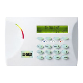
Fire Command Center The XR100FC/XR500FC comes with a built-in LCD display with a 20-key membrane keyboard called the Fire Command Center. The keyboard is mounted behind an opening in the red enclosure door. -
Page 8: The Fire Command Center
This LED is OFF when no alarm currently displays in the status list. There are four keys under the display called the Select keys. They allow you to choose what to do by pressing the Select key under choices being shown in the display. XR100FC/XR500FC User’s Guide Introduction... -
Page 9: Using The Keypad
8 display. Press the COMMAND key to display areas 9 through 16. Press the COMMAND key again to display areas 17 through 25. Press the COMMAND key one more time to display areas 26 through 32. Note: Only areas pre-programmed at installation can display. Introduction XR100FC/XR500FC User’s Guide... -
Page 10: Four Function Keys
At SET VOLUME LEVEL, use the left Select key to lower the keypad volume. Use the right Select key to raise the volume. Model Number The keypad model number, firmware version, and date display, but cannot be changed. XR100FC/XR500FC User’s Guide Introduction... -
Page 11: Special Fire Command Center Displays
A user has attempted a door access to an armed area to which they do not have arming and disarming authority. TROUBLE There is a problem with a protection device or system component. This display is accompanied by a description of the problem. Introduction XR100FC/XR500FC User’s Guide... -
Page 12: Special Fire Command Center Tones
Press a Select key to silence. What to do when the trouble tone sounds You can silence the trouble tone by pressing any key. This only silences the keypad and does not correct the condition that originally caused the trouble. XR100FC/XR500FC User’s Guide Introduction... -
Page 13: Fire Command Center User Menu
Some features displayed on the User Menu are not necessary for the model and version numbers. XR100FC/XR500FC Addressable Fire Alarm Control Panel. Please SYSTEM TEST Tests the system siren, communication disregard these prompts and displays. Press the COMMAND key to to the central station, and backup skip any displays and prompts not discussed in this User Guide. -
Page 14: Alarm Silence
3. The keypad displays SENSORS OFF for five seconds followed 2. The keypad displays ALARM SILENCE?. by SENSORS ON. 3. Press any Select key to silence the bells and exit the User 4. The keypad automatically exits the User Menu. Menu. XR100FC/XR500FC User’s Guide System Setup... -
Page 15: Outputs On Off
8. Press the Back Arrow key to exit the User Menu. Browser Feature unsure output number, refer Appendix B at the back of this guide for a diagram showing you how to use the built-in Outputs ON/OFF browser. System Setup XR100FC/XR500FC User’s Guide... -
Page 16: Zone Status
3b. Select BYPS for a list of zones that are currently bypassed. 3c. Select ALR for a list of zones that have gone into alarm during the current or previous armed period. 3d. Press NBR and ZONE NO: - displays. XR100FC/XR500FC User’s Guide System Setup... -
Page 17: System Status
TEST END to indicate the System Test is complete. VER_201_3/08/04), the panel model (MODEL XR500N), and You can press the Back Arrow key to end the transmit then exits the User Menu. test. * The transmit test does not occur on local systems. System Setup XR100FC/XR500FC User’s Guide... -
Page 18: User Profiles
Note: During the Panic Zone Test, any zones that fail are not sent to the receiver unless pre-programmed at installation to be sent. Always make sure that at least one administrator in your system has a profile with all authorities and all areas. XR100FC/XR500FC User’s Guide System Setup... -
Page 19: User Profiles Reference
TEMP EXPIRE DATE:. Enter the ending date for the profile to RE ARM DLY 0 – 250 Re-Arm Delay expire. Default is seven days from today. The system deletes Temp users at 12:00 AM on the last date. SEC LANGUAGE Preferred Language System Setup XR100FC/XR500FC User’s Guide... -
Page 20: User Codes
Browser Feature Refer to Appendix B in this guide for a diagram showing you how to use the Output Group browser and the Profile browsers. XR100FC/XR500FC User’s Guide System Setup... - Page 21 6 and 7 repeat. The User Profile assignment is automatically selected for the next user based on the previous user entered. This batch entry method speeds up user entry in large systems. System Setup XR100FC/XR500FC User’s Guide...
-
Page 22: Setting The Date And Time
Refer to Appendix B for diagrams showing you how to use the User Press COMMAND. Codes Add, Delete, and Change browsers. The display returns to the TIME DAY DATE display. Press the Back Arrow key to exit the User Menu. XR100FC/XR500FC User’s Guide System Setup... -
Page 23: Ambush Codes
2. The Fire Drill test automatically ends with ALARM SILENCE or system memory. Also, once the full 12,000 events are stored, any the programmed Bell Cutoff time. new event causes the oldest event to be cleared. See Appendix A for Display Events. System Setup XR100FC/XR500FC User’s Guide... -
Page 24: About The Display Events Section
Select PRT to print the complete Display Events log. 4. To use the Sort feature, press the Select key under SRT. The keypad displays FRST DATE: 8/21. Press any Select key and enter a 4-digit beginning date for the sort. Press COMMAND. XR100FC/XR500FC User’s Guide Appendix A... -
Page 25: Zone Event Displays
ALR - Alarm TBL - Trouble RST - Restore FLT - Zone Fault SVC - Service smoke detector LOW - Low battery MIS - Missing wireless transmitter Note: LOW and MIS are for wireless systems only. Appendix A XR100FC/XR500FC User’s Guide... -
Page 26: Supervisory Event Displays
System Monitor Event Names - There are 5 system monitors: POWER - AC power to panel BATTERY - On panel LINE 1 - Phone line number 1 LINE 2 - Phone line number 2 TAMPER - On panel box XR100FC/XR500FC User’s Guide Appendix A... -
Page 27: Zone Status Browser
Appendix B Zone Status Browser Appendix B XR100FC/XR500FC User’s Guide... -
Page 28: Outputs On/Off Browser
Outputs On/Off Browser Output Groups Browser XR100FC/XR500FC User’s Guide Appendix B... -
Page 29: Change User Profiles Browser
Change User Profiles Browser Add User Codes Browser Appendix B XR100FC/XR500FC User’s Guide... -
Page 30: Delete User Codes Browser
Delete User Codes Browser Change User Codes Browser XR100FC/XR500FC User’s Guide Appendix B... -
Page 31: Entering User Names
Entering User Names Appendix B XR100FC/XR500FC User’s Guide... -
Page 32: Common Keypad Displays
The user must exit the area through the proper door. If FAILED TO EXIT attempted to re-enter an area from which they did not not possible, your system administrator should select the exit properly. Forgive option in the User Codes menu. XR100FC/XR500FC User’s Guide Appendix C... - Page 33 Invalid Profile 5 Status LEDs 2 Zone Status 21 Invalid Time 5 Fire Command Center Displays 5 Multi-lingual Option 3 Fire Command Center Tones Service Required 6 Exit 6 Silenced 5 Fire Alarm 6 Supervisory 5 Index XR100FC/XR500FC User’s Guide...
- Page 34 Shfit Schedules 14 Temporary Code 13 Power LED 2 Silence Alarm b Trouble LED 2 Silenced 5 Zone Status 10 Status LEDs 2 Browser 21 System Busy 6 Multi-lingual Display 3 System Status 11 System Test 11 XR100FC/XR500FC User’s Guide Index...
- Page 35 This page intentionally left blank.
- Page 36 LT-1092 1.01 © 2013 Digital Monitoring Products, Inc. 12155...
Need help?
Do you have a question about the XR100FC and is the answer not in the manual?
Questions and answers