
Related Manuals for DMP Electronics SCS-1R


Summary of Contents for DMP Electronics SCS-1R
- Page 1 INST ALLA TION GUIDE SCS-1R SECURITY CONTROL RECEIVER DMP Receiver Help Line Technical Service 1-888-436-7832 International 1-417-831-9362 After hours receiver emergencies 1-417-831-2866...
-
Page 2: Installation Guide
Security Control Receiver Model SCS-1R Installation Guide © 2011 Digital Monitoring Products, Inc. Information furnished by DMP is believed to be accurate and reliable. This information is subject to change without notice. -
Page 3: Table Of Contents
Description ................9 Transmit Level ............... 9 Echo Cancel Off ..............9 Installing the SCS-100 ............9 Connecting the Phone Line ............ 9 Phone Line Monitor..............9 Power Monitor LED ..............9 SCS-100 LEDs ............... 9 Digital Monitoring Products SCS-1R Installation Guide... - Page 4 Printer Cable Pinout ..............16 Security Control Terms Using the LCD Membrane Keypad Special Keys .................17 COMMAND Key ..............17 Back Arrow Key ..............17 Select Keys ...............17 Keypad Prompts Display Current Programming .......17 Entering Alpha Characters .............17 Digital Monitoring Products SCS-1R Installation Guide...
- Page 5 Message Destinations ............35 Printer Troubleshooting Activity Log ERROR ............35 Power Light Not Lit............35 SEL Light Not Lit ...............35 PAPER Light Lit ..............35 Bad Printer Cable ..............35 Notes: ................36 Components Accessory Devices Listings and Approvals Digital Monitoring Products SCS-1R Installation Guide...
-
Page 6: Acknowledging An Alarm Signal
The Green Power LED lights when power is applied to the SCS-1R. The Red ACK LED lights when an alarm signal is received that must be acknowledged. The Red Message LED lights when more than one signal has been received that must be acknowledged. Digital Monitoring Products SCS-1R Installation Guide... -
Page 7: Description
For applications that must conform to a local authorities installation standard or a National Recognized Testing Laboratory certificated system, please see the the Listed Compliance Specifications section near the end of this guide for additional instructions. Digital Monitoring Products SCS-1R Installation Guide... -
Page 8: System Block Diagram
Card 8 Model SCS-104 Line Card Network Connection Model SCS-203 Convenience Panel 3-connector Ribbon Cable Model SCS-204 Host Cable Listed Printer or Membrane Listed Capture Automation Remote Link Keypad and Software Computer 32-Character LCD Programming Digital Monitoring Products SCS-1R Installation Guide... -
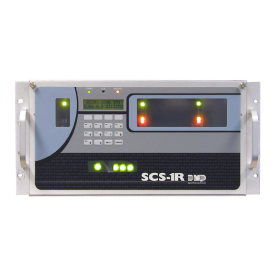
Page 9: Scs-1R Faceplate
After powering up the system, set the correct time, configure the phone lines and network communications. Note: Be sure that the Membrane Keypad is set to Address 01 (one). Refer to LCD Membrane Keypad Configuration for complete information. Digital Monitoring Products SCS-1R Installation Guide... -
Page 10: Scs-1R Components Included
• SCS-RACK with Modem and Multibus Racks, fan, and 32-Character LCD with Membrane Keypad • SCS-150 Receiver Processor Board • SCS-104 Line Card • SCS-110 Modem Supply Card • SCS-120 Multibus Power Supply Card • SCS-130 Transformer Card • SCS-203 Convenience Panel • SCS-208 Power Cord Digital Monitoring Products SCS-1R Installation Guide... -
Page 11: Modem Rack
The SCS-1R must be mounted in a standard 19” rack for listed Fire Signaling applications. Simply slide the entire unit into the 19” rack and secure with screws. Refer to the drawing below for rack-mounting hole locations. SCS-104 Line Cards Rack-Mounting holes SCS-150 Receiver SCS-150 Network Processor Card Connection Digital Monitoring Products SCS-1R Installation Guide... -
Page 12: Compatibility
Set the receiver programming stored in EEPROM to factory defaults 1 1 0 1 Update Software Used for software updates with the SD card 1 1 1 1 Clear Events Clear all pending LCD display, printer, and host output events Digital Monitoring Products SCS-1R Installation Guide... -
Page 13: Reset Programming To Factory Defaults
When finished with the update the SCS-1R display instructs you to remove the SD Card. • Remove the SD card from the SCS-150 and remove the SCS-150 board. • Reset the dip switches to 0000 (OFF OFF OFF OFF) and replace the SCS-150 board and cables. Digital Monitoring Products SCS-1R Installation Guide... -
Page 14: Transmit Level
On when a digital dialer line card has answered the phone line. Ring Detect On when ringing voltage is detected on phone line. Data Terminal Ready On when the line card is ready for operation. Digital Monitoring Products SCS-1R Installation Guide... -
Page 15: Installing The Scs-101
The factory setting is Transmit Data (TXD) on pin #2 and Receive Data (RXD) on pin #3. FORCE CTS The jumpers are set vertically as the factory default. This allows the SCS-101 to tie the CTS and RTS data lines together. Digital Monitoring Products SCS-1R Installation Guide... -
Page 16: Installing The Scs-104
Idle LINE 3 Connected Ringing Idle LINE 4 Connected Ringing Idle LINK Indicates a valid Network connection Indicates a valid Network connection No Connection LINK SPEED Connected at 100 Base-T Connected at 10 Base-T Digital Monitoring Products SCS-1R Installation Guide... -
Page 17: Installing The Scs-110
AC Trouble LED The AC trouble LED lights and the alert tone sounds when AC power to the SCS-130 Transformer Card fails. Silence the alert tone by pressing the silence button on the SCS-110. Digital Monitoring Products SCS-1R Installation Guide... -
Page 18: Installing The Scs-120
Press the SCS-120 power alert silence switch to silence the alert tone. The red TRBL LED remains lit until the power problem is corrected. The modem power LED, the SCS-120 trouble alert tone, and the SCS-110 Modem Power Supply Card power alert LED all operate together. Digital Monitoring Products SCS-1R Installation Guide... -
Page 19: Installation
The 120 VAC connection to the SCS-1R Receiver is current limited with a DMP Model 319, 3 Amp 250 volt fuse. The 3 Amp fuse is a Type AGC 1/4” x 1 1/4” fast blow. Digital Monitoring Products SCS-1R Installation Guide... -
Page 20: Host Cable
If you are using a cable different from the SCS-204, be sure the cable pin out matches the drawing below. SHIELD 2 RXD 2 (3) 3 TXD 3 (2) Connect to HOST COMPUTER (DTE) SIGNAL GROUND 7 (5) MALE DB-25 DB-25 (DB-9) Digital Monitoring Products SCS-1R Installation Guide... -
Page 21: Printer Cable Pinout
User Number - The sequential number assigned to each user code number by the panel during its programming. This is the number transmitted to the SCS-1R Receiver. The actual code number is never transmitted. Digital Monitoring Products SCS-1R Installation Guide... -
Page 22: Special Keys
1, the letters for that key are A, B, and C. Press the first top row Select key for A, the second for B, and the third for C. See the figure below. First Letter Second Letter Third Letter Special Character Entering Alphanumeric Characters Digital Monitoring Products SCS-1R Installation Guide... -
Page 23: Lcd Membrane Keypad Configuration
Arrow and COMMAND keys for two seconds to display SET BRIGHTNESS, enter the code 3577 (INST) and press the COMMAND key. The display changes to KPD OPT (keypad options) KPD DIAG (keypad diagnostics) and STOP. Digital Monitoring Products SCS-1R Installation Guide... -
Page 24: Keypad Options
Exiting the Installer Options When done, press the COMMAND key until the display returns to the Keypad Options and Diagnostics screen. Press the Select key under STOP to exit the Keypad Options and Diagnostics function. Digital Monitoring Products SCS-1R Installation Guide... -
Page 25: Status Displays
ANI/DNIS information is displayed. If ANI/DNIS information is unavailable, then NO DATA will display. Press the COMMAND key to advance to the next DD line card. If no more DD line cards display, the display advances to the programming menu. Digital Monitoring Products SCS-1R Installation Guide... -
Page 26: Scs-150 Programming
Once entered this key does not display and should never be changed. Record this number in the Important information Sheet at the end of this document and store in a secure place. Digital Monitoring Products SCS-1R Installation Guide... - Page 27 Valid range is 1 to 65,535. The default value is 2001. Gateway Address GATEWAY ADDRESS Enter the local SCS-150 GATEWAY ADDRESS. You need the SCS-150 Gateway Address if 000.000.000.000 subnets are divided in your network. The default value is 000.000.000.000. Digital Monitoring Products SCS-1R Installation Guide...
-
Page 28: Line Cards
Identification (ANI) and Dialed Number Identification Service (DNIS) information to be sent. ANI sends the phone number that the panel is using to call. DNIS sends the DNIS identifier of the phone number that the panel dialed. Default is NO. Digital Monitoring Products SCS-1R Installation Guide... -
Page 29: Network Line Setup
See the Substitution Code section of the panel programming guide for the definition of a substituted panel. The SCS-104 generates only one S58 Alarm: Panel Substitution message to the host automation computer and receiver printer for Digital Monitoring Products SCS-1R Installation Guide... -
Page 30: Exiting Network Line Setup
TCP protocol. Select UDP to communicate using UDP protocol. Default is TCP. Start Character START CHARACTER : Enter the character to be used at the start of a host message. Enter None or 01-12 or NONE 14-31. Default is NONE. Digital Monitoring Products SCS-1R Installation Guide... -
Page 31: Serial Ports
Press any top row Select key to enter the new time. Using the Digit keys on the keypad, enter the current time and then press Select key under AM or PM. TIME CHANGED displays after the time has been changed. Digital Monitoring Products SCS-1R Installation Guide... -
Page 32: Exit Programming Menu
Receiver Options This section assigns the company name and system number as well as the IP and Gateway addresses for each SCS-1R Receiver incoming line. Digital Monitoring Products SCS-1R Installation Guide... -
Page 33: Receiver Number
Select to enable monitoring of digital dialer lines for any failed communication attempts. A failed communication attempt occurs when the line card goes off hook but does not successfully communicate with a panel. Default is unchecked (disabled). Digital Monitoring Products SCS-1R Installation Guide... -
Page 34: Print Operation
Note: If Print Operation is set to Always or Primary Fail, ensure that a printer is connected to the printer port. Activity Log Baud Rate Select the baud rate for the Serial Printer port. Default is 1200. Select 300, 600, 1200, 2400, 4800, 9600, 19200, or 38400. Digital Monitoring Products SCS-1R Installation Guide... -
Page 35: Receiver Line Cards
Select DD to enable all dialer lines on the line card to communicate with panels using the DMP digital dialer communication format. Select CID to enable all dialer lines on the line card to communicate with panels using contact ID format. Select NONE to have no second communication type. Default is DD. Digital Monitoring Products SCS-1R Installation Guide... -
Page 36: Scs-104 Network Settings
The Passphrase is blank by default. Note: DO NOT LOSE THE PASSPHRASE. A lost or forgotten Passphrase requires that every XR500 Series panel reporting to the SCS-104 at the receiver be individually reprogrammed with a new passphrase. Digital Monitoring Products SCS-1R Installation Guide... -
Page 37: Scs-104 Check-In Table Settings
The Host Port identifies the port on the host automation computer. Valid range is 1 to 65,535. The default value is 2001. Protocol Select TCP to communicate with the host automation computer over the network using TCP protocol. Select UDP to communicate using UDP protocol. Default is TCP. Digital Monitoring Products SCS-1R Installation Guide... -
Page 38: Receiver Diagnostics
25-pin connector Auxiliary Port on the back of the SCS-1R Receiver using an SCS-204 cable. See Remote Link for more information. Note: Each SCS-150 programming section in Remote Link is independent and changes should be sent to the receiver after programming is completed for each window. Digital Monitoring Products SCS-1R Installation Guide... -
Page 39: Printout Explanations
This message lists the user name accessing the door strike relay and the door number that is being accessed. The door number matches the keypad address operated by the user. This message prints on the Activity Log only. Digital Monitoring Products SCS-1R Installation Guide... -
Page 40: Door Access
Feature or Option Permitted in UL 864? Possible Settings? Settings Permitted in UL 864 Print Operation Always, Never, Fail Always, Fail Digital Monitoring Products SCS-1R Installation Guide... -
Page 41: Notes
Important Information Use the table below to record the reciever key for your SCS-1R Receiver. Keep this sheet and the rest of the manual in a safe location for future reference. Receiver Key __ __ __ __ __ __ __ __ Passphrase __ __ __ __ __ __ __ __ __ __ __ __ __ __ __ __ Notes: Components...
Need help?
Do you have a question about the SCS-1R and is the answer not in the manual?
Questions and answers