Table of Contents
Advertisement
Quick Links
Advertisement
Table of Contents

Related Manuals for Supermicro SBI-7125W-S6


Summary of Contents for Supermicro SBI-7125W-S6
- Page 1 SBI-7125W-S6 Blade Module User’s Manual Revison 1.0...
- Page 2 Please Note: For the most up-to-date version of this manual, please see our web site at www.supermicro.com. Super Micro Computer, Inc. (“Supermicro”) reserves the right to make changes to the product described in this manual at any time and without notice. This product, including software, if any, and documentation may not, in whole or in part, be copied, photocopied, reproduced, translated or reduced to any medium or machine without prior written consent.
-
Page 3: About This Manual
Blade Module. Chapter 3: Setup and Installation Refer to this chapter for details on installing the SBI-7125W-S6 Blade Module into the SuperBladeSuperBlade chassis. Other sections cover the installation and placement of memory modules and the installation of hard disk drives into the blade module. - Page 4 SBI-7125W-S6 Blade Module User’s Manual Notes...
-
Page 5: Table Of Contents
........1-1 1-3 Blade Module Features ..............1-2 Processors ....................1-2 Memory ....................1-2 Storage....................1-3 Density ....................1-3 1-4 Contacting Supermicro ..............1-4 Chapter 2 System Safety ..............2-1 2-1 Electrical Safety Precautions ............2-1 2-2 General Safety Precautions ............. - Page 6 SBI-7125W-S6 Blade Module User’s Manual 3-9 Configuring and Setting up RAID ..........3-11 Chapter 4 Blade Module Features ..........4-1 4-1 Control Panel ..................4-2 Power Button ..................4-3 KVM Button..................... 4-3 LED Indicators ..................4-3 KVM Connector..................4-3 4-2 Mainboard ...................
- Page 7 Using Manual Configuration: RAID 5 ..........5-20 Using Manual Confi guration: RAID 10 ..........5-21 Using Manual Confi guration: RAID 50 ..........5-22 Adding Hotspare Disks................5-23 Changing Adjustable Task Rates ............5-23 Changing Virtual Disk Properties ............5-24 Deleting a Virtual Disk................5-24 Saving a Storage Configuration to Disk ..........
- Page 8 SBI-7125W-S6 Blade Module User’s Manual Notes viii...
- Page 9 Figure 4-2. Blade Control Panel................ 4-2 Figure 4-3. B7DW3 Mainboard ................. 4-4 Figure 4-4. Intel 5400 MCH/ESB2 Chipset: Block Diagram ......4-5 Figure 4-5. Exploded View of SBI-7125W-S6 Blade Module ......4-6 Figure 5-1. Customer Information Screen............5-3 Figure 5-2. Setup Type Screen ................. 5-4 Figure 5-3.
- Page 10 SBI-7125W-S6 Blade Module User’s Manual Notes...
- Page 11 Table 4-3. Blade Module LED Indicators ............4-3 Table 4-4. B7DW3 Mainboard Layout............... 4-5 Table 4-5. Main Components of SBI-7125W-S6 Blade Module......4-7 Table 6-1. Main BIOS Setup Menu Options............6-4 Table 6-2. SATA Port 0/SATA Port 1 Submenu Menu Options ......6-4 Table 6-3.
- Page 12 SBI-7125W-S6 Blade Module User’s Manual Notes...
-
Page 13: Chapter 1 Introduction
The SBI-7125W-S6 blade module is a compact self-contained server that connects into a pre-cabled enclosure that provides power, cooling, management and networking functions. One enclosure for the SBI-7125W-S6 blade module can hold ten blade units. In this manual, “blade system” refers to the entire system (including the enclosure and blades units), “blade”... -
Page 14: Blade Module Features
Please note that you will need to check the detailed specifications of a particular blade module for a list of the CPUs it supports. Details on installation of the processor into the SBI-7125W-S6 blade module are found Chapter 3: "Setup and Installation" on page 3-1. -
Page 15: Storage
Chapter 1: Introduction Storage The SBI-7125W-S6 blade module can have six 2.5-inch SATA (Serial ATA) hard disk drives in front-mounted easy removable carriers. See Chapter 3: "Setup and Installation" on page 3-1 for storage installation details. Density A maximum of ten blade modules may be installed into a single blade enclosure. Each blade enclosure is a 7U form factor, so a standard 42U rack may accommodate up to six enclosures with 60 blade modules, or the equivalent of 60 1U servers. -
Page 16: Contacting Supermicro
SBI-7125W-S6 Blade Module User’s Manual Contacting Supermicro Headquarters Address: Super Micro Computer, Inc. 980 Rock Ave. San Jose, CA 95131 U.S.A. Tel: +1 (408) 503-8000 Fax: +1 (408) 503-8008 marketing@supermicro.com (General Information) Email: support@supermicro.com (Technical Support) Web Site: www.supermicro.com Europe Address: Super Micro Computer B.V. -
Page 17: Chapter 2 System Safety
Chapter 2 System Safety Electrical Safety Precautions Basic electrical safety precautions should be followed to protect yourself from harm and the SuperBlade from damage: • Be aware of how to power on/off the enclosure power supplies and the individual blades as well as the room's emergency power-off switch, disconnection switch or electrical outlet. -
Page 18: General Safety Precautions
SBI-7125W-S6 Blade Module User’s Manual General Safety Precautions Follow these rules to ensure general safety: • Keep the area around the SuperBlade clean and free of clutter. • Place the blade module cover and any system components that have been removed away from the system or on a table so that they won't accidentally be stepped on. -
Page 19: Chapter 3 Setup And Installation
This chapter covers the setup and installation of the blade module and its components. Installing Blade Modules Up to ten SBI-7125W-S6 blade modules may be installed into a single blade enclosure (depending upon your enclosure and blad). Blade modules with Windows and Linux operating systems may be mixed together in the same blade enclosure. -
Page 20: Removing/Replacing The Blade Cover
SBI-7125W-S6 Blade Module User’s Manual Removing a Blade Unit from the Enclosure 1. Power down the blade unit (see "Powering Down a Blade Unit" above). 2. Squeeze both handles to depress the red sections then pull out both handles completely and use them to pull the blade unit from the enclosure. -
Page 21: Figure 3-1. Inserting A Blade Into The Enclosure
Chapter 3: Setup and Installation Figure 3-1. Inserting a Blade into the Enclosure Figure 3-2. Locking the Blade into Position... -
Page 22: Processor Installation
SBI-7125W-S6 Blade Module User’s Manual Processor Installation One or two processors may be installed to the mainboard of each blade unit. See Chapter 1 for general information on the features of the blade unit and the Supermicro web site for further details including processor, memory and operating system support. -
Page 23: Onboard Battery Installation
Chapter 3: Setup and Installation 8. Place the heatsink on the processor then tighten two diagonal screws until snug, then the other two screws. 9. When all four screws are snug, tighten them all to secure the heatsink to the mainboard. -
Page 24: Memory Installation
Populating Memory Slots The mainboard of a SBI-7125W-S6 blade module has eight memory slots, depending upon the blade model. Both interleaved and non-interleaved memory are supported, so you may populate any number of DIMM slots. Populating two slots at a time (DIMM1A + DIMM2A, DIMM3A + DIMM4A, etc.) with memory modules of the same size and of the same type will result in dual-channel, interleaved memory, which is faster than single-channel, non-interleaved memory. -
Page 25: Dimm Installation
Chapter 3: Setup and Installation NOTE: Though multiple DIMM memory module types and speeds may be supported, you need to use DIMM memory modules of the same speed and type. Figure 3-5. 8-slot DIMM Numbering Toward CPU1 DIMM Installation WARNING: Exercise extreme care when installing or removing DIMM modules to prevent any possible damage. -
Page 26: Hard Disk Drive Installation
SBI-7125W-S6 Blade Module User’s Manual Figure 3-6. Installing a DIMM into a Memory Slot DDR2 DIMM To Install: Insert module vertically and press down until it snaps into place. Pay attention to the bottom notch. Top View of DDR2 DIMM Slot... -
Page 27: Figure 3-7. Installing A Hard Drive In A Carrier
Chapter 3: Setup and Installation Installing a Hard Drive 1. Remove a blank drive carrier from the blade (see removal procedure above). 2. Insert a drive into the carrier with the PCB side facing down and the connector end toward the rear of the carrier. 3. -
Page 28: Installing The Operating System
An operating system (OS) must be installed on each blade module. Blades with Microsoft Windows OS and blades with Linux OS can both occupy and operate within the same blade enclosure. Refer to the SuperMicro web site for a complete list of supported operating systems. -
Page 29: Installing Via Virtual Media (Drive Redirection)
Chapter 3: Setup and Installation Installing via Virtual Media (Drive Redirection) You can install the OS via Virtual Media through either the IPMIview (Java based client utility), IPMItool or the Web-based Management Utility. With this method, the OS is installed from an ISO image that resides on another system/blade. Refer to the manuals on your SuperBlade CD-ROM for further details on the Virtual Media (CD-ROM or Drive Redirection) sections of these two utility programs. - Page 30 SBI-7125W-S6 Blade Module User’s Manual Notes 3-12...
-
Page 31: Chapter 4 Blade Module Features
Chapter 4 Blade Module Features Figure 4-1. SBI-7125W-S6 Blade Unit Front View This chapter describes the SBI-7125W-S6 blade unit. Installation and maintenance should be performed by experienced technicians only. Figure 4-1 for a front view of the blade unit and Table 4-1 for its features. -
Page 32: Control Panel
SBI-7125W-S6 Blade Module User’s Manual Control Panel Each blade has a similar control panel (Figure 4-2) with power on/off button, a KVM connector, a KVM button and four LEDs on the top front of the unit. The numbers mentioned in... -
Page 33: Power Button
Chapter 4: Blade Module Features Power Button Each blade has its own power button so that individual blade units within the enclosure may be turned on or off independently of the others. Press the power button (#1) to turn on the blade server. The power LED (#3) will turn green. To turn off, press and hold the power button for >4 seconds and the power LED will turn orange. -
Page 34: Mainboard
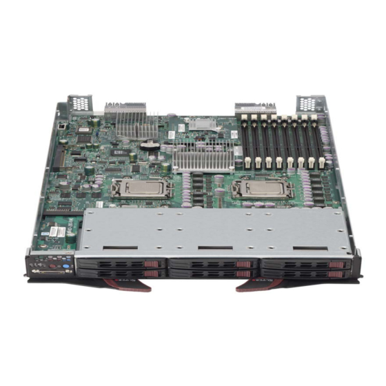
SBI-7125W-S6 Blade Module User’s Manual Mainboard The mainboard of the SBI-7125W-S6 blade unit is a proprietary design, which is based on the Intel 5400 MCH/ESB2 chipset. See Figure 4-4 for a block diagram of this chipset, Figure 4-3 for a view of the B7DW3 Mainboard and... -
Page 35: Figure 4-4. Intel 5400 Mch/Esb2 Chipset: Block Diagram
Chapter 4: Blade Module Features Table 4-4. B7DW3 Mainboard Layout Item Description LGA 771 CPU Sockets FBD (Fully Buffered DIMM) Slots 6 2.5” SAS/SATA Hard Drive Bays SIMBL Slot InfiniBand Connectors (for InfiniBand cards - not shown) Gbx Connectors (for power and logic to backplane) Intel (ESB2) 82563EB (South Bridge chip) Intel 5400 (North Bridge chip) Onboard Battery... -
Page 36: Jumpers
Short the CMOS pads with a metal object such as a small screwdriver. 3. Replace the cover, install the blade back into the enclosure and power it on. Blade Unit Components Figure 4-5. Exploded View of SBI-7125W-S6 Blade Module... -
Page 37: Memory Support
Air Shroud 1 Air Shroud 2 Air Shroud 3 Memory Support The SBI-7125W-S6 blade module supports up to 64 GB of ECC FBD DDR2-800/667/ 533 SDRAM in eight DIMM sockets. See Section 3-5 for further details on mainboard memory installation. - Page 38 SBI-7125W-S6 Blade Module User’s Manual Notes...
-
Page 39: Chapter 5 Raid Setup Procedure
Chapter 5 RAID Setup Procedure RAID setup for the SBI-7125W-S6 blade module is done using the MegaRAID Storage Manager software utility. MegaRAID Storage Manager software is a configuration and monitoring utility used with the Embedded MegaRAID Software. This section provides a brief overview of the MegaRAID Storage Manager software and explains how to install it on the supported operating systems. -
Page 40: Maintaining Storage Configurations
SBI-7125W-S6 Blade Module User’s Manual Maintaining Storage Configurations You can use MegaRAID Storage Manager software to perform system maintenance tasks such as running consistency checks on arrays that support redundancy. Hardware and Software Requirements The hardware requirements for MegaRAID Storage Manager software are as follows: •... -
Page 41: Figure 5-1. Customer Information Screen
Chapter 5: RAID Setup Procedure Figure 5-1. Customer Information Screen... -
Page 42: Figure 5-2. Setup Type Screen
SBI-7125W-S6 Blade Module User’s Manual 4. In the C screen enter your user name and organization name. USTOMER NFORMATION In the bottom part of the screen select an installation option: • If you select A , any user with administrative privileges can use this ver-... -
Page 43: Installing Megaraid Storage Manager For Linux
Chapter 5: RAID Setup Procedure 6. In the S screen select one of the Setup options. The options are fully ETUP explained in the screen text. • Select C if you are installing MegaRAID Storage Manager software on OMPLETE a server. •... -
Page 44: Linux Error Messages
SBI-7125W-S6 Blade Module User’s Manual If you select Client installation for a PC used to monitor servers, and if there are no available servers with a registered framework on the local subnet (that is, servers with a complete installation of MegaRAID Storage Manager software), you cannot connect to a remote server unless you first edit the startupui.sh file. -
Page 45: Megaraid Storage Manager Window And Menus
Chapter 5: RAID Setup Procedure MegaRAID Storage Manager Window and Menus This chapter explains how to start MegaRAID Storage Manager software and describes the MegaRAID Storage Manager window and menus. Starting MegaRAID Storage Manager Software Follow these steps to start MegaRAID Storage Manager software and view the main window: 1. -
Page 46: Figure 5-4. Server Login Window
SBI-7125W-S6 Blade Module User’s Manual 2. In the S window if the circle in the server icon is yellow instead of ELECT ERVER green, it means that the server is running in a degraded state—for example, because a disk drive used in a virtual disk has failed. If the circle is red, the storage configuration in the server has failed. -
Page 47: Megaraid Storage Manager Window
Chapter 5: RAID Setup Procedure MegaRAID Storage Manager Window Figure 5-5. MegaRAID Storage Manager Window This section describes the M RAID S window (Figure 5-5). TORAGE ANAGER The following topics describe the panels and menu options that appear in this window. Physical/Logical View Panel The left panel of the MegaRAID Storage Manager window displays either the P HYSICAL... -
Page 48: Properties/Operations/Graphical View Panel
SBI-7125W-S6 Blade Module User’s Manual The following icons in the left panel represent the controllers, disk drives, and other devices: • System • Controller • Port • Array • Virtual disk • Physical drive A red circle to the right of an icon indicates that the device has failed. - Page 49 Chapter 5: RAID Setup Procedure Operations Menu The O menu is available when a controller, physical drive, or logical drive is PERATIONS selected in the M RAID S window. The O menu options TORAGE ANAGER PERATIONS vary depending on what type of device is selected in the left panel of the M RAID window.
-
Page 50: Configuration
SBI-7125W-S6 Blade Module User’s Manual Configuration You use MegaRAID Storage Manager software to create and modify storage configurations. RAID 0, RAID 1, RAID 5, RAID 6, RAID 10, RAID 50, and RAID 60 storage configurations are supported. WARNING: LSI recommends that you do not use both SAS and SATA drives in the same array. -
Page 51: Understanding Virtual Disk Parameters
Chapter 5: RAID Setup Procedure This screen lists three configuration modes that you can select from: • automatically creates an optimal confi guration from the ONFIGURATION available disk drives. • gives you the greatest level of control in creating a new ANUAL ONFIGURATION virtual disk. -
Page 52: Using Auto Configuration
SBI-7125W-S6 Blade Module User’s Manual Using Auto Configuration Figure 5-7. Auto Configuration Screen Selecting A mode brings up the A screen ONFIGURATION ONFIGURATION (Figure 5-7). is the quickest and simplest way to create a new storage ONFIGURATION configuration. When you select A... -
Page 53: Using Guided Configuration
Chapter 5: RAID Setup Procedure • Full Initialization: A complete initialization is done on the new configuration. This may take a long time if the disks are large. 3. (Optional) Click M if you want to switch to M mode so ODIFY ANUAL ONFIGURATION... -
Page 54: Figure 5-9. Virtual Disk Parameters Screen
SBI-7125W-S6 Blade Module User’s Manual • Redundancy when possible: Create a redundant configuration if possible. Otherwise, create a non-redundant configuration. • No Redundancy: Create a non-redundant configuration. 2. Choose whether you want to use existing arrays in the new virtual disk. The options are: •... -
Page 55: Using Manual Confi Guration: Raid 0
Chapter 5: RAID Setup Procedure NOTE: You could do this to leave capacity available for other virtual disks that you create later. 6. Click N to continue to the next screen. 7. Check the configuration that you have just defined. If it is acceptable, click F . -
Page 56: Figure 5-11. Virtual Disk Creation Screen
SBI-7125W-S6 Blade Module User’s Manual NOTE: To remove a single drive from a proposed new array, select the drive icon in the right panel and click the L button. RROW 3. Click N The V screen appears, as shown in Figure 5-11. -
Page 57: Using Manual Configuration: Raid 1
Chapter 5: RAID Setup Procedure 9. Click N to continue with the next configuration step. The V IRTUAL UMMARY screen appears. 10. Review the configuration shown in the V screen. If you want to IRTUAL UMMARY change something, click B and change the configuration parameters. -
Page 58: Using Manual Configuration: Raid 5
SBI-7125W-S6 Blade Module User’s Manual 4. To remove a hotspare from an array, select it in the right panel and click R EMOVE PARE 5. Click N The V screen appears, as shown in Figure 5-11. IRTUAL REATION 6. The A... -
Page 59: Using Manual Confi Guration: Raid 10
Chapter 5: RAID Setup Procedure 3. Click N The V screen appears (Figure 5-11). IRTUAL REATION 4. The A menu lists the new array that you just defined, plus RRAYS WITH PACE any existing arrays with holes (free space) that could be used for a new configuration. -
Page 60: Using Manual Confi Guration: Raid 50
SBI-7125W-S6 Blade Module User’s Manual 7. The A menu lists the new array that you just defined, plus RRAYS WITH PACE any existing arrays with holes (free space) that could be used for a new configuration. In the left panel, select the two RAID 1 arrays from the menu. -
Page 61: Adding Hotspare Disks
Chapter 5: RAID Setup Procedure For a RAID 10 array, the entire capacity of the array is automatically used for the new virtual disk. You cannot defi ne another virtual disk on this array. 10. (Optional) Change the other V , if necessary. -
Page 62: Changing Virtual Disk Properties
SBI-7125W-S6 Blade Module User’s Manual 4. Click G to accept the new task rates. 5. When the warning message appears, click OK to confirm that you want to change the task rates. Changing Virtual Disk Properties You can change a virtual disk’s R... -
Page 63: Saving A Storage Configuration To Disk
Chapter 5: RAID Setup Procedure Saving a Storage Configuration to Disk You can save an existing controller confi guration to a file so you can apply it to another controller. To save a configuration file, follow these steps: 1. Select a controller icon in the left panel of the M RAID S TORAGE ANAGER... - Page 64 SBI-7125W-S6 Blade Module User’s Manual To add a saved configuration, follow these steps: 1. Select a controller icon in the left panel of the M RAID S TORAGE ANAGER window. 2. On the menu bar, select O PERATIONS DVANCED PERATIONS...
-
Page 65: Chapter 6 Bios
NOTE: Due to periodic changes to the BIOS, some settings may have been added or deleted and might not yet be recorded in this manual. Please refer to http://www.supermicro.com/products/SuperBlade/module/ web site for further details on BIOS setup and the BIOS menus for your SuperBlade blade module. -
Page 66: Bios Updates
SBI-7125W-S6 Blade Module User’s Manual BIOS Updates It may be necessary to update the BIOS used in the blade modules on occasion. However, it is recommended that you not update BIOS if you are not experiencing problems with a blade module. -
Page 67: Running Setup
Chapter 6: BIOS 3. Go to the V menu and select F IRTUAL EDIA LOPPY MAGE PLOAD 4. B or O to locate the *.img file on your desktop and select it. ROWSE 5. Press the U button and wait a few seconds for the image to upload to the PLOAD CMM. -
Page 68: Main Bios Setup
SBI-7125W-S6 Blade Module User’s Manual Main BIOS Setup All main Setup options are described in this section. Use the U arrow keys to move among the different settings in each menu. Use the L arrow keys to change the options for each setting. -
Page 69: Advanced Setup
Chapter 6: BIOS Table 6-2. SATA Port 0/SATA Port 1 Submenu Menu Options (Continued) Menu Option Description This option allows the user to select Ultra DMA Mode. The options are Disabled, Ultra DMA Mode Mode 0, Mode 1, Mode 2, Mode 3, Mode 4 and Mode 5. This setting allows the user to enable or disable Parallel ATA. -
Page 70: Table 6-3. Advanced Setup Menu Options
SBI-7125W-S6 Blade Module User’s Manual Table 6-3. Advanced Setup Menu Options Submenu Description Access this submenu to make changes to boot features. See Table 6-4 for a list Boot Features of menu options in this submenu. Access this submenu to make changes to settings for the memory cache. See... -
Page 71: Table 6-5. Memory Cache Submenu Menu Options
Chapter 6: BIOS Table 6-5. Memory Cache Submenu Menu Options Menu Option Description This setting allows you to designate a reserve area in the system memory to be used as a system BIOS buffer into which the BIOS will write (cache) its data. Cache System BIOS Select Write Protect to enable this function, and this area will be reserved for Area... -
Page 72: Table 6-6. Pci Configuration Submenu Menu Options
SBI-7125W-S6 Blade Module User’s Manual Table 6-6. PCI Configuration Submenu Menu Options Menu Option Description Onboard GLAN1/ Onboard GLAN2 Enabling this option provides the capability to boot from an Ethernet port. The (Gigabit- LAN) options are Enabled and Disabled. OPROM Configure Default Primary Video Choose the default video adapter. -
Page 73: Table 6-8. Advanced Processor Options Submenu Menu Options
Chapter 6: BIOS Table 6-7. Advanced Chipset Control Submenu Menu Options (Continued) Menu Option Description High Bandwidth FSB Select Enabled to enable a high bandwidth FSB or Disable to disable it. High Temp DRAM OP Select Enabled to enable a high temp DRAM OP or Disable to disable it. ABM Thermal Sensor Select Enabled to enable the ABM thermal sensor or Disable to disable it. -
Page 74: Table 6-9. I/O Device Configuration Submenu Menu Options
SBI-7125W-S6 Blade Module User’s Manual Table 6-8. Advanced Processor Options Submenu Menu Options (Continued) Menu Option Description C1 Enhanced Mode Set to Enabled to enable Enhanced Halt State to lower the CPU voltage/ (Available when frequency to prevent overheating. The options are Enabled and Disabled. -
Page 75: Table 6-10. Console Redirection Submenu Menu Options
Chapter 6: BIOS Table 6-9. I/O Device Configuration Submenu Menu Options (Continued) Menu Option Description DMI Event Logging Access the submenu to make changes to the following settings. Event Log Validity This is a display to inform you of the event log validity. It is not a setting. Event Log This is a display to inform you of the event log capacity. -
Page 76: Security
SBI-7125W-S6 Blade Module User’s Manual Table 6-11. Hardware Monitor Submenu Menu Options Menu Option Description This option allows the user to set a CPU temperature threshold that will activate the alarm system when the CPU temperature reaches this pre-set temperature threshold. -
Page 77: Boot
Chapter 6: BIOS Boot Choose Boot from the Phoenix BIOS Setup Utility main menu with the arrow keys. Highlighting a setting with a + or - will expand or collapse that entry. See details on how to change the order and specs of boot devices in the I window. - Page 78 SBI-7125W-S6 Blade Module User’s Manual Notes 6-14...
-
Page 79: Appendix Abios Post Codes
Appendix A BIOS POST Codes BIOS POST Messages During the Power-On Self-Test (POST), the BIOS will check for problems. If a problem is found, the BIOS will activate an alarm or display a message. The following is a list of such BIOS messages. - Page 80 SBI-7125W-S6 Blade Module User’s Manual Table A-1. BIOS POST Messages (Continued) BIOS Message Description Previous POST did not complete successfully. POST loads default values and offers to run Setup. If the failure was caused by incorrect values and they are not corrected, the next boot Previous boot incomplete - Default will likely fail.
-
Page 81: A-2 Bios Post Codes
Table A-1. BIOS POST Messages (Continued) BIOS Message Description Where nnnn is the amount of RAM in kilobytes successfully nnnn kB Extended RAM Passed tested. Where nnnn is the amount of system cache in kilobytes nnnn Cache SRAM Passed successfully tested. Where nnnn is the amount of shadow RAM in kilobytes nnnn kB Shadow RAM Passed successfully tested. -
Page 82: Recoverable Post Errors
SBI-7125W-S6 Blade Module User’s Manual Recoverable POST Errors When a recoverable type of error occurs during POST, the BIOS will display an POST code that describes the problem. BIOS may also issue one of the following beep codes: • One long and two short beeps – video configuration error •... - Page 83 Table A-2. Terminal POST Errors (Continued) Post Code Description 1-3-1-3 Test 8742 Keyboard Controller Auto size DRAM Initialize POST Memory Manager Clear 512 kB base RAM 1-3-4-1 RAM failure on address line xxxx* 1-3-4-3 RAM failure on data bits xxxx* of low byte of memory bus Enable cache before system BIOS shadow Test CPU bus-clock frequency Initialize Phoenix Dispatch Manager...
- Page 84 SBI-7125W-S6 Blade Module User’s Manual Table A-2. Terminal POST Errors (Continued) Post Code Description Test RAM between 512 and 640 kB Test extended memory Test extended memory address lines Jump to UserPatch1 Configure advanced cache registers Initialize Multi Processor APIC...
- Page 85 Table A-2. Terminal POST Errors (Continued) Post Code Description Build MPTABLE for multi-processor boards Install CD ROM for boot Clear huge ES segment register 1-2 Search for option ROMs. One long, two short beeps on check-sum failure Check for SMART Drive (optional) Shadow option ROMs Set up Power Management Initialize security engine (optional)
-
Page 86: Table A-3. Boot Block Flash Rom Terminal Post Errors
SBI-7125W-S6 Blade Module User’s Manual Table A-2. Terminal POST Errors (Continued) Post Code Description Initialize system error handler PnPnd dual CMOS (optional) Initialize note dock (optional) Initialize note dock late Force check (optional) Extended checksum (optional) Redirect Int 15h to enable remote keyboard... - Page 87 Table A-3. Boot Block Flash ROM Terminal POST Errors (Continued) Post Code Description Initialize video Initialize System Management Manager Output one beep Clear Huge Segment Boot to Mini DOS Boot to Full DOS If the BIOS detects error 2C, 2E, or 30 (base 512K RAM error), it displays an additional word-bitmap ( ) indicating the address line or bits that failed.
- Page 88 SBI-7125W-S6 Blade Module User’s Manual Notes A-10...
-
Page 89: Appendix B Iscsi Setup Procedure
Appendix B iSCSI Setup Procedure This appendix covers the iSCSI setup procedure for Supermicro blade systems. If you do not wish to employ this optional interface for your blades, then skip this procedure in your blade setup. NOTE: iSCSI installation requires two (2) network switch/pass-thru modules to implement. -
Page 90: Figure B-1. Microsoft Mpio Multipathing Support For Iscsi Check Box
SBI-7125W-S6 Blade Module User’s Manual 8. Copy the following Windows drivers to your desktop (or a convenient directory for later reference and use): • Intel Network Driver • Microsoft iSCSI Software Initiator with integrated software boot support • ISBOOT.exe 9. Bring up the W... -
Page 91: Figure B-2. Configure Iscsi Network Boot Support Check Box
Figure B-2. Configure iSCSI Network Boot Support Check Box c. In the next screen select A GREE d. In the final screen, click F INISH 12. Reboot the system. 13. Launch the ISBOOT.exe file. It will create an Intel12.3 folder on your system. In this new folder look for either the WIN32 folder for 32-bit Windows installation, or the WINX64 folder for 64-bit installation. - Page 92 SBI-7125W-S6 Blade Module User’s Manual 19. Open the W terminal window and type INDOWS OMMAND ROMPT iscsibcg /verify /fix in the window and press <E >. NTER 20. Reboot the system.
- Page 93 Disclaimer The products sold by Supermicro are not intended for and will not be used in life support systems, medical equipment, nuclear facilities or systems, aircraft, aircraft devices, aircraft/emergency communication devices or other critical systems whose failure to perform be reasonably expected to result in significant injury or loss of life or catastrophic property damage.
- Page 94 SBI-7125W-S6 Blade Module User’s Manual...
Need help?
Do you have a question about the SBI-7125W-S6 and is the answer not in the manual?
Questions and answers