
Related Manuals for Supermicro SuperBlade SBI-6119R-C3N


Summary of Contents for Supermicro SuperBlade SBI-6119R-C3N
- Page 1 SuperBlade ® SBI-6119R-C3N SBI-6119R-T3N SBI-6119R-C3N SBI-6119R-T3N USER’S MANUAL Revision 1.0...
- Page 2 State of California, USA. The State of California, County of Santa Clara shall be the exclusive venue for the resolution of any such disputes. Supermicro's total liability for all claims will not exceed the price paid for the hardware product.
- Page 3 If you have any questions, please contact our support team at: support@supermicro.com This manual may be periodically updated without notice. Please check the Supermicro website for possible updates to the manual revision level. Warnings Special attention should be given to the following symbols used in this manual.
-
Page 4: Table Of Contents
Preface Contents Chapter 1 Introduction 1.1 Overview ..........................8 1.2 Product Checklist of Typical Components ................8 1.3 Blade Module Features ......................9 Processors ..........................9 Memory ..........................9 Storage ..........................10 RAID ..........................10 Enclosure Requirements ....................10 Density ..........................11 Chapter 2 Setup and Installation 2.1 Overview ..........................12 2.2 Installing Blade Modules ....................12 Powering Up a Blade Unit....................12 Powering Down a Blade Unit ....................12... - Page 5 SuperBlade SBI-6119R-C3N/T3N User's Manual 2.9 Configuring and Setting up RAID ..................25 Chapter 3 Blade Module Features 3.1 Control Panel ........................27 Power Button ........................27 3.2 Motherboard ........................28 CMOS Clear ........................31 Jumper Settings ........................31 3.3 Blade Unit Components .....................32 Memory Support ........................33 Hard Disk Drives .......................33...
- Page 6 Preface T1s Auto Configuration......................52 4.6 Event Logs Setup .......................53 4.7 IPMI Setup ..........................55 4.8 Security Setup ........................57 4.9 Boot Setup ..........................59 4.10 Save & Exit ........................61 Appendix A Updating BIOS Using KVM Console Appendix B Standardized Warning Statements for AC Systems B.1 About Standardized Warning Statements ................70...
- Page 7 SuperBlade SBI-6119R-C3N/T3N User's Manual Contacting Supermicro Headquarters Address: Super Micro Computer, Inc. 980 Rock Ave. San Jose, CA 95131 U.S.A. Tel: +1 (408) 503-8000 Fax: +1 (408) 503-8008 Email: marketing@supermicro.com (General Information) support@supermicro.com (Technical Support) Website: www.supermicro.com Europe Address: Super Micro Computer B.V.
-
Page 8: Chapter 1 Introduction
If you have any questions, please contact our support team at: support@supermicro.com A complete list of safety warnings is provided on the Supermicro website at http://www.supermicro.com/about/policies/safety_information.cfm. 1.2 Product Checklist of Typical Components Your blade module ships with its B11SRE-CPU mainboard already installed in its chassis. -
Page 9: Blade Module Features
The SBI-6119R-C3N/T3N SuperBlade module supports a single Intel Xeon W-2100 series, Socket R4 LGA 2066 series processor. Refer to the Supermicro website for a complete listing of supported processors (http://www. supermicro.com/products/superblade). Please note that you will need to check the detailed specifications of a particular blade module for a list of the CPUs it supports. -
Page 10: Storage
SuperBlade SBI-6119R-C3N/T3N User's Manual Please refer to the Supermicro website for a list of supported memory (www.supermicro.com/ products/superblade). The detailed specifications for a blade module will contain a link to a list of recommended memory sizes and manufacturers. Details on installation of memory modules into the SBI-6119R-C3N/T3N SuperBlade module are found in Chapter 2: "Setup and Installation". -
Page 11: Density
Chapter 1: Introduction Density A maximum of 10 SBI-6119R-C3N/T3N blade modules may be installed into a single blade enclosure. Each blade enclosure is a 6U form factor, so a standard 42U rack may accommodate up to seven enclosures with 70 blade modules, or the equivalent of 70 1U servers. With the inclusion of fourteen CMM modules and twenty-eight 1G/10G Ethernet switches, this would occupy up to 98U space in a conventional 1U server configuration. -
Page 12: Chapter 2 Setup And Installation
SuperBlade SBI-6119R-C3N/T3N User's Manual Chapter 2 Setup and Installation 2.1 Overview This chapter covers the setup and installation of the blade module and its components. Please refer to Appendix B, Standardized Warning Statements for AC Systems before installing the system or components in this chapter. -
Page 13: Installing A Blade Unit Into The Enclosure
Chapter 2: Server Installation 2. Squeeze the handle to depress the red section then pull out the blade unit from the enclosure using the handle. Note: Blade Modules can be Hot-Plugged from the enclosure. Installing a Blade Unit into the Enclosure Installing a Blade Unit into the Enclosure 1. -
Page 14: Processor And Heatsink Installation
CPU socket cap is in place and that none of the socket pins are bent; otherwise, contact your retailer immediately. 3. Refer to the Supermicro website for updates on CPU support. 4. Please follow the instructions given in the ESD Warning section on the first page of this chapter before handling, installing, or removing system components. - Page 15 Chapter 2: Server Installation 2. Press the second load lever labeled 'Close 1st' to release the load plate that covers the CPU socket from its locking position. Press down on Load the Pull lever away from the Lever labeled 'Close 1st' socket 3.
- Page 16 SuperBlade SBI-6119R-C3N/T3N User's Manual 5. Use your thumb and index finger to hold the CPU on its edges. Align the CPU keys, which are semi-circle cutouts, against the socket keys. Socket Keys CPU Keys 6. Once they are aligned, carefully lower the CPU straight down into the socket. (Do not drop the CPU on the socket.
- Page 17 Chapter 2: Server Installation 7. With the CPU inside the socket, inspect the four corners of the CPU to make sure that the CPU is properly installed. 8. Close the load plate with the CPU inside the socket. Lock the lever labeled 'Close 1st' first, then lock the lever labeled 'Open 1st' second.
-
Page 18: Installing A Passive Cpu Heatsink
SuperBlade SBI-6119R-C3N/T3N User's Manual Installing a Passive CPU Heatsink 1. Do not apply any thermal grease to the heatsink or the CPU die -- the required amount has already been applied. 2. Place the heatsink on top of the CPU so that the four mounting holes are aligned with those on the motherboard and the heatsink bracket underneath. -
Page 19: Removing The Cpu And The Heatsink
Chapter 2: Server Installation Removing the CPU and the Heatsink Warning: We do not recommend that the CPU or the heatsink be removed. However, if you do need to uninstall the CPU or the heatsink, please follow the instructions below to uninstall the heatsink or the CPU without damaging the CPU or the motherboard. -
Page 20: Memory Installation
64GB 64GB 64GB 64GB 64GB 512GB Check the Supermicro website for possible updates to memory support. Memory Population Guidelines • All DIMMs must be DDR4. • Balance memory. Using unbalanced memory topology, such as populating two DIMMs in one channel while populating one DIMM in another channel, reduces performance. It is not recommended for Supermicro systems. -
Page 21: Memory Population Sequence
Then, if using two DIMMs per channel, install the second DIMM in the black slot. The following memory population sequence table was created based on guidelines provided by Intel to support Supermicro motherboards. The diagram is for illustrative purposes; your motherboard may look different. -
Page 22: Installing Memory
SuperBlade SBI-6119R-C3N/T3N User's Manual Installing Memory ESD Precautions Electrostatic Discharge (ESD) can damage electronic com ponents including memory modules. To avoid damaging DIMM modules, it is important to handle them carefully. The following measures are generally sufficient. • Use a grounded wrist strap designed to prevent static discharge. -
Page 23: Usb Memory Stick Installation
6. Push the handle in until you hear the carrier click into its locked position. Caution: Enterprise level hard disk drives are recommended for use in Supermicro chassis and servers. For information on recommended HDDs, visit the Supermicro website at http://www. -
Page 24: Installing The Operating System
Windows OS and blades with Linux OS can both occupy and operate within the same blade enclosure. Refer to the SuperMicro website for a complete list of supported operating systems. There are several methods of installing an OS to the blade modules. -
Page 25: Installing Via Virtual Media (Drive Redirection)
The procedures for doing this vary depending upon the blade model chosen for your SuperBlade system. For this module RAID 0, 1 and 5 is available for each node. For RAID setup see http://www.supermicro.com/support/manuals/ under RAID Installation Guides for more details. -
Page 26: Chapter 3 Blade Module Features
SuperBlade SBI-6119R-C3N/T3N User's Manual Chapter 3 Blade Module Features This chapter describes the SBI-6119R-C3N/T3N blade modules. Installation and maintenance should be performed by experienced technicians only. See Figure 3-1 for a front view of the blade units and the table below for their features. -
Page 27: Control Panel
Chapter 3: Maintenance and Component Installation 3.1 Control Panel Each blade has a similar control panel (Figure 3-2) with power on/off button, a KVM connector, a KVM button and four LEDs on the top front of the unit. The numbers mentioned in Figure 3-2 are described in the table below. -
Page 28: Motherboard
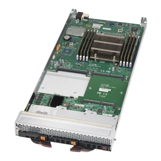
SuperBlade SBI-6119R-C3N/T3N User's Manual 3.2 Motherboard The motherboard of the SBI-6119R-C3N/T3N blade unit is a proprietary design, which is based on the Intel C422 chipset. See Figure 3-5 for a block diagram of this chipset, Figure 3-3 for a top-down view of the SBI-6119R-C3N module and Figure 3-4 for the SBI-6119R-T3N module. - Page 29 Chapter 3: Maintenance and Component Installation SBI-6119R-C3N Module Layout Item Description CPUs installed (see Figure 4-3 for details on CPU numbering) Front housing for three 2.5" SATA3/SSD/NVMe hard drive bays DIMM slots (see Figure 4-3 for details, eight total) Power and Logic connectors to backplane Storage Module Compute Module SATA Port...
- Page 30 SuperBlade SBI-6119R-C3N/T3N User's Manual SBI-6119R-T3N Module Layout Item Description CPUs installed (see Figure 4-3 for details on CPU numbering) Front housing for three 2.5" SATA3/SSD/NVMe hard drive bays DIMM slots (see Figure 4-3 for details, eight total) Power and Logic connectors to backplane...
-
Page 31: Cmos Clear
Chapter 3: Maintenance and Component Installation CMOS Clear JBT1 is used to clear CMOS and will also clear any passwords. This consists of two contact pads located near the BIOS chip. Clearing CMOS 1. First power down the blade and remove it from the enclosure. 2. -
Page 32: Blade Unit Components
SuperBlade SBI-6119R-C3N/T3N User's Manual 3.3 Blade Unit Components Figure 3-6. Exploded View of the SBI-6119R-C3N/T3N Blade Modules Main Components of the SBI-6119R-C3N/T3N Blade Modules Item Description Heatsink DIMM slots (8) Drive Bay Connectors... -
Page 33: Memory Support
Caution: To maintain proper airflow, both hard drive bays must have drive carriers inserted during operation whether or not a drive is installed in the tray. Warning: Enterprise level hard disk drives are recommended for use in Supermicro chassis and servers. For information on recommended HDDs, visit the Supermicro website at http:// www.supermicro.com/products/nfo/storage.cfm. -
Page 34: Chapter 4 Bios
SuperBlade SBI-6119R-C3N/T3N User's Manual Chapter 4 BIOS 4.1 Introduction This chapter describes the BIOS for Intel SuperBlade modules. The Blade modules use a 32 Mb SPI Flash EEPROM with AMI® BIOS that is stored in a flash chip. This BIOS can be easily upgraded using a floppy disk-based program. -
Page 35: Bios Updates
BIOS if you are not experiencing problems with a blade module. Updated BIOS files are located on our website (www.supermicro.com/products/superblade/). Please check the current BIOS revision and make sure it is newer than your current BIOS before downloading. -
Page 36: Main Bios Setup
SuperBlade SBI-6119R-C3N/T3N User's Manual 4.4 Main BIOS Setup Figure 4-1. Main BIOS Setup Screen All Main Setup options are described in this section. Use the Up/Down arrow keys to move among the different settings in each menu. Use the Left/Right arrow keys to change the options for each setting. -
Page 37: Advanced Settings Menu
Chapter 4: BIOS BIOS Information BIOS static display information including the motherboard number, SMC version, SMC Build Date and Total Memory is also shown on the screen. 4.5 Advanced Settings Menu Figure 4-2. Advanced BIOS Setup Screen Choose Advanced from the BIOS Setup Utility main menu with the arrow keys to display the Advanced Setup menu. -
Page 38: Pch-Fw Configuration Sub-Menu
SuperBlade SBI-6119R-C3N/T3N User's Manual Quiet Boot When Disabled the BIOS displays normal POST messages. When Enabled the BIOS displays an OEM Logo instead of POST messages. Bootup NUM-Lock State This setting selects the Power-On state for Numlock. Options include On or Off. -
Page 39: Cpu Configuration Sub-Menu
Chapter 4: BIOS CPU Configuration sub-menu Processor Configuration Information This section shows static information on the processor configuration. Hyper-threading [ALL] This setting is Enabled for Windows XP and Linux (OS optimized for Hyper-threading technology), and Disabled for other OSes (any OS not optimized for Hyper-threading techology). - Page 40 SuperBlade SBI-6119R-C3N/T3N User's Manual LLC Prefetch This setting allows you to Enable or Disable the LLC Prefetch on all threads. DCU Mode This sets the DCU mode to either 32KB 8Way Without the ECC or 16KB 4Way With ECC. Extended APIC...
- Page 41 Chapter 4: BIOS CPU C State Control Use this submenu to select a CPU C-State controls. Autonomous Core C-State This setting allows you to Enable or Disable the Autonomous Core C-State control for your system. CPU C6 Report This setting allows you enable/disable a CPU C6 (ACPI C3) report to the OS. Options include Disable, Enable and Auto.
- Page 42 SuperBlade SBI-6119R-C3N/T3N User's Manual MC BGF Threshold The HA to MC BGF threshold is used for scheduling MC requests in bypass condition. Use your keyboard to enter in a number for the threshold. The default is 0. DLL Reset Test Set this to the number of loops to execute the DDL reset test.
- Page 43 Chapter 4: BIOS uCPU1 Configuration This submenu allows you to configure CPU1 configuration options. IOU0 (IIO PCIe Br1) This setting selects the PCIe port bifurcation for Br1. Options include x4x4x4x4, x4x4x8, x8x4x4, x8x8, x16 or Auto. IOU1 (IIO PCIe Br2) This setting selects the PCIe port bifurcation for Br2.
- Page 44 SuperBlade SBI-6119R-C3N/T3N User's Manual Interrupt Remapping This setting allows you to Enable or Disable the VT_D Interrupt Remapping support. PassThrough DMA This setting allows you to Enable or Disable the Non-Isoch VT_D Engine Pass Through DMA support. This setting allows you to Enable or Disable the Non-Isoch VT_D Engine ATS support.
-
Page 45: Sata And Rst Configuration Sub-Menu
Chapter 4: BIOS on the mainboard, and disabled if no USB devices are connected. The Disable option will keep USB devices available only for EFI applications. The options include Disabled, Enabled and Auto. XHCI Hand-off This is a workaround for OSes without XHCI hand-off support. The XHCI ownership change should be claimed by the XHCI driver. -
Page 46: Trusted Computing Settings Sub-Menu
SuperBlade SBI-6119R-C3N/T3N User's Manual Trusted Computing Settings Sub-menu Security Device Support This setting Enables or Disables BIOS support for a security device. The OS will not show security devices. TCG EFI protocol and INT1A interface will not be available. ACPI Settings Sub-menu... -
Page 47: Serial Port Console Redirection Sub-Menu
Chapter 4: BIOS Device Settings This displays a static display of the status of a serial part specified by the user. Change Settings This feature specifies the base I/O port address and the Interrupt Request address of a serial port specified by the user. Select Auto to allow the BIOS to automatically assign the base I/O and IRQ address. - Page 48 SuperBlade SBI-6119R-C3N/T3N User's Manual Data Bits Use this feature to set the data transmission size for Console Redirection. The options are 7 Bits and 8 Bits. Parity A parity bit can be sent along with regular data bits to detect data transmission errors.
-
Page 49: Legacy Console Redirection Sub-Menu
Chapter 4: BIOS Redirection After BIOS Post Use this feature to enable or disable legacy console redirection after BIOS POST. When set to Bootloader, legacy console redirection is disabled before booting the OS. When set to Always Enable, legacy console redirection remains enabled when booting the OS. The options are Always Enable and Bootloader. -
Page 50: Pcie/Pci/Pnp Configuration Sub-Menu
SuperBlade SBI-6119R-C3N/T3N User's Manual Flow Control This feature allows the user to set the flow control for Console Redirection to prevent data loss caused by buffer overflow. Send a "Stop" signal to stop sending data when the receiving buffer is full. Send a "Start" signal to start sending data when the receiving buffer is empty. -
Page 51: Aom-Bpnio-Sce
Chapter 4: BIOS Onboard Storage Controls the execution of UEFI and Legacy Storage SATA/sSATA OPROM. Options include Do Not Launch, UEFI or Legacy. Onboard LAN Device This setting enables or disables Onboard LAN devices. Options include Auto, Disabled or Enabled. Onboard LAN 1 OPROM This setting enables or disables the Onboard LAN 1 OPROM option. -
Page 52: T1S Auto Configuration
SuperBlade SBI-6119R-C3N/T3N User's Manual Ipv4 HTTP Support This setting allows you to Enable or Disable Ipv4 HTTP support for your system. If disabled, the boot option for Ipv4 HTTP Support will not be created. Ipv6 PXE Support This setting allows you to Enable or Disable Ipv6 PXE Support for your system. If disabled, the boot option for Ipv4 PXE Support will not be created. -
Page 53: Event Logs Setup
Chapter 4: BIOS 4.6 Event Logs Setup Figure 4-3. Event Logs Setup Screen Change SMBIOS Event Log Settings This sub-menu allows you to change the SMBIOS Event Log configuration settings. SMBIOS Event Log Change this setting to enable or disable all features of the SMBIOS Event Logging during system boot. - Page 54 SuperBlade SBI-6119R-C3N/T3N User's Manual Log System Boot Event This option toggles the System Boot Event logging to enabled or disabled. The options are Disabled and Enabled. MECI The Multiple Event Count Increment (MECI) counter counts the number of occurrences that a duplicate event must happen before the MECI counter is incremented.
-
Page 55: Ipmi Setup
Chapter 4: BIOS 4.7 IPMI Setup Figure 4-4. IPMI Setup Screen IPMI Information IPMI Firmware Revision and IPMI Status information are statically displayed at the top of this menu. System Event Log Selecting this sub-menu displays settings for changing the SEL Event Log configuration. Note: all values changed here do not take effect until the system is restarted. - Page 56 SuperBlade SBI-6119R-C3N/T3N User's Manual When SEL is Full Use this setting to choose options for reactions to a full SEL. Options include Do Nothing and Erase Immediately. Log EFI Status Codes Use this setting to Enable or Disable logging of EFI status codes, log only error codes or...
-
Page 57: Security Setup
Chapter 4: BIOS 4.8 Security Setup Figure 4-5. Security Setup Screen Administrator Password This allows you to create an administrator password for the system. User Password This allows you to create user password for the system. Password Check Use this setting to specify when to do a password check. Options include checking the password while invoking Setup, or Always when invoking setup as well as on each boot. - Page 58 SuperBlade SBI-6119R-C3N/T3N User's Manual Secure Boot This setting Enables or Disables Secure Boot. Secure Boot is activated when: • Secure Boot is eneabled. • Platform Key (PK) is enrolled. • System Mode is User/Deployed. • CSM is Disabled. Secure Boot Customization This setting specifies the Secure Boot Customization.
-
Page 59: Boot Setup
Chapter 4: BIOS Authorized Timestamps Use this setting to enroll factory defaults or load certificates from a file. OsRecovery Signatures Use this setting to enroll factory defaults or load certificates from a file. 4.9 Boot Setup Figure 4-6. Boot Setup Screen Boot Mode Select This setting allows you to select the boot mode to use. - Page 60 SuperBlade SBI-6119R-C3N/T3N User's Manual Delete Boot Option This sub-menu allows you to remove an EFI boot option form the boot order. Delete Driver Option This sub-menu allows you to remove an EFI driver option form the boot order. UEFI Application Boot Priorities Use this submenu to specify the Boot Device Priority sequence from the available UEFI Hard Disk Drives in the system.
-
Page 61: Save & Exit
Chapter 4: BIOS 4.10 Save & Exit Figure 4-7. Save & Exit Setup Screen Discard Changes and Exit Highlight this item and hit <Enter> to exit the BIOS Setup utility without saving any changes you may have made. Any changes you have made to the BIOS Setup will not take effect upon system bootup. - Page 62 SuperBlade SBI-6119R-C3N/T3N User's Manual Restore Defaults Highlight this item and hit <Enter> to load the default settings for all items in the BIOS Setup. These are the safest settings to use and are designed for maximum system performance, but may not work best for all computer applications.
-
Page 63: Appendix A Updating Bios Using Kvm Console
Appendix A: BIOS Error Codes Appendix A Updating BIOS Using KVM Console Use the following procedure to update a module BIOS using the KVM console software. Updating the BIOS Using the KVM Console 1. Click on the graphic in the System -> System Information screen to launch the KVM Console window as shown in Figure A-1. - Page 64 SuperBlade SBI-6119R-C3N/T3N User's Manual 2. In the KVM Console window, click on the Virtual Storage menu option from the Virtual Media menu (Figure A-3). The Virtual Storage window will be displayed (Figure A-4). Figure A-3. KVM Console Window Figure A-4. Virtual Storage Window...
- Page 65 Appendix A: BIOS Error Codes 3. Under the Device 1 tab of the Virtual Storage window, select ISO File from the Logical Drive Type menu if you wish to mount an ISO file (Figure A-5). Figure A-5. Selecting ISO File to Mount an ISO File 4.
- Page 66 SuperBlade SBI-6119R-C3N/T3N User's Manual 5. After you have selected the ISO file, press the Plug In button, then the OK button to exit the Virtual Storage window (Figure A-7). Skip ahead to step 8. Figure A-7. Pressing the Plug in and OK Buttons for an ISO File 6.
- Page 67 Appendix A: BIOS Error Codes 7. After you have selected the USB flash drive file, press the Plug In button, then the OK button to exit the Virtual Storage window (Figure A-9). Figure A-9. Pressing the Plug In and OK Buttons for an USB Flash Drive File 8.
- Page 68 SuperBlade SBI-6119R-C3N/T3N User's Manual When the system powers up, press your keyboard’s F11 key in order to boot into the Invoke Bootable Devices List. From this list, select the ATEN Virtual CDROM YS0J command. Your MicroBlade will now boot up into mounting the ISO file which contains the new BIOS file and flash utility (Figure A-11).
- Page 69 Appendix A: BIOS Error Codes 9. Close the KVM Console window, or go to the Virtual Storage window (see step 2) and click on Plug Out, this will remove mounting of the ISO file (Figure A-12). Figure A-12. Clicking Plug Out in the Virtual Storage Window...
-
Page 70: Appendix B Standardized Warning Statements For Ac Systems
Supermicro's Technical Support department for assistance. Only certified technicians should attempt to install or configure components. Read this appendix in its entirety before installing or configuring components in the Supermicro chassis. These warnings may also be found on our website at http://www.supermicro.com/about/... - Page 71 Appendix B: Standardized Warning Statements Warnung WICHTIGE SICHERHEITSHINWEISE Dieses Warnsymbol bedeutet Gefahr. Sie befinden sich in einer Situation, die zu Verletzungen führen kann. Machen Sie sich vor der Arbeit mit Geräten mit den Gefahren elektrischer Schaltungen und den üblichen Verfahren zur Vorbeugung vor Unfällen vertraut. Suchen Sie mit der am Ende jeder Warnung angegebenen Anweisungsnummer nach der jeweiligen Übersetzung in den übersetzten Sicherheitshinweisen, die zusammen mit diesem Gerät ausgeliefert wurden.
- Page 72 SuperBlade SBI-6119R-C3N/T3N User's Manual . ٌ ا ك ً ف حالة و ٌ يك أى تتسبب ف اصابة جسذ ة ٌ هذا الزهز ع ٌ خطز !تحذ ز قبل أى تعول عىل أي هعذات،يك عىل علن بالوخاطز ال ا ٌجوة عي الذوائز...
- Page 73 Appendix B: Standardized Warning Statements Warnung Vor dem Anschließen des Systems an die Stromquelle die Installationsanweisungen lesen. ¡Advertencia! Lea las instrucciones de instalación antes de conectar el sistema a la red de alimentación. Attention Avant de brancher le système sur la source d'alimentation, consulter les directives d'installation. .יש...
- Page 74 SuperBlade SBI-6119R-C3N/T3N User's Manual Warnung Dieses Produkt ist darauf angewiesen, dass im Gebäude ein Kurzschluss- bzw. Überstromschutz installiert ist. Stellen Sie sicher, dass der Nennwert der Schutzvorrichtung nicht mehr als: 250 V, 20 A beträgt. ¡Advertencia! Este equipo utiliza el sistema de protección contra cortocircuitos (o sobrecorrientes) del edificio.
- Page 75 Appendix B: Standardized Warning Statements Power Disconnection Warning Warning! The system must be disconnected from all sources of power and the power cord removed from the power supply module(s) before accessing the chassis interior to install or remove system components. 電源切断の警告...
- Page 76 SuperBlade SBI-6119R-C3N/T3N User's Manual يجب فصم اننظاو من جميع مصادر انطاقت وإ ز انت سهك انكهرباء من وحدة امداد انطاقت قبم انىصىل إىن امنناطق انداخهيت نههيكم نتثبيج أو إ ز انت مكىناث الجهاز 경고! 시스템에 부품들을 장착하거나 제거하기 위해서는 섀시 내부에 접근하기 전에 반드시 전원...
- Page 77 Appendix B: Standardized Warning Statements Attention Il est vivement recommandé de confier l'installation, le remplacement et la maintenance de ces équipements à des personnels qualifiés et expérimentés. !אזהרה .צוות מוסמך בלבד רשאי להתקין, להחליף את הציוד או לתת שירות עבור הציוד واملدربيه...
- Page 78 SuperBlade SBI-6119R-C3N/T3N User's Manual Warnung Diese Einheit ist zur Installation in Bereichen mit beschränktem Zutritt vorgesehen. Der Zutritt zu derartigen Bereichen ist nur mit einem Spezialwerkzeug, Schloss und Schlüssel oder einer sonstigen Sicherheitsvorkehrung möglich. ¡Advertencia! Esta unidad ha sido diseñada para instalación en áreas de acceso restringido. Sólo puede obtenerse acceso a una de estas áreas mediante la utilización de una herramienta especial,...
- Page 79 Appendix B: Standardized Warning Statements Battery Handling Warning! There is the danger of explosion if the battery is replaced incorrectly. Replace the battery only with the same or equivalent type recommended by the manufacturer. Dispose of used batteries according to the manufacturer's instructions 電池の取り扱い...
- Page 80 SuperBlade SBI-6119R-C3N/T3N User's Manual هناك خطر من انفجار يف حالة اسحبذال البطارية بطريقة غري صحيحة فعليل اسحبذال البطارية فقط بنفس النىع أو ما يعادلها مام أوصث به الرشمة املصنعة جخلص من البطاريات املسحعملة وفقا لحعليامت الرشمة الصانعة 경고! 배터리가 올바르게 교체되지 않으면 폭발의 위험이 있습니다. 기존 배터리와 동일하거나 제...
- Page 81 Appendix B: Standardized Warning Statements ¡Advertencia! Puede que esta unidad tenga más de una conexión para fuentes de alimentación. Para cortar por completo el suministro de energía, deben desconectarse todas las conexiones. Attention Cette unité peut avoir plus d'une connexion d'alimentation. Pour supprimer toute tension et tout courant électrique de l'unité, toutes les connexions d'alimentation doivent être débranchées.
- Page 82 SuperBlade SBI-6119R-C3N/T3N User's Manual Backplane Voltage Warning! Hazardous voltage or energy is present on the backplane when the system is operating. Use caution when servicing. バックプレーンの電圧 システムの稼働中は危険な電圧または電力が、 バックプレーン上にかかっています。 修理する際には注意く ださい。 警告 当系统正在进行时,背板上有很危险的电压或能量,进行维修时务必小心。 警告 當系統正在進行時,背板上有危險的電壓或能量,進行維修時務必小心。 Warnung Wenn das System in Betrieb ist, treten auf der Rückwandplatine gefährliche Spannungen oder Energien auf.
- Page 83 Appendix B: Standardized Warning Statements هناك خطز مه التيار الكهزبايئ أوالطاقة املىجىدة عىل اللىحة عندما يكىن النظام يعمل كه حذ ر ا عند خدمة هذا الجهاس 경고! 시스템이 동작 중일 때 후면판 (Backplane)에는 위험한 전압이나 에너지가 발생 합니다. 서비스 작업 시 주의하십시오. Waarschuwing Een gevaarlijke spanning of energie is aanwezig op de backplane wanneer het systeem in gebruik is.
- Page 84 SuperBlade SBI-6119R-C3N/T3N User's Manual תיאום חוקי החשמל הארצי !אזהרה .התקנת הציוד חייבת להיות תואמת לחוקי החשמל המקומיים והארציים تركيب املعدات الكهربائية يجب أن ميتثل للقىاويه املحلية والىطىية املتعلقة بالكهرباء 경고! 현 지역 및 국가의 전기 규정에 따라 장비를 설치해야 합니다.
- Page 85 Appendix B: Standardized Warning Statements Attention La mise au rebut ou le recyclage de ce produit sont généralement soumis à des lois et/ou directives de respect de l'environnement. Renseignez-vous auprès de l'organisme compétent. סילוק המוצר !אזהרה .סילוק סופי של מוצר זה חייב להיות בהתאם להנחיות וחוקי המדינה التخلص...
- Page 86 SuperBlade SBI-6119R-C3N/T3N User's Manual Warnung Gefährlich Bewegende Teile. Von den bewegenden Lüfterblätter fern halten. Die Lüfter drehen sich u. U. noch, wenn die Lüfterbaugruppe aus dem Chassis genommen wird. Halten Sie Finger, Schraubendreher und andere Gegenstände von den Öffnungen des Lüftergehäuses entfernt.
- Page 87 Verbindungskabeln, Stromkabeln und/oder Adapater, die Ihre örtlichen Sicherheitsstandards einhalten. Der Gebrauch von anderen Kabeln und Adapter können Fehlfunktionen oder Feuer verursachen. Die Richtlinien untersagen das Nutzen von UL oder CAS zertifizierten Kabeln (mit UL/CSA gekennzeichnet), an Geräten oder Produkten die nicht mit Supermicro gekennzeichnet sind.
- Page 88 حجم املوصل والقابس السليم. استخدام أي كابالت ومحوالت أخرى قد يتسبب يف عطل أو حريق. يحظر قانون السالمة لألجهزة الكهربائية واملعدات استخدام الكابالت املعتمدة من قبلUL أوCSA ( والتي تحمل عالمةUL/CSA) مع أي معدات أخرى غري املنتجات املعنية واملحددة من قبلSupermicro.
- Page 89 사항을 준수하여 제공되거나 지정된 연결 혹은 구매 케이블, 전원 케이블 및 AC 어댑터를 사용하십시오. 다른 케이블이나 어댑터를 사용하면 오작동이나 화재가 발생할 수 있습니다. 전기 용품 안전법은 UL 또는 CSA 인증 케이블 (코드에 UL / CSA가 표시된 케이블)을 Supermicro 가 지정한 제품 이외의 전기 장치에 사용하는 것을 금지합니다. Stroomkabel en AC-Adapter...
Need help?
Do you have a question about the SuperBlade SBI-6119R-C3N and is the answer not in the manual?
Questions and answers