Table of Contents
Advertisement
Quick Links
Advertisement
Table of Contents

Related Manuals for Supermicro SBI-7128R-C6


Summary of Contents for Supermicro SBI-7128R-C6
- Page 1 SBI-7128R-C6 Blade Module User’s Manual Revison 1.0...
- Page 2 This product, including software and documentation, is the property of Supermicro and/or its licensors, and is supplied only under a license. Any use or reproduction of this product is not allowed, except as expressly permitted by the terms of said license.
-
Page 3: About This Manual
This manual is written for professional system integrators, Information Technology professionals, service personnel and technicians. It provides information for the installation and use of Supermicro's SBI-7428R-C6 blade module. Installation and maintenance should be performed by experienced professionals only. Manual Organization... - Page 4 SBI-7428R-C6 Blade Module User’s Manual Notes...
-
Page 5: Table Of Contents
........1-1 1-3 Blade Module Features ..............1-2 Processors ....................1-2 Memory ....................1-2 Storage....................1-3 Density ....................1-3 1-4 Contacting Supermicro ..............1-4 Chapter 2 Standardized Warning Statements ..... 2-1 2-1 About Standardized Warning Statements ........2-1 Warning Definition................... 2-1 Installation Instructions ................ - Page 6 SBI-7428R-C6 Blade Module User’s Manual 3-5 Memory Installation ................3-9 Populating Memory Slots ................ 3-9 DIMM Installation .................. 3-11 3-6 Hard Disk Drive Installation ............3-12 3-7 Installing the Operating System ............ 3-13 Installing with an External USB CD-ROM Drive........3-13 Installing via PXE Boot................
- Page 7 Table of Contents 6-6 Event Logs Setup ................6-17 6-7 IPMI Setup ..................6-19 6-8 Security ..................... 6-20 6-9 Boot ....................6-21 6-10 Save & Exit ..................6-22 Appendix A BIOS POST Codes ............A-1 A-1 BIOS POST Messages ..............A-1 A-2 BIOS POST Codes ................A-3 Recoverable POST Errors ..............A-4 Terminal POST Errors................A-4...
- Page 8 SBI-7428R-C6 Blade Module User’s Manual Notes viii...
-
Page 9: Chapter 1 Introduction
One enclosure for the SBI-7128R-C6 blade module can hold ten blade units. In this manual, “blade system” refers to the entire system (including the enclosure and blades units), “blade”... -
Page 10: Blade Module Features
Please note that you will need to check the detailed specifications of a particular blade module for a list of the CPUs it supports. Details on installation of the processor into the SBI-7128R-C6 blade module are found in Chapter 3: "Setup and Installation" on page 3-1. -
Page 11: Storage
Chapter 1: Introduction Please refer to the Supermicro web site for a list of supported memory (www.supermicro.com/products/superblade). The detailed specifications for a blade module will contain a link to a list of recommended memory sizes and manufacturers. Details on installation of memory modules into the SBI-7128R-C6 blade module are found in Chapter 3: "Setup and Installation"... -
Page 12: Contacting Supermicro
SBI-7128R-C6 Blade Module User’s Manual Contacting Supermicro Headquarters Address: Super Micro Computer, Inc. 980 Rock Ave. San Jose, CA 95131 U.S.A. Tel: +1 (408) 503-8000 Fax: +1 (408) 503-8008 marketing@supermicro.com (General Information) Email: support@supermicro.com (Technical Support) Website: www.supermicro.com Europe Address: Super Micro Computer B.V. -
Page 13: Chapter 2 Standardized Warning Statements
The following statements are industry standard warnings, provided to warn the user of situations which have the potential for bodily injury. Should you have questions or experience difficulty, contact Supermicro's Technical Support department for assistance. Only certified technicians should attempt to install or configure components. - Page 14 SBI-7128R-C6 Blade Module User’s Manual Warnung WICHTIGE SICHERHEITSHINWEISE Dieses Warnsymbol bedeutet Gefahr. Sie befinden sich in einer Situation, die zu Verletzungen führen kann. Machen Sie sich vor der Arbeit mit Geräten mit den Gefahren elektrischer Schaltungen und den üblichen Verfahren zur Vorbeugung vor Unfällen vertraut.
-
Page 15: Installation Instructions
Chapter 2: Standardized Warning Statements 경고 ! 이 경고 기호는 위험이 있음을 알려 줍니다 . 작업자의 신체에 부상을 야기 할 수 있는 상태에 있게 됩니다 . 모든 장비에 대한 작업을 수행하기 전에 전기회로와 관련된 위험 요소들을 확인하시고 사전에 사고를 방지할 수 있도록 표준 작업절차를 준수해 주시기 바랍니다... -
Page 16: Circuit Breaker
SBI-7128R-C6 Blade Module User’s Manual מתח את הוראות התקנה לפני חיבור המערכת למקור יש לקרוא ﻣﺼﺪر ﻟﻠﻄﺎﻗﺔ اﻟﻨﻈﺎم إﻟﻰ ﻗﺒﻞ ﺗﻮﺻﯿﻞ ﺘﺮﻛﯿﺐ اﻗﺮ إرﺷﺎدات اﻟ 시스템을 전원에 연결하기 전에 설치 안내를 읽어주십시오 . Waarschuwing Raadpleeg de installatie-instructies voordat u het systeem op de voedingsbron aansluit. -
Page 17: Power Disconnection Warning
Chapter 2: Standardized Warning Statements ﻓﻲ اﻟﺘﻲ ﺗﻢ ﺗﺜﺒﯿﺘﮭﺎ ﻣﻦ اﻟﺪواﺋﺮاﻟﻘﺼﯿﺮة اﻟﺤﻤﺎﯾﺔ ﻣﻌﺪات ﯾﻌﺘﻤﺪ ﻋﻠﻰ ھﺬا اﻟﻤﻨﺘﺞ اﻟﻤﺒﻨﻰ أﻛﺜﺮ ﻣﻦ ﻟﯿﺲ ﻮﻗﺎﺋﻲ اﻟ اﻟﺠﮭﺎز ﺗﻘﯿﯿﻢ أن ﺗﺄﻛﺪ ﻣﻦ 20A, 250V 경고 ! 이 제품은 전원의 단락 ( 과전류 ) 방지에 대해서 전적으로 건물의 관련 설비에 의존합니 다... -
Page 18: Equipment Installation
SBI-7128R-C6 Blade Module User’s Manual ¡Advertencia! El sistema debe ser disconnected de todas las fuentes de energía y del cable eléctrico quitado de los módulos de fuente de alimentación antes de tener acceso el interior del chasis para instalar o para quitar componentes de sistema. -
Page 19: Restricted Area
Chapter 2: Standardized Warning Statements Warnung Das Installieren, Ersetzen oder Bedienen dieser Ausrüstung sollte nur geschultem, qualifiziertem Personal gestattet werden. ¡Advertencia! Solamente el personal calificado debe instalar, reemplazar o utilizar este equipo. Attention Il est vivement recommandé de confier l'installation, le remplacement et la maintenance de ces équipements à... - Page 20 SBI-7128R-C6 Blade Module User’s Manual Warnung Diese Einheit ist zur Installation in Bereichen mit beschränktem Zutritt vorgesehen. Der Zutritt zu derartigen Bereichen ist nur mit einem Spezialwerkzeug, Schloss und Schlüssel oder einer sonstigen Sicherheitsvorkehrung möglich. ¡Advertencia! Esta unidad ha sido diseñada para instalación en áreas de acceso restringido. Sólo puede obtenerse acceso a una de estas áreas mediante la utilización de una...
-
Page 21: Battery Handling
Chapter 2: Standardized Warning Statements Battery Handling Warning! There is the danger of explosion if the battery is replaced incorrectly. Replace the battery only with the same or equivalent type recommended by the manufacturer. Dispose of used batteries according to the manufacturer's instructions. 電池の取り扱い... -
Page 22: Redundant Power Supplies
SBI-7128R-C6 Blade Module User’s Manual 배터리가 올바르게 교체되지 않으면 폭발의 위험이 있습니다 . 기존 배터리와 동일하거 나 제조사에서 권장하는 동등한 종류의 배터리로만 교체해야 합니다 . 제조사의 안내에 따라 사용된 배터리를 처리하여 주십시오 . Waarschuwing Er is ontploffingsgevaar indien de batterij verkeerd vervangen wordt. Vervang de batterij slechts met hetzelfde of een equivalent type die door de fabrikant aanbevolen wordt. -
Page 23: Backplane Voltage
Chapter 2: Standardized Warning Statements اﻣﺪاد اﻟﻄﺎﻗﺔ ﺑﻮﺣﺪات ﻋﺪة اﺗﺼﺎﻻت ﺠﮭﺎز اﻟ ﯾﻜﻮن ﻟﮭﺬا ﻗﺪ اﻟﻜﮭﺮﺑﺎء ﻋﻦ ﻮﺣﺪة اﻟ ﻟﻌﺰل ﻛﺎﻓﺔ اﻻﺗﺼﺎﻻت ﯾﺠﺐ إزاﻟﺔ 경고 ! 이 장치에는 한 개 이상의 전원 공급 단자가 연결되어 있을 수 있습니다 . 이 장치에 전 원을... -
Page 24: Comply With Local And National Electrical Codes
SBI-7128R-C6 Blade Module User’s Manual اﻟﻠﻮﺣﺔ أواﻟﻄﺎﻗﺔ اﻟﻤﻮﺟﻮدة ﻋﻠﻰ اﻟﺘﯿﺎر اﻟﻜﮭﺮﺑﺎﺋﻲ ﻣﻦ ﺧﻄﺮ ھﻨﺎك ھﺬا اﻟﺠﮭﺎز ﺧﺪﻣﺔ ﻛﻦ ﺣﺬرا ﻋﻨﺪ ﯾﻌﻤﻞ اﻟﻨﻈﺎم ﻋﻨﺪﻣﺎ ﯾﻜﻮن 경고 ! 시스템이 동작 중일 때 후면판 (Backplane) 에는 위험한 전압이나 에너지가 발생 합니 다 . 서비스 작업 시 주의하십시오 . -
Page 25: Product Disposal
Chapter 2: Standardized Warning Statements 경고 ! 현 지역 및 국가의 전기 규정에 따라 장비를 설치해야 합니다 . Waarschuwing Bij installatie van de apparatuur moet worden voldaan aan de lokale en nationale elektriciteitsvoorschriften. Product Disposal Warning! Ultimate disposal of this product should be handled according to all national laws and regulations. -
Page 26: Hot Swap Fan Warning
SBI-7128R-C6 Blade Module User’s Manual 경고 ! 이 제품은 해당 국가의 관련 법규 및 규정에 따라 폐기되어야 합니다 . Waarschuwing De uiteindelijke verwijdering van dit product dient te geschieden in overeenstemming met alle nationale wetten en reglementen. Hot Swap Fan Warning... -
Page 27: Power Cable And Ac Adapter
Electrical Appliance and Material Safety Law prohibits the use of UL or CSA -certified cables (that have UL/CSA shown on the code) for any other electrical devices than products designated by Supermicro only. 電源コードと AC アダプター... - Page 28 Fehlfunktion oder ein Brand entstehen. Elektrische Geräte und Material Safety Law verbietet die Verwendung von UL-oder CSA-zertifizierte Kabel, UL oder CSA auf der Code für alle anderen elektrischen Geräte als Produkte von Supermicro nur bezeichnet gezeigt haben.
- Page 29 Het gebruik van andere kabels en adapters kan leiden tot een storing of een brand. Elektrisch apparaat en veiligheidsinformatiebladen wet verbiedt het gebruik van UL of CSA gecertificeerde kabels die UL of CSA die op de code voor andere elektrische apparaten dan de producten die door Supermicro alleen. 2-17...
- Page 30 SBI-7128R-C6 Blade Module User’s Manual Notes 2-18...
-
Page 31: Chapter 3 Setup And Installation
This chapter covers the setup and installation of the blade module and its components. Installing Blade Modules Up to ten SBI-7128R-C6 blade module may be installed into a single blade enclosure. Blade modules with Windows and Linux operating systems may be mixed together in the same blade enclosure. -
Page 32: Removing A Blade Unit From The Enclosure
SBI-7128R-C6 Blade Module User’s Manual Removing a Blade Unit from the Enclosure Although the blade system may continue to run, individual blades should always be powered down before removing them from the enclosure. Removing a Blade Unit from the Enclosure 1. - Page 33 Chapter 3: Setup and Installation Figure 3-1. Inserting a Blade into the Enclosure Figure 3-2. Locking the Blade into Position...
-
Page 34: Processor Installation
SBI-7128R-C6 Blade Module User’s Manual Processor Installation One or two processors may be installed to the mainboard of each blade unit. See Chapter 1 for general information on the features of the blade unit and the Supermicro web site for further details including processor, memory and operating system support. - Page 35 CPU socket cap is in place and none of the socket pins are bent; otherwise, contact your retailer immediately. WARNING: Refer to the Supermicro website for updates on CPU support. 1. There are two load levers on the LGA2011 socket. To open the socket cover, first...
- Page 36 SBI-7128R-C6 Blade Module User’s Manual 3. With the lever labeled 'Close 1st' fully retracted, gently push down on the 'Open 1st' lever to open the load plate. Lift the load plate to open it completely (Figure 3-5). Figure 3-5. Opening the Load Plate...
- Page 37 Chapter 3: Setup and Installation 5. Use your thumb and index finger to hold the CPU on its edges. Align the CPU keys, which are semi-circle cutouts, against the socket keys (Figure 3-7). Figure 3-7. Aligning CPU Keys with Socket Keys Socket Keys CPU Keys 6.
- Page 38 SBI-7128R-C6 Blade Module User’s Manual 8. Close the load plate with the CPU inside the socket (Figure 3-9). Lock the lever labeled 'Close 1st' first (Figure 3-10), then lock the lever labeled 'Open 1st' second (Figure 3-11). Use your thumb to gently push the load levers down to the lever locks.
-
Page 39: Onboard Battery Installation
Populating Memory Slots The mainboard of a SBI-7128R-C6 blade module has sixteen (16) 288-pin DDR4 DIMM memory slots, eight for each processor. Both interleaved and non-interleaved memory are supported, so you may populate any number of DIMM slots. - Page 40 SBI-7128R-C6 Blade Module User’s Manual Table 3-1. Populating Eight Memory Slots for Interleaved Operation CPU1 CPU2 # of Channel Channel Channel Channel Channel Channel Channel Channel DIMMs A1 A2 B1 B2 C1 C2 D1 D2 E1 G1 G2 H1 H2 Figure 3-13.
-
Page 41: Dimm Installation
6. Press the release tabs to the locking positions to secure the DIMM module into the slot. Note: Check Supermicro's website for recommended memory modules. Removing Memory Modules Press the release tabs on both ends of the memory module to unlock it. Once it is loosened, remove the DIMM module from the memory slot. -
Page 42: Hard Disk Drive Installation
SBI-7128R-C6 Blade Module User’s Manual Hard Disk Drive Installation Hard disk drives are installed in “carriers” which are hot-swappable and can be removed or replaced without powering down the blade unit they reside in. A blade module needs a hard disk drive with an operating system installed to operate. -
Page 43: Installing The Operating System
An operating system (OS) must be installed on each blade module. Blades with Microsoft Windows OS and blades with Linux OS can both occupy and operate within the same blade enclosure. Refer to the SuperMicro web site for a complete list of supported operating systems. -
Page 44: Management Software
SBI-7128R-C6 Blade Module User’s Manual Refer to the manuals on your SuperBlade CD-ROM for further details on the Virtual Media (CD-ROM or Drive Redirection) sections of these two utility programs. Management Software System management may be performed with either of three software packages: IPMIview, IPMItool or a Web-based Management Utility. -
Page 45: Chapter 4 Blade Module Features
Chapter 4 Blade Module Features Figure 4-1. SBI-7128R-C6 Blade Unit Front View This chapter describes the SBI-7128R-C6 blade unit. Installation and maintenance should be performed by experienced technicians only. Figure 4-1 for a front view of the blade unit and Table 4-1 for its features. -
Page 46: Control Panel
SBI-7128R-C6 Blade Module User’s Manual Control Panel Each blade has a similar control panel (Figure 4-2) with power on/off button, a KVM connector, a KVM button and four LEDs on the top front of the unit. The numbers mentioned in... -
Page 47: Power Button
Chapter 4: Blade Module Features Power Button Each blade has its own power button so that individual blade units within the enclosure may be turned on or off independently of the others. Press the power button (#1) to turn on the blade server. The power LED (#3) will turn green. To turn off, press and hold the power button for >4 seconds and the power LED will turn orange. -
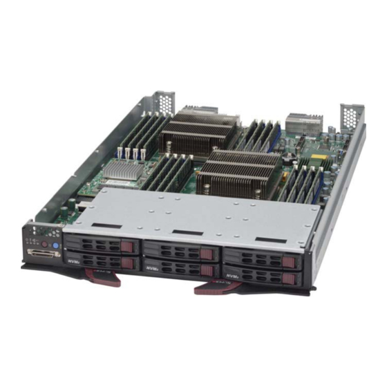
Page 48: Mainboard
SBI-7128R-C6 Blade Module User’s Manual Mainboard The mainboard of the SBI-7128R-C6 blade unit is a proprietary design, which is based on the Intel C612 chipset. See Figure 4-4 for a block diagram of this chipset, Figure 4-3 for a view of the B10DRC mainboard and... - Page 49 Chapter 4: Blade Module Features Table 4-4. B10DRC Mainboard Layout Item Description 2011 CPU1 Socket 2011 CPU2 Socket DIMM Slots (see Figure 3-13: "16-slot DIMM Numbering" on page 3-10 for details) six 2.5" Hot-swap HDD/SSD/NVMe SATA Hard Drive Bays InfiniBand Connectors (for InfiniBand daughter card) Gbx Connectors (for power and logic to backplane) Onboard SATA Port Intel C612 Chipset...
-
Page 50: Jumpers
SBI-7128R-C6 Blade Module User’s Manual Jumpers The jumpers present on the mainboard are used by the manufacturer only; there are no jumpers used to configure the operation of the mainboard. CMOS Clear JBT1 is used to clear CMOS and will also clear any passwords. JBT1 consists of two contact pads located near the BIOS chip. -
Page 51: Blade Unit Components
Chapter 4: Blade Module Features Blade Unit Components Figure 4-5. Exploded View of a SBI-7128R-C6 Blade Module... -
Page 52: Memory Support
Super CAP Memory Support The SBI-7128R-C6 blade module supports up to 512 GB of 32 GB, 16 GB, 8 GB and 4 GB RDIMM or 1 TB of 64 GB and 32 GB LRDIMM, 2133/1866/1600 MHz speed SDRAM memory in sixteen (16) 288-pin DDR4 DIMM sockets. See... -
Page 53: Chapter 5 Raid Setup Procedure
Chapter 5 RAID Setup Procedure Each SBI-7128R-C6 blade module supports up to three hard drives, which may be used to create a RAID 0, 1 and 5 (Windows) or RAID 0, 1 and 10 (Linux) array. For RAID setup use the procedure below. This blade’s BIOS has a RAID utility available in its setup. -
Page 54: Raid Setup Procedure
SBI-7128R-C6 Blade Module User’s Manual RAID Setup Procedure This section provides instructions for configuring arrays and logical drives with the RAID BIOS Configuration Utility. It is recommended that you use drives with the same capacity when you create a storage configurations. If you use drives with different capacities in one array, the configuration utility limits each drive to the capacity of the smallest drive. - Page 55 Chapter 5: RAID Setup Procedure Figure 5-1. BIOS Setup Screen...
-
Page 56: Using The Adaptec Raid Utility
SBI-7128R-C6 Blade Module User’s Manual Using the Adaptec RAID Utility The Adaptec® RAID Utility program is where you can define the drives you want to include in the RAID array and the mode and type of RAID. In the A... -
Page 57: Chapter 6 Bios
NOTE: Due to periodic changes to the BIOS, some settings may have been added or deleted and might not yet be recorded in this manual. Please refer to the http:// www.supermicro.com/products/SuperBlade/module/ web site for further details on BIOS setup and the BIOS menus for your SuperBlade blade module. -
Page 58: Bios Updates
SBI-7128R-C6 Blade Module User’s Manual BIOS Updates It may be necessary to update the BIOS used in the blade modules on occasion. However, it is recommended that you not update BIOS if you are not experiencing problems with a blade module. -
Page 59: Running Setup
Chapter 6: BIOS 3. Go to the V menu and select F IRTUAL EDIA LOPPY MAGE PLOAD 4. B or O to locate the *.img file on your desktop and select it. ROWSE 5. Press the U button and wait a few seconds for the image to upload to the PLOAD CMM. -
Page 60: Main Bios Setup
SBI-7128R-C6 Blade Module User’s Manual Main BIOS Setup Figure 6-1. BIOS Setup Screen All Main Setup options are described in this section. Use the U arrow keys to move among the different settings in each menu. Use the L arrow keys to change the options for each setting. -
Page 61: Advanced Setup
Chapter 6: BIOS Advanced Setup Choose Advanced from the BIOS Setup Utility main menu with the arrow keys to display the A menu. The items with a triangle beside them are DVANCED ETUP sub-menus that can be accessed by highlighting the item and pressing <E >. - Page 62 SBI-7128R-C6 Blade Module User’s Manual Table 6-3. Boot Feature Submenu (Continued) Menu Option Description When enabled, the system will wait for the F1 key to be pressed if an Wait for ‘F1’ If Error error occurs. Options are Enabled or Disabled.
- Page 63 Chapter 6: BIOS Table 6-4. CPU Configuration Submenu (Continued) Menu Option Description For UP platforms, leave this option Enabled. For DP/MP servers, DCU Streamer Prefetcher this option may be used to tune performance to the specific application. Options are Enabled or Disabled. This setting Enables or Disables prefetch of the next L1 line based DCU IP Prefetcher upon sequential load history.
- Page 64 SBI-7128R-C6 Blade Module User’s Manual Table 6-4. CPU Configuration Submenu (Continued) Menu Option Description This setting allows you to Disable or Enable the CPU C3 (ACPI C2) CPU C6 Report report to the OS. It is recommended that this setting be enabled.
- Page 65 Chapter 6: BIOS Table 6-4. CPU Configuration Submenu (Continued) Menu Option Description This sub-menu allows you to configure DRAM RAPL Configuration DRAM RAPL Configuration settings. This setting allows you to enable the DRAM RAPL Baseline and its DRAM RAPL Baseline mode.
- Page 66 SBI-7128R-C6 Blade Module User’s Manual Table 6-5. Chipset Configuration Sub-menu (Continued) Menu Option Description This setting allows you to specify the length of time this port requires PCI-E Port L1 Exit to complete transition from L1 to L0. The options include <1uS, 1uS -...
- Page 67 Chapter 6: BIOS Table 6-5. Chipset Configuration Sub-menu (Continued) Menu Option Description This setting allows you to select the QPI Link Frequency. Options Link Frequency Select include 6.4GB/s, 8.0GB/s, 9.6GB/s, Auto and Auto Limited. Link L0p Enable This setting Enables or Disables Link L0p. Link L1 Enable This setting Enables or Disables Link L1.
- Page 68 SBI-7128R-C6 Blade Module User’s Manual Table 6-5. Chipset Configuration Sub-menu (Continued) Menu Option Description Device Tagging This setting Enables or Disables Device Tagging in your system. South Bridge Configuration This sub-menu allows you to configure South Bridge parameters. Static information for USB Module Version and USB devices USB Information connected is shown at the top of this screen.
- Page 69 Chapter 6: BIOS Table 6-7. sSATA Configuration Sub-menu Menu Option Description sSATA Controller This setting allows you to Enable or Disable the SATA controller. Use this setting to select the SATA mode you desire. Options include IDE, AHCI Configure sSATA as and RAID.
- Page 70 SBI-7128R-C6 Blade Module User’s Manual Table 6-9. PCIe/PCI/PnP Configuration Sub-menu (Continued) Menu Option Description Above 4G Decoding (Available if the Select Enabled to decode a 64-bit PCI device in the space above 4G Address. system supports The options are Enabled and Disabled.
- Page 71 Chapter 6: BIOS Table 6-10. SuperIO Device Configuration Sub-menu Menu Option Description This static display shows the name of the Super IO chip installed for your Super IO Chip system. Serial Port 1/2 This sub-menu allows the user the configure settings of Serial Port 1 or Serial Configuration Port 2.
- Page 72 SBI-7128R-C6 Blade Module User’s Manual Table 6-11. Serial Port Console Redirection Sub-menu (Continued) Menu Option Description A parity bit can be sent along with regular data bits to detect data transmission errors. Select Even if the parity bit is set to 0, and the number of 1's in data bits is even.
-
Page 73: Event Logs Setup
Chapter 6: BIOS Table 6-11. Serial Port Console Redirection Sub-menu (Continued) Menu Option Description This feature allows the user to select the target terminal emulation type for Console Redirection. Select VT100 to use the ASCII character set. Select VT100+ to add color and function key support. Select ANSI to use the extended Terminal Type ASCII character set. - Page 74 SBI-7128R-C6 Blade Module User’s Manual Table 6-14. Event Logs Menu Menu Option Description Change SMBIOS This sub-menu allows you to change the SMBIOS Event Log configuration Event Log Settings settings. Change this setting to enable or disable all features of the SMBIOS SMBIOS Event Event Logging during system boot.
-
Page 75: Ipmi Setup
Chapter 6: BIOS IPMI Setup Choose IPMI Setup from the BIOS Setup main menu with the arrow keys to bring up the IPMI S menu. IPMI setup options are displayed by highlighting the setting using the ETUP arrow keys and pressing <E >. -
Page 76: Security
SBI-7128R-C6 Blade Module User’s Manual Security Choose Security from the BIOS Setup main menu with the arrow keys to bring up the menu. Security setting options are displayed by highlighting the setting ECURITY ETUP using the arrow keys and pressing <E >. -
Page 77: Boot
Chapter 6: BIOS Boot Choose Boot from the 64 MB SPI Flash EEPROM with AMI® BIOS BIOS Setup Utility main menu with the arrow keys to bring up the B menu. Security setting ETUP options are displayed by highlighting the setting using the arrow keys and pressing <E >. -
Page 78: 6-10 Save & Exit
SBI-7128R-C6 Blade Module User’s Manual 6-10 Save & Exit Choose S & E from the 64 MB SPI Flash EEPROM with AMI® BIOS BIOS Setup Utility main menu with the arrow keys to display the S & E menu. All Exit... -
Page 79: Appendix Abios Post Codes
Appendix A BIOS POST Codes BIOS POST Messages During the Power-On Self-Test (POST), the BIOS will check for problems. If a problem is found, the BIOS will activate an alarm or display a message. The following is a list of such BIOS messages. - Page 80 SBI-7428R-C6 Blade Module User’s Manual Table A-1. BIOS POST Messages (Continued) BIOS Message Description Previous POST did not complete successfully. POST loads default values and offers to run Setup. If the failure was caused by incorrect values and they are not corrected, the next boot Previous boot incomplete - Default will likely fail.
-
Page 81: A-2 Bios Post Codes
Appendix A: BIOS POST Codes Table A-1. BIOS POST Messages (Continued) BIOS Message Description Where nnnn is the amount of RAM in kilobytes successfully nnnn kB Extended RAM Passed tested. Where nnnn is the amount of system cache in kilobytes nnnn Cache SRAM Passed successfully tested. -
Page 82: Recoverable Post Errors
SBI-7428R-C6 Blade Module User’s Manual Recoverable POST Errors When a recoverable type of error occurs during POST, the BIOS will display an POST code that describes the problem. BIOS may also issue one of the following beep codes: • One long and two short beeps – video configuration error •... - Page 83 Appendix A: BIOS POST Codes Table A-2. Terminal POST Errors (Continued) Post Code Description 1-3-1-3 Test 8742 Keyboard Controller Auto size DRAM Initialize POST Memory Manager Clear 512 kB base RAM 1-3-4-1 RAM failure on address line xxxx* 1-3-4-3 RAM failure on data bits xxxx* of low byte of memory bus Enable cache before system BIOS shadow Test CPU bus-clock frequency Initialize Phoenix Dispatch Manager...
- Page 84 SBI-7428R-C6 Blade Module User’s Manual Table A-2. Terminal POST Errors (Continued) Post Code Description Test RAM between 512 and 640 kB Test extended memory Test extended memory address lines Jump to UserPatch1 Configure advanced cache registers Initialize Multi Processor APIC Enable external and CPU caches Setup System Management Mode (SMM) area Display external L2 cache size...
- Page 85 Appendix A: BIOS POST Codes Table A-2. Terminal POST Errors (Continued) Post Code Description Build MPTABLE for multi-processor boards Install CD ROM for boot Clear huge ES segment register 1-2 Search for option ROMs. One long, two short beeps on check-sum failure Check for SMART Drive (optional) Shadow option ROMs Set up Power Management...
- Page 86 SBI-7428R-C6 Blade Module User’s Manual Table A-2. Terminal POST Errors (Continued) Post Code Description Initialize system error handler PnPnd dual CMOS (optional) Initialize note dock (optional) Initialize note dock late Force check (optional) Extended checksum (optional) Redirect Int 15h to enable remote keyboard Redirect Int 13h to Memory Technologies Devices such as ROM, RAM, PCMCIA, and serial disk Redirect Int 10h to enable remote serial video...
- Page 87 Appendix A: BIOS POST Codes Table A-3. Boot Block Flash ROM Terminal POST Errors (Continued) Post Code Description Initialize video Initialize System Management Manager Output one beep Clear Huge Segment Boot to Mini DOS Boot to Full DOS If the BIOS detects error 2C, 2E, or 30 (base 512K RAM error), it displays an additional word-bitmap ( ) indicating the address line or bits that failed.
- Page 88 SBI-7428R-C6 Blade Module User’s Manual Notes A-10...
- Page 89 Disclaimer The products sold by Supermicro are not intended for and will not be used in life support systems, medical equipment, nuclear facilities or systems, aircraft, aircraft devices, aircraft/emergency communication devices or other critical systems whose failure to perform be reasonably expected to result in significant injury or loss of life or catastrophic property damage.
- Page 90 SBI-7128R-C6 Blade Module User’s Manual...
Need help?
Do you have a question about the SBI-7128R-C6 and is the answer not in the manual?
Questions and answers