Table of Contents
Advertisement
Quick Links
Advertisement
Table of Contents
Troubleshooting

Subscribe to Our Youtube Channel
Related Manuals for Supermicro SuperBlade SBI-421E-1T3N


Summary of Contents for Supermicro SuperBlade SBI-421E-1T3N
- Page 1 SuperBlade Servers ® SBI-421E-1T3N SBI-421E-5T3N USER’S MANUAL Revision 1.0...
- Page 2 State of California, USA. The State of California, County of Santa Clara shall be the exclusive venue for the resolution of any such disputes. Supermicro's total liability for all claims will not exceed the price paid for the hardware product.
- Page 3 If you have any questions, please contact our support team at: support@supermicro.com This manual may be periodically updated without notice. Please check the Supermicro website for possible updates to the manual revision level. Secure Data Deletion A secure data deletion tool designed to fully erase all data from storage devices can be found on our website: https://www.supermicro.com/about/policies/disclaimer.cfm?url=/wdl/utility/...
-
Page 4: Table Of Contents
Contents Contents Chapter 1 Introduction 1.1 Overview ..........................8 Eligible Enclosures ......................8 1.2 System Features ........................9 Front View ...........................9 Drive Carrier Indicators ....................10 Control Panel .........................11 Top view ..........................12 1.3 Motherboard Layout ......................14 Quick Reference .......................15 Motherboard Block Diagram .....................16 Chapter 2 Installation and Setup 2.1 Unpacking the System .......................17 2.2 Powering Up or Down ......................18 2.3 Installing or Removing the Blade Unit ................19... - Page 5 Contents 2.7 Storage Drives ........................41 Installing Drives .........................41 M.2 Solid State Drives .....................44 Hot-Swap for NVMe Drives ....................46 2.8 System Cooling ........................47 Checking the Server Air Flow ...................47 Overheating ........................47 Checking the Temperature of an NVMe Drive ..............47 2.9 Next Steps ...........................48 Installing the Operating System ..................48 Configuring RAID ......................48 Installing Drivers ........................48...
- Page 6 6.9 Reporting an Issue ......................71 Technical Support Procedures ..................71 Returning Merchandise for Service ...................71 Vendor Support Filing System ..................72 6.10 Feedback .........................72 6.11 Contacting Supermicro ......................73 Appendix A BIOS POST Codes Appendix B Standardized Warning Statements for AC Systems Appendix C Specifications and Compliance...
- Page 7 San Jose, CA 95131 U.S.A. Tel: +1 (408) 503-8000 Fax: +1 (408) 503-8008 Email: marketing@supermicro.com (General Information) Sales-USA@supermicro.com (Sales Inquiries) Government_Sales-USA@supermicro.com (Gov. Sales Inquiries) support@supermicro.com (Technical Support) RMA@supermicro.com (RMA Support) Webmaster@supermicro.com (Webmaster) Website: www.supermicro.com Europe Address: Super Micro Computer B.V.
-
Page 8: Chapter 1 Introduction
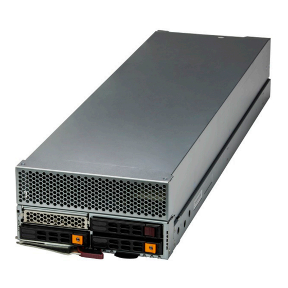
Chapter 1: Introduction Chapter 1 Introduction 1.1 Overview The SBI-421E-xT3N blade is a compact self-contained server that connects into a pre-cabled enclosure that provides power, cooling, management and networking functions. One 8U enclosure can hold up to twenty blades for SBI-421E-1T3N or ten blades for SBI-421E-5T3N. Each blade contains one computing node. -
Page 9: System Features
Chapter 1: Introduction 1.2 System Features Front View AIOM Slot Storage Drive Storage Drive Storage Drive Control Panel Latch Lever Service Tag Figure 1-1. Front View, SBI-421E-1T3N Storage Drive AIOM Slot Storage Drive Storage Drive Control Panel Latch Lever Service Tag Figure 1-2. -
Page 10: Drive Carrier Indicators
Chapter 1: Introduction Drive Carrier Indicators Each drive carrier has two LED indicators: an activity indicator and a status indicator. For RAID configurations using a controller, the meaning of the status indicator is described in the table below. For OS RAID or non-RAID configurations, some LED indications are not supported, such as hot spare. -
Page 11: Control Panel
Chapter 1: Introduction Control Panel System Fail LED KVM/UID LED Power NIC LED Power LED Figure 1-2. Control Panel Control Panel Features Feature State Description The main power switch applies or removes primary power from the power Power button supply to the server but maintains standby power. Green Power on Power LED... -
Page 12: Top View
Chapter 1: Introduction Top view Mezzanine Connector DIMMs Processor and Heatsink DIMMs Processor and Heatsink AIOM Slot Drive Bays Latch Lever Figure 1-3. Components Labeled (SBI-421E-1T3N model shown) - Page 13 Chapter 1: Introduction Blade Components Feature Description Drive Bays Three 2.5" storage drive bays AIOM Slot Position for the optional AIOM Processors and Dual 4th Generation Intel Xeon Scalable processors with heatsinks (SNK-P1046VM (front) Heatsinks and SNK-P1046V (rear)) DIMMs Eight DDR5 memory slots Mezzanine Conn.
-
Page 14: Motherboard Layout
Chapter 1: Introduction 1.3 Motherboard Layout Below is a layout of the B13DET motherboard with jumper, connector and LED locations shown. See the table on the following page for descriptions. For detailed descriptions, pinout information and jumper settings, refer to Chapter 3 or the Motherboard Manual. -
Page 15: Quick Reference
Chapter 1: Introduction Quick Reference Jumper Description Default Setting JBT1 CMOS Clear Open (Normal) Pins 1/2: Normal, Pins 2/3: ME JPME1 ME Recovery Recovery Connector Description Battery (BT1) Onboard battery HDD0/HDD1 Connectors for storage devices (1/2) Power Connector for the storage devices installed on the AOM-SB1-SATA31 HDD2_PWR riser card 3-pin HDD2 SATA 3.0 (3rd SATA Drive) Activity LED header connected to the... -
Page 16: Motherboard Block Diagram
Chapter 1: Introduction B13DET-6 Motherboard Block Diagram CPU1-D1 CPU1-C1 CPU1-B1 CPU1-A1 CPU2-A1 CPU2-B1 CPU2-C1 CPU2-D1 VR14 VR14 8 PHASE 8 PHASE 350W 350W SPR: 16GT EMR: 20GT CPU 1 CPU 2 DDR5 DDR5 PECI: 31 PECI: 30 CPU1-H1 CPU1-G1 CPU1-F1 CPU1-E1 CPU2-E1 CPU2-F1... -
Page 17: Chapter 2 Installation And Setup
Chapter 2: Installation and Setup Chapter 2 Installation and Setup This chapter provides instructions on installing and replacing main system components. To prevent compatibility issues, only use components that match the specifications or part numbers. Up to twenty blade modules may be installed into a blade enclosure, depending upon your enclosure and blade. -
Page 18: Powering Up Or Down
Chapter 2: Installation and Setup 2.2 Powering Up or Down Each blade unit may be powered on and off independently from the rest of the blades in the enclosure. A blade unit may be powered down or up in any of the following ways: •... -
Page 19: Installing Or Removing The Blade Unit
Chapter 2: Installation and Setup 2.3 Installing or Removing a Blade Unit Installing a Blade Unit into the Enclosure 1. Pull the locking lever out and push the blade into its bay. Caution: Insert the blade carefully so the rear connectors are not damaged. 2. -
Page 20: Processor And Heatsink
Chapter 2: Installation and Setup 2.4 Processor and Heatsink Processor Overview The motherboard supports three versions of the 4th Generation Intel Xeon Scalable processors. They differ in the number of cores, and each requires a different CPU carrier. The CPU carriers differ by the presence or absence of shims and levers. SP XCC SP MCC SP HBM... -
Page 21: Installation Overview
(gold contacts). Improper installation or socket misalignment can cause serious damage to the processor or socket, which may require manufacturer repairs. • Refer to the Supermicro website for updates on processor support. Installation Procedure Overview After preparing the system and following ESD precautions, there are four steps to installing the processor and heatsink onto the motherboard. -
Page 22: Create The Processor Carrier Assembly
Chapter 2: Installation and Setup Create the Processor Carrier Assembly Assembling the Process Carrier Assembly 1. Hold the processor with the gold pins (LGA lands) facing down. Locate the gold triangle at the corner of the processor and the corresponding hollowed triangle on the processor carrier as shown below. - Page 23 Chapter 2: Installation and Setup 2. Turn the processor over (with the gold pins up). Locate the CPU keys on the processor and the four latches on the carrier. Latch CPU Key SP XCC Latch CPU Key Latch Latch Latch SP MCC CPU Key Latch...
- Page 24 Chapter 2: Installation and Setup 3. Locate the lever on the processor carrier and press it down (E1A and E1B only). Lever Lever Carrier E1A Carrier E1B 4. Using pin 1 as a guide, carefully align the CPU keys on the processor (A & B) with those on the carrier (a &...
- Page 25 Chapter 2: Installation and Setup 5. Once aligned, carefully insert the CPU into the carrier, making sure that the CPU is secured by latches 1, 2, 3, and 4. Processor Carrier Assembly Processor Carrier Assembly (Top View) (Component Side) SP XCC SP MCC SP HBM...
-
Page 26: Assemble The Processor Heatsink Module
Chapter 2: Installation and Setup Assemble the Processor Heatsink Module Thermal grease is pre-applied on a new heatsink. No additional thermal grease is needed. If this is a re-installation, apply the proper amount of thermal grease to the underside of the heatsink. - Page 27 Chapter 2: Installation and Setup 4. Align "a" on the processor carrier assembly with the triangular cutout "A" on the heatsink along with "b", "c", "d" on the processor assembly with "B", "C", "D" on the heatsink. 5. Once properly aligned, place the heatsink on the processor carrier assembly with all corners matched up, making sure that the four clips are properly securing the heatsink.
-
Page 28: Remove The Socket Cover
Chapter 2: Installation and Setup Remove the Socket Cover Remove the plastic protective cover from the socket by gently squeezing the grip tabs and pulling the cover off. CPU Socket with Plastic Protective Cover... -
Page 29: Install The Phm
Chapter 2: Installation and Setup Install the PHM To install the PHM into the CPU socket, follow these steps. 1. Locate four threaded fasteners (a, b, c, d) and Pin 1 on the CPU socket. (a, b, c, d: Threaded Fasteners) CPU Socket Pin1 2. - Page 30 Chapter 2: Installation and Setup 3. Check the rotating wires (1, 2, 3, 4) to make sure that they are in the unlatched position. Unlatched State Top View Side View Rotating Wire 1 Peek Nut 4. Align PEEK nut "A" (next to the trianglular pin 1 on the heatsink) with threaded fastener "a"...
- Page 31 Chapter 2: Installation and Setup 6. Press all four rotating wires outward and make sure that the heatsink is securely latched into the CPU socket. Latched State 7. With a t30-bit screwdriver, tighten all PEEK nuts in the sequence of "A", "B", "C", and "D"...
-
Page 32: Removing The Phm
Chapter 2: Installation and Setup Removing the PHM To remove the processor heatsink module (PHM) from the motherboard, follow these steps. 1. Shut down the system and unplug the AC power cord from all power supplies. 2. Use a T30-bit screwdriver to loosen the four PEEK nuts on the heatsink in the sequence of A, B, C, and D. - Page 33 Chapter 2: Installation and Setup 4. Gently lift the PHM upward to remove it from the CPU socket.
-
Page 34: Removing The Carrier Assembly From The Heatsink
Chapter 2: Installation and Setup Removing the Carrier Assembly from the Heatsink To remove the processor carrier assembly from the PHM, follow these steps: 1. Detach the four plastic clips (marked a, b, c, d) on the processor carrier assembly from the four corners of the heatsink (marked A, B, C, D) as shown below. -
Page 35: Removing The Processor From The Carrier Assembly
Chapter 2: Installation and Setup Removing the Processor from the Carrier Assembly To remove the processor from the processor carrier, follow these steps. 1. Unlock the lever from its locked position and push it upwards to disengage the processor from the processor carrier as shown below right. Lever 2. -
Page 36: Memory
4800MT/s in 16 DIMM slots. It does not support LRDIMM/LRDIMM- 3DS. For validated memory, use our Product Resources page or the Supermicro product webpage. DDR5 Memory Support for the 4th Generation Intel Xeon Scalable Processors-SP... - Page 37 Chapter 2: Installation and Setup Use the DIMM slots listed below for memory modules. This memory population table is based on guidelines provided by Intel to support Supermicro motherboards. Memory Population, 16 DIMM Slots (X13) CPUs/DIMMs Slots 1 CPU & 1 DIMM A1 or B1 or E1 or F1 1 CPU &...
-
Page 38: Memory Population Guidelines
Balance memory. Using unbalanced memory topology, such as populating two DIMMs in one channel while populating one DIMM in another channel, reduces performance. It is not recommended for Supermicro systems. • In single-CPU configurations, memory must be installed in the DIMM slots associated with the installed CPU. -
Page 39: Installing Memory
Chapter 2: Installation and Setup Installing Memory ESD Precautions Electrostatic Discharge (ESD) can damage electronic com ponents including memory modules. To avoid damaging DIMM modules, it is important to handle them carefully. The following measures are generally sufficient. • Use a grounded wrist strap designed to prevent static discharge. •... -
Page 40: Motherboard Battery
Chapter 2: Installation and Setup 2.6 Motherboard Battery The motherboard uses non-volatile memory to retain system information when system power is removed. This memory is powered by a lithium battery residing on the motherboard. Replacing the Battery Begin by removing power from the system. -
Page 41: Storage Drives
These carriers also help promote proper airflow. Carriers without drives must remain in the chassis for proper airflow. Note: Enterprise level storage drives are recommended for use in Supermicro systems. For information on recommended drives, visit the Supermicro website. - Page 42 Chapter 2: Installation and Setup Removing a Hot-Swap Drive Carrier from the Chassis 1. Press the release button on the drive carrier, which will extend the drive carrier handle. 2. Use the drive carrier handle to pull the drive out of the chassis. Figure 2-5.
- Page 43 Chapter 2: Installation and Setup Installing a Drive 1. Remove the dummy drive, which comes pre-installed in the drive carrier. Pull out the two locking clasps and lift out the dummy drive. Post Post Locking Clasps SB414_25HDD_TRAY_ASSY_REF Figure 2-6. Removing the Dummy Drive from a Carrier 2.
-
Page 44: Solid State Drives
Chapter 2: Installation and Setup M.2 Solid State Drives The motherboard supports one M.2 NVMe solid state drive (SSD) with a length of 80mm. There is a hole in the mounting platform for a plastic clasp to secure the M.2 SSD. M.2 Socket Figure 2-7. - Page 45 Chapter 2: Installation and Setup Installing an M.2 SSD Caution: Use industry-standard anti-static equipment, such as gloves or a wrist strap, and follow precautions to avoid damage caused by ESD. 1. Insert the SSD into the socket on the motherboard or bridge board. Then push it flat against the standoff.
-
Page 46: Hot-Swap For Nvme Drives
Chapter 2: Installation and Setup Hot-Swap for NVMe Drives Supermicro servers support NVMe surprise hot-swap. For even better data security, NVMe orderly hot-swap is recommended. NVMe drives can be ejected and replaced remotely using the BMC Dashboard. Ejecting a Drive 1. -
Page 47: System Cooling
Chapter 2: Installation and Setup 2.8 System Cooling Checking the Server Air Flow • Make sure there are no objects to obstruct airflow in and out of the server. • Do not operate the server without drive carriers in the drive bays. •... -
Page 48: Next Steps
Chapter 2: Installation and Setup 2.9 Next Steps Installing the Operating System Section 4.1 for details. Configuring RAID For RAID setup, see http://www.supermicro.com/support/manuals/ under RAID Installation Guides. Installing Drivers Section 4.2 for details. -
Page 49: Chapter 3 Motherboard Connections
Chapter 3: Motherboard Connections Chapter 3 Motherboard Connections This chapter describes the connections on the motherboard and provides pinout definitions. Note that depending on how the system is configured, not all connections are required. The LEDs on the motherboard are also described here. A motherboard layout indicating component locations may be found in Chapter 1. - Page 50 The JTPM1 header is used to connect a Trusted Platform Module (TPM)/Port 80, which is available from Supermicro. A TPM/Port 80 connector is a security device that supports encryption and authentication in storage drives. It allows the motherboard to deny access if the TPM associated with the storage drive is not installed in the system.
-
Page 51: Control Panel
Chapter 3: Motherboard Connections Control Panel JFP1 contains header pins for the front control panel connections. All JFP1 wires have been bundled into a single cable to simplify this connection. Make sure the red wire plugs into pin 1 as marked on the motherboard. The other end connects to the control panel PCB board. Power Button Reset/UID Button UID LED_N... -
Page 52: Jumpers
Chapter 3: Motherboard Connections Standby Power LED The LED indicator for standby power is pin 8 of JFP1. If this LED is on, standby power is on. RoT (Root of Trust) Power LED The Power LED for RoT (Root of Trust) connection is l pin 9 of JFP1. If this LED is on, power for the RoT chip is on. -
Page 53: Led Indicators
Chapter 3: Motherboard Connections Management Engine (ME) Recovery Use jumper JPME1 to select ME Firmware Recovery mode, which will limit resource allocation for essential system operation only in order to maintain normal power operation and management. In the single operation mode, an online upgrade will be available using Recovery mode. -
Page 54: Chapter 4 Software
An operating system (OS) must be installed on each blade module. Blades with Microsoft Windows OS and blades with Linux OS can operate within the same blade enclosure. Refer to the Supermicro web site for a list of supported operating systems. Installing by using PXE Boot Preboot Execution Environment (PXE) is used to boot a computer over a network. -
Page 55: Driver Installation
The Supermicro website contains drivers and utilities for your system at https://www. supermicro.com/wdl/driver. Some of these must be installed, such as the chipset driver. After accessing the website, go into the CDR_Images (in the parent directory of the above link) and locate the ISO file for your motherboard. Download this file to to a USB flash or media drive. -
Page 56: Superdoctor ® 5
4.3 SuperDoctor ® The Supermicro SuperDoctor 5 is a program that functions in a command-line or web-based interface for Windows and Linux operating systems. The program monitors such system health information as CPU temperature, system voltages, system power consumption, fan speed, and provides alerts via email or Simple Network Management Protocol (SNMP). -
Page 57: Bmc
This can be found on a sticker on the chassis and a sticker on the motherboard. The sticker also displays the BMC MAC address. If necessary, the password can be reset using the Supermicro IPMICFG tool. Figure 4-5. BMC Password Label The sticker can be found on the pull-out service tag at the front of the chassis. -
Page 58: Chapter 5 Optional Components
AOM-B-4M 4x M.2 mezzanine card AIOM Supermicro web page 5.2 TPM Security Module SPI capable TPM 2.0 (or 1.2) with Infineon 9670 controller, horizontal form factor The JTPM1 header is used to connect a Trusted Platform Module (TPM). A TPM is a security device that supports encryption and authentication in hard drives. -
Page 59: Chapter 6 Troubleshooting And Support
Chapter 6 Troubleshooting and Support 6.1 Information Resources Website A great deal of information is available on the Supermicro website, supermicro.com. Figure 6-1. Supermicro Website • Specifications for servers and other hardware are available by clicking the Products option. •... -
Page 60: Bmc Interface
Security Center for recent security notices Supermicro Phone and Addresses 6.2 BMC Interface The system supports a Baseboard Management Controller (BMC) interface. It provides remote access, monitoring and management. There are several BIOS settings related to the BMC. -
Page 61: Troubleshooting Procedures
Chapter 6: Troubleshooting and Support 6.3 Troubleshooting Procedures Use the following procedures to troubleshoot your system. If you have followed all of the procedures below and still need assistance, refer to the Technical Support Procedures Returning Merchandise for Service sections in this chapter. Power down the system before changing any non hot-swap hardware components. -
Page 62: Memory Errors
Also check the Control panel Overheat LED. • Adequate power supply: Make sure that the power supply provides adequate power to the system. Make sure that all power connectors are connected. Refer to the Supermicro website for the minimum power requirements. •... - Page 63 Chapter 6: Troubleshooting and Support If the system becomes unstable before or during OS installation, check the following: • Source of installation: Make sure that the devices used for installation are working properly, including boot devices. • Cable connection: Check to make sure that all cables are connected and working properly. •...
-
Page 64: Crash Dump Using The Bmc Dashboard
In the event of a processor internal error (IERR) that crashes your system, you may want to provide information to support staff. You can download a crash dump of status information using the BMC Dashboard. The BMC manual is available at https://www.supermicro.com/ manuals/other/BMC_Users_Guide_X13.pdf. Check Error Log 1. -
Page 65: Uefi Bios Recovery
Warning: Do not upgrade the BIOS unless your system has a BIOS-related issue. Flashing the wrong BIOS can cause irreparable damage to the system. In no event shall Supermicro be liable for direct, indirect, special, incidental, or consequential damages arising from a BIOS update. - Page 66 USB flash or media drive. Note 1: If you cannot locate the "Super.ROM" file in your drive disk, visit our website at www.supermicro.com to download the BIOS package. Extract the BIOS binary image into a USB flash device and rename it "Super.ROM" for the BIOS recovery use.
- Page 67 Chapter 6: Troubleshooting and Support Note: At this point, you may decide if you want to start the BIOS recovery. If you decide to proceed with BIOS recovery, follow the procedures below. 4. When the screen as shown above displays, use the arrow keys to select the item "Proceed with flash update"...
- Page 68 Chapter 6: Troubleshooting and Support 7. Press <Del> continuously during system boot to enter the BIOS Setup utility. From the top of the tool bar, select Boot to enter the submenu. From the submenu list, select Boot Option #1 as shown below. Then, set Boot Option #1 to [UEFI AP:UEFI: Built-in EFI Shell]. Press <F4>...
- Page 69 Chapter 6: Troubleshooting and Support Note: Do not interrupt this process until the BIOS flashing is complete. 9. The screen above indicates that the BIOS update process is complete. When you see the screen above, unplug the AC power cable from the power supply, clear CMOS, and plug the AC power cable in the power supply again to power on the system.
-
Page 70: Cmos Clear
Chapter 6: Troubleshooting and Support 6.6 CMOS Clear JBT1 is used to clear CMOS, which will also clear any passwords. Instead of pins, this jumper consists of contact pads to prevent accidentally clearing the contents of CMOS. To Clear CMOS 1. -
Page 71: Where To Get Replacement Components
6.8 Where to Get Replacement Components If you need replacement parts for your system, to ensure the highest level of professional service and technical support, purchase exclusively from our Supermicro Authorized Distributors/System Integrators/Resellers. A list can be found at: http://www.supermicro.com. -
Page 72: Vendor Support Filing System
For issues related to Red Hat Enterprise Linux, since it is a subscription based OS, contact your account representative. 6.10 Feedback Supermicro values your feedback as we strive to improve our customer experience in all facets of our business. To provide feedback on our manuals, please email us at techwriterteam@... -
Page 73: Contacting Supermicro
San Jose, CA 95131 U.S.A. Tel: +1 (408) 503-8000 Fax: +1 (408) 503-8008 Email: marketing@supermicro.com (General Information) Sales-USA@supermicro.com (Sales Inquiries) Government_Sales-USA@supermicro.com (Gov. Sales Inquiries) support@supermicro.com (Technical Support) RMA@supermicro.com (RMA Support) Webmaster@supermicro.com (Webmaster) Website: www.supermicro.com Europe Address: Super Micro Computer B.V. -
Page 74: Appendix A Bios Post Codes
Appendix A: BIOS POST Codes Appendix A BIOS POST Codes A.1 BIOS POST Messages During the Power-On Self-Test (POST), the BIOS will check for problems. If a problem is found, the BIOS will activate an alarm or display a message. The following is a list of such BIOS messages. - Page 75 Appendix A: BIOS POST Codes BIOS POST Messages BIOS Message Description Previous POST did not complete successfully. POST loads default values and offers to run Setup. If the failure was caused by incorrect values and Previous boot incomplete - they are not corrected, the next boot will likely fail. On systems with control of Default configuration used wait states, improper Setup settings can also terminate POST and cause this error on the next boot.
- Page 76 Appendix A: BIOS POST Codes BIOS POST Messages BIOS Message Description nnnn kB Extended RAM Where nnnn is the amount of RAM in kilobytes successfully tested. Passed nnnn Cache SRAM Passed Where nnnn is the amount of system cache in kilobytes successfully tested. nnnn kB Shadow RAM Passed Where nnnn is the amount of shadow RAM in kilobytes successfully tested.
- Page 77 Appendix A: BIOS POST Codes One long and two short beeps – video configuration error One repetitive long beep – no memory detected Terminal POST Errors If a terminal type of error occurs, BIOS will shut down the system. Before doing so, BIOS will write the error to port 80h, attempt to initialize video and write the error in the top left corner of the screen.
- Page 78 Appendix A: BIOS POST Codes Terminal POST Errors Code Description 1-3-1-1 Test DRAM refresh 1-3-1-3 Test 8742 Keyboard Controller Auto size DRAM Initialize POST Memory Manager Clear 512 kB base RAM 1-3-4-1 RAM failure on address line xxxx* 1-3-4-3 RAM failure on data bits xxxx* of low byte of memory bus Enable cache before system BIOS shadow Test CPU bus-clock frequency Initialize Phoenix Dispatch Manager...
- Page 79 Appendix A: BIOS POST Codes Terminal POST Errors Code Description Test keyboard Set key click if enabled Enable USB devices 2-2-3-1 Test for unexpected interrupts Initialize POST display service Display prompt “Press F2 to enter SETUP” Disable CPU cache Test RAM between 512 and 640 kB Test extended memory Test extended memory address lines Jump to UserPatch1...
- Page 80 Appendix A: BIOS POST Codes Terminal POST Errors Code Description Detect and install external parallel ports Initialize PC-compatible PnP ISA devices Re-initialize onboard I/O ports. Configure Motherboard Configurable Devices (optional) Initialize BIOS Data Area Enable Non-Maskable Interrupts (NMIs) Initialize Extended BIOS Data Area Test and initialize PS/2 mouse Initialize floppy controller Determine number of ATA drives (optional)
- Page 81 Appendix A: BIOS POST Codes Terminal POST Errors Code Description Clear Boot flag Check for errors Inform RomPilot about the end of POST. POST done - prepare to boot operating system 1 One short beep before boot Terminate QuietBoot (optional) Check password (optional) Initialize ACPI BIOS Prepare Boot...
- Page 82 Appendix A: BIOS POST Codes Terminal POST Errors Code Description Initialize digitizer and display message Unknown interrupt The following are for the boot block in Flash ROM: Boot Block Flash ROM Terminal POST Errors Code Description Initialize the chipset Initialize the bridge Initialize the CPU Initialize system timer Initialize system I/O...
- Page 83 Appendix A: BIOS POST Codes Boot Block Flash ROM Terminal POST Errors Code Description Boot to Full DOS If the BIOS detects error 2C, 2E, or 30 (base 512K RAM error), it displays an additional word- bitmap (xxxx) indicating the address line or bits that failed. For example, “2C 0002” means address line 1 (bit one set) has failed.
-
Page 84: Appendix B Standardized Warning Statements For Ac Systems
Supermicro's Technical Support department for assistance. Only certified technicians should attempt to install or configure components. Read this appendix in its entirety before installing or configuring components in the Supermicro chassis. These warnings may also be found on our website at http://www.supermicro.com/about/... - Page 85 Appendix B: Warning Statements Warnung WICHTIGE SICHERHEITSHINWEISE Dieses Warnsymbol bedeutet Gefahr. Sie befinden sich in einer Situation, die zu Verletzungen führen kann. Machen Sie sich vor der Arbeit mit Geräten mit den Gefahren elektrischer Schaltungen und den üblichen Verfahren zur Vorbeugung vor Unfällen vertraut. Suchen Sie mit der am Ende jeder Warnung angegebenen Anweisungsnummer nach der jeweiligen Übersetzung in den übersetzten Sicherheitshinweisen, die zusammen mit diesem Gerät ausgeliefert wurden.
- Page 86 Appendix B: Warning Statements . ٌ ا ك ً ف حالة و ٌ يك أى تتسبب ف اصابة جسذ ة ٌ هذا الزهز ع ٌ خطز !تحذ ز قبل أى تعول عىل أي هعذات،يك عىل علن بالوخاطز ال ا ٌجوة عي الذوائز ٍ...
- Page 87 Appendix B: Warning Statements Warnung Vor dem Anschließen des Systems an die Stromquelle die Installationsanweisungen lesen. ¡Advertencia! Lea las instrucciones de instalación antes de conectar el sistema a la red de alimentación. Attention Avant de brancher le système sur la source d'alimentation, consulter les directives d'installation. .יש...
- Page 88 Appendix B: Warning Statements Warnung Dieses Produkt ist darauf angewiesen, dass im Gebäude ein Kurzschluss- bzw. Überstromschutz installiert ist. Stellen Sie sicher, dass der Nennwert der Schutzvorrichtung nicht mehr als: 250 V, 20 A beträgt. ¡Advertencia! Este equipo utiliza el sistema de protección contra cortocircuitos (o sobrecorrientes) del edificio.
- Page 89 Appendix B: Warning Statements Power Disconnection Warning Warning! The system must be disconnected from all sources of power and the power cord removed from the power supply module(s) before accessing the chassis interior to install or remove system components. 電源切断の警告 システムコンポーネントの取り付けまたは取り外しのために、...
- Page 90 Appendix B: Warning Statements אזהרה מפני ניתוק חשמלי !אזהרה יש לנתק את המערכת מכל מקורות החשמל ויש להסיר את כבל החשמלי מהספק .לפני גישה לחלק הפנימי של המארז לצורך התקנת או הסרת רכיבים يجب فصم اننظاو من جميع مصادر انطاقت وإ ز انت سهك انكهرباء من وحدة امداد انطاقت...
- Page 91 Appendix B: Warning Statements ¡Advertencia! Solamente el personal calificado debe instalar, reemplazar o utilizar este equipo. Attention Il est vivement recommandé de confier l'installation, le remplacement et la maintenance de ces équipements à des personnels qualifiés et expérimentés. !אזהרה .צוות מוסמך בלבד רשאי להתקין, להחליף את הציוד או לתת שירות עבור הציוד واملدربيه...
- Page 92 Appendix B: Warning Statements Warnung Diese Einheit ist zur Installation in Bereichen mit beschränktem Zutritt vorgesehen. Der Zutritt zu derartigen Bereichen ist nur mit einem Spezialwerkzeug, Schloss und Schlüssel oder einer sonstigen Sicherheitsvorkehrung möglich. ¡Advertencia! Esta unidad ha sido diseñada para instalación en áreas de acceso restringido. Sólo puede obtenerse acceso a una de estas áreas mediante la utilización de una herramienta especial, cerradura con llave u otro medio de seguridad.
- Page 93 Appendix B: Warning Statements Battery Handling Warning! There is the danger of explosion if the battery is replaced incorrectly. Replace the battery only with the same or equivalent type recommended by the manufacturer. Dispose of used batteries according to the manufacturer's instructions 電池の取り扱い...
- Page 94 Appendix B: Warning Statements هناك خطر من انفجار يف حالة اسحبذال البطارية بطريقة غري صحيحة فعليل اسحبذال البطارية فقط بنفس النىع أو ما يعادلها مام أوصث به الرشمة املصنعة جخلص من البطاريات املسحعملة وفقا لحعليامت الرشمة الصانعة 경고! 배터리가 올바르게 교체되지 않으면 폭발의 위험이 있습니다. 기존 배터리와 동일하거나 제 조사에서...
- Page 95 Appendix B: Warning Statements ¡Advertencia! Puede que esta unidad tenga más de una conexión para fuentes de alimentación. Para cortar por completo el suministro de energía, deben desconectarse todas las conexiones. Attention Cette unité peut avoir plus d'une connexion d'alimentation. Pour supprimer toute tension et tout courant électrique de l'unité, toutes les connexions d'alimentation doivent être débranchées.
- Page 96 Appendix B: Warning Statements Backplane Voltage Warning! Hazardous voltage or energy is present on the backplane when the system is operating. Use caution when servicing. バックプレーンの電圧 システムの稼働中は危険な電圧または電力が、 バックプレーン上にかかっています。 修理する際には注意く ださい。 警告 当系统正在进行时,背板上有很危险的电压或能量,进行维修时务必小心。 警告 當系統正在進行時,背板上有危險的電壓或能量,進行維修時務必小心。 Warnung Wenn das System in Betrieb ist, treten auf der Rückwandplatine gefährliche Spannungen oder Energien auf.
- Page 97 Appendix B: Warning Statements هناك خطز مه التيار الكهزبايئ أوالطاقة املىجىدة عىل اللىحة عندما يكىن النظام يعمل كه حذ ر ا عند خدمة هذا الجهاس 경고! 시스템이 동작 중일 때 후면판 (Backplane)에는 위험한 전압이나 에너지가 발생 합니다. 서비스 작업 시 주의하십시오. Waarschuwing Een gevaarlijke spanning of energie is aanwezig op de backplane wanneer het systeem in gebruik is.
- Page 98 Appendix B: Warning Statements תיאום חוקי החשמל הארצי !אזהרה .התקנת הציוד חייבת להיות תואמת לחוקי החשמל המקומיים והארציים تركيب املعدات الكهربائية يجب أن ميتثل للقىاويه املحلية والىطىية املتعلقة بالكهرباء 경고! 현 지역 및 국가의 전기 규정에 따라 장비를 설치해야 합니다. Waarschuwing Bij installatie van de apparatuur moet worden voldaan aan de lokale en nationale elektriciteitsvoorschriften.
- Page 99 Appendix B: Warning Statements Attention La mise au rebut ou le recyclage de ce produit sont généralement soumis à des lois et/ou directives de respect de l'environnement. Renseignez-vous auprès de l'organisme compétent. סילוק המוצר !אזהרה .סילוק סופי של מוצר זה חייב להיות בהתאם להנחיות וחוקי המדינה التخلص...
- Page 100 Appendix B: Warning Statements Warnung Gefährlich Bewegende Teile. Von den bewegenden Lüfterblätter fern halten. Die Lüfter drehen sich u. U. noch, wenn die Lüfterbaugruppe aus dem Chassis genommen wird. Halten Sie Finger, Schraubendreher und andere Gegenstände von den Öffnungen des Lüftergehäuses entfernt.
- Page 101 Verbindungskabeln, Stromkabeln und/oder Adapater, die Ihre örtlichen Sicherheitsstandards einhalten. Der Gebrauch von anderen Kabeln und Adapter können Fehlfunktionen oder Feuer verursachen. Die Richtlinien untersagen das Nutzen von UL oder CAS zertifizierten Kabeln (mit UL/CSA gekennzeichnet), an Geräten oder Produkten die nicht mit Supermicro gekennzeichnet sind.
- Page 102 .قيرح وأ لطع يف ببستي دق ىرخأ تالوحمو تالباك يأ مادختسا .ميلسلا سباقلاو لصوملا مجح لبق نم ةدمتعملا تالباكلا مادختسا تادعملاو ةيئابرهكلا ةزهجألل ةمالسلا نوناق رظحيUL وأCSA ( ةمالع لمحت يتلاوUL/CSA) لبق نم ةددحملاو ةينعملا تاجتنملا ريغ ىرخأ تادعم يأ عمSupermicro.
- Page 103 사항을 준수하여 제공되거나 지정된 연결 혹은 구매 케이블, 전원 케이블 및 AC 어댑터를 사용하십시오. 다른 케이블이나 어댑터를 사용하면 오작동이나 화재가 발생할 수 있습니다. 전기 용품 안전법은 UL 또는 CSA 인증 케이블 (코드에 UL / CSA가 표시된 케이블)을 Supermicro 가 지정한 제품 이외의 전기 장치에 사용하는 것을 금지합니다. Stroomkabel en AC-Adapter...
-
Page 104: Appendix C Specifications And Compliance
Appendix C: System Specifications Appendix C Specifications and Compliance Processors Dual 4th Generation Intel Xeon Scalable processors in socket E1 (LGA4677) with three UPIs (16GT/s max.); the TDP (Thermal Design Power) maximum varies with the model: SBI-421E-1T3N TDP up to 205W (air cooling) or 350W (liquid cooling) SBI-421E-5T3N TDP up to 350W (air cooling) Chipset Intel C741... - Page 105 Appendix C: System Specifications Regulatory Compliance FCC, ICES, CE, VCCI, RCM, UKCA, NRTL, CB Applied Directives, Standards EMC/EMI: 2014/30/EU (EMC Directive) Electromagnetic Compatibility Regulations 2016 FCC Part 15 ICES-003 VCCI-CISPR 32 AS/NZS CISPR 32 BS/EN55032 BS/EN55035 CISPR 32 CISPR 35 BS/EN 61000-3-2 BS/EN 61000-3-3 BS/EN 61000-4-2...
- Page 106 Appendix C: System Specifications General Data Center Environmental Specifications Particulate contamination specifications Air filtration: Data centers must be kept clean to Class 8 of ISO 14644-1 (ISO 2015). The air entering the data center should be filtered with a MERV 11 filter or better. The air within the data center should be continuously filtered with a MERV 8 filter or better.
Need help?
Do you have a question about the SuperBlade SBI-421E-1T3N and is the answer not in the manual?
Questions and answers