Table of Contents
Advertisement
Quick Links
Download this manual
See also:
Quick Manual
Advertisement
Table of Contents

Related Manuals for VIA Technologies ARTiGO A1250


Summary of Contents for VIA Technologies ARTiGO A1250
- Page 1 USER MANUAL ARTiGO A1250 Ultra-slim system for semi-embedded industrial application for digital signage media player 1.04-05032017-094900...
- Page 2 VIA Technologies, Inc. reserves the right the make changes to the products described in this manual at any time without prior notice. Regulatory Compliance FCC-A Radio Frequency Interference Statement This equipment has been tested and found to comply with the limits for a class A digital device, pursuant to part 15 of the FCC rules.
-
Page 3: Safety Precautions
Battery Recycling and Disposal Only use the appropriate battery specified for this product. Do not re-use, recharge, or reheat an old battery. Do not attempt to force open the battery. Do not discard used batteries with regular trash. Discard used batteries according to local regulations. CAUTION RISK OF EXPLOSION IF BATTERY IS REPLACED BY AN INCORRECT TYPE. -
Page 4: Box Contents
ARTiGO A1250 User Manual Box Contents 1 x ARTiGO A1250 system 1 x AC-to-DC adapter 1 x Power cord 1 x SATA cable 1 x Screw pack for HDD 1 x DC plug strap holder Ordering Information Part Number Description ®... -
Page 5: Table Of Contents
ARTiGO A1250 User Manual Table of Contents 1. Product Overview ........................1 1.1. Key Features ................................ 1 ® 1.1.1. Powered by VIA Eden X4 Processor ...................... 1 1.1.2. Compact, Ultra-slim and Space Saving ....................1 1.1.3. Optimize Integration with Dual Sided I/O Access ................1 1.1.4. - Page 6 ARTiGO A1250 User Manual 4.5.7.2. EuP/ErP Lot6 support ........................29 4.5.7.3. S5 Wakeup On LAN........................29 4.5.7.4. Eup/Erp Lot6 Support ........................29 4.6. Chipset Settings ...............................30 4.6.1. DRAM Configuration ..........................31 4.6.1.1. DRAM Clock ........................... 31 4.6.1.2. VGA Share Memory (Frame Buffer) ................... 32 4.6.2.
- Page 7 Figure 1: Front panel I/O layout ............................5 Figure 2: Back panel I/O layout ............................5 Figure 3: Dimensions of the ARTiGO A1250 (front view) ..................6 Figure 4: Dimensions of the ARTiGO A1250 (side view) ...................6 Figure 5: Dimensions of the ARTiGO A1250 (bottom view) ..................6 Figure 6: Power on/off button diagram ...........................7...
- Page 8 ARTiGO A1250 User Manual Lists of Tables Table 1: USB 2.0 port pinout .............................7 Table 2: Audio jack receptacle description ........................8 Table 3: DC-in jack pinout ..............................8 Table 4: Gigabit Ethernet port pinout ..........................9 Table 5: Gigabit Ethernet port LED color definition ....................9 Table 6: USB 3.0 port pinout ............................
-
Page 9: Product Overview
1.1.2. Compact, Ultra-slim and Space Saving The ARTiGO A1250 has an ultra slim and compact chassis, designed to save space that makes it suitable to install in space critical environment and to ensure maximum reliability. It is using a low noise but high efficient fan as a thermal solution. -
Page 10: Product Specifications
ARTiGO A1250 User Manual 1.2. Product Specifications Processor Core Logic System ® 1.2GHz VIA Eden Chipset VIA VX11H Media System Processor 1066/1333 MHz FSB support System Memory 1 x SODIMM slot supporting DDR3 1066/1333 MHz Up to 8GB memory size... - Page 11 ARTiGO A1250 User Manual Serial Supports two USB 2.0 ports Supports two USB 3.0 ports Storage Interface Signal Interface 1 x onboard SATA II connector, maximum data transfer rate up to 300MB/s 1 x onboard SATA power connector ...
- Page 12 1. The ambient temperature and the CPU loadings affect the system fan rpm. Therefore, the higher rpm will generate higher fan noise (dB). The smart fan of ARTiGO A1250 system runs at lowest speed (default) at 25°C room temperature and when the CPU loading is less than 60%.
-
Page 13: Layout Diagram
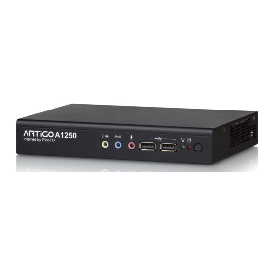
ARTiGO A1250 User Manual 1.3. Layout Diagram USB 2.0 Power On/Off A1250 Inspired by Pico-ITX Line-out Mic-in HDD LED Line-in Power LED Figure 1: Front panel I/O layout Gigabit Ethernet Wi-Fi antenna hole DC-in Mini HDMI +12V HDMI DC plug strap holder hole USB 3.0... -
Page 14: Dimensions
ARTiGO A1250 User Manual 1.4. Dimensions Figure 3: Dimensions of the ARTiGO A1250 (front view) Figure 4: Dimensions of the ARTiGO A1250 (side view) 1 0 0 Figure 5: Dimensions of the ARTiGO A1250 (bottom view) -
Page 15: External I/O Pin Descriptions And Functionality
ARTiGO A1250 User Manual 2. External I/O Pin Descriptions and Functionality The VIA ARTiGO A1250 has a wide selection of interfaces located on the front and back panels as part of the external I/O. 2.1. Power On/Off Button The ARTiGO-1250 comes with a Power on/off button that supports Soft Power-On/Off (Instant Off or 4 second delay) and Suspend. -
Page 16: Audio Jack
TRS jack, 3.5mm Ø 5P, 90 Degree, Female, shielded Table 2: Audio jack receptacle description 2.5. DC-in Jack The ARTiGO A1250 comes with a DC power input jack on the back panel that carries 12V DC. external power input. +12V... -
Page 17: Gigabit Ethernet Port
ARTiGO A1250 User Manual 2.6. Gigabit Ethernet Port The ARTiGO A1250 system is equipped with one Gigabit Ethernet port on the back panel. The Gigabit Ethernet port is fully compliant with IEEE 802.3 (10BASE-T), 802.3u (100BASE-TX), and 802.3ab (1000BASE-T) standards. The pinout of the Gigabit Ethernet port is shown below... -
Page 18: Usb 3.0 Port
Table 6: USB 3.0 port pinout 2.8. VGA Port The ARTiGO A1250 provides a high resolution VGA interface through a 15-pin D-sub female connector to support analog VGA monitors. It supports up to 2560 x 1600 @ 60Hz resolution and up to 512MB shared memory. -
Page 19: Mini Hdmi Port
ARTiGO A1250 User Manual ® 2.9. Mini HDMI Port ® ® ® The integrated 19-pin mini HDMI port uses an HDMI Type C connector as defined in the HDMI ® ® ® specification. The mini HDMI port is for connecting to HDMI displays. -
Page 20: Hardware Installation
3.1. Installing the DDR3 SODIMM memory Step 1 On the bottom side of the ARTiGO A1250, remove the two screws from the memory access cover. Then gently lift up the cover. Figure 15: Removing the memory access cover Step 2 Align the notch on the SODIMM memory module with the protruding wedge on the SODIMM slot. -
Page 21: Figure 17: Removing The Memory Thermal Pad Protective Cover
ARTiGO A1250 User Manual Step 3 Flip over the memory access cover and remove the protective plastic cover of the pre-installed memory thermal pad. Figure 17: Removing the memory thermal pad protective cover Step 4 Reinstall the memory access cover and secure it with two screws. -
Page 22: Removing The Ddr3 Sodimm Memory
ARTiGO A1250 User Manual 3.2. Removing the DDR3 SODIMM Memory Step 1 To disengage the locking clips, push the locking clips horizontally outward away from the SODIMM memory module. Figure 19: Disengaging the SODIMM locking clips Step 2 When the locking clips have cleared, the SODIMM memory module will automatically pop up to the 30 degrees angle, next remove the memory module. -
Page 23: Installing 2.5" Sata Hard Disk Drive
ARTiGO A1250 User Manual 3.3. Installing 2.5” SATA Hard Disk Drive Step 1 Remove the six screws of the top cover from both sides and bottom side of the chassis. Slightly pull the cover horizontally then gently pull up the cover. -
Page 24: Figure 23: Removing The Hard Disk Thermal Pad Protective Cover
ARTiGO A1250 User Manual Step 3 Pull out the hard disk bracket tray. Then remove the cover plastic of the hard disk thermal pad. Figure 23: Removing the hard disk thermal pad protective cover Step 4 Flip over the hard disk drive and install it to the hard disk bracket tray over the thermal pad. Make sure the plastic cover of the thermal pad has been removed before installing the hard disk. -
Page 25: Figure 25: Reinstalling The Hard Disk Drive Tray
ARTiGO A1250 User Manual Step 5 Gently slide back the bracket tray with the 2.5” hard disk. Ensure that no wiring will be trapped while reinstalling the bracket tray. Secure the bracket tray with screw. Figure 25: Reinstalling the hard disk drive tray Step 6 Connect the SATA cable (power and data) to the hard disk drive. -
Page 26: Installing The Rubber Feet
ARTiGO A1250 User Manual 3.4. Installing the Rubber Feet Step 1 Locate the area where to install the rubber feet. Step 2 Attach carefully each rubber foot. Firmly press it down to ensure the rubber foot is properly in place. -
Page 27: Installing The Dc Plug Strap Holder
ARTiGO A1250 User Manual 3.5. Installing the DC Plug Strap Holder Step 1 Prepare the DC plug strap holder. The DC plug strap holder consists of two parts: Slide strap tie and Plug holder. slide rails Locking clip Slide strap tie... -
Page 28: Figure 31: Installing The Plug Holder
ARTiGO A1250 User Manual Step 4 Attach the plug holder to the DC plug cable. Figure 31: Installing the plug holder Step 5 Insert the slide strap tie into the side of the plug holder. Figure 32: Inserting the slide strap tie Step 6 Slide in the plug holder deeply until the DC plug reaches the DC-in jack. -
Page 29: Bios Setup Utility
ARTiGO A1250 User Manual 4. BIOS Setup Utility 4.1. Entering the BIOS Setup Utility Power on the computer and press Delete during the beginning of the boot sequence to enter the BIOS Setup Utility. If the entry point has passed, restart the system and try again. -
Page 30: System Overview
ARTiGO A1250 User Manual 4.4. System Overview The System Overview screen is the default screen that is shown when the BIOS Setup Utility is launched. This screen can be accessed by traversing the navigation bar to the “Main” label. Figure 34: Illustration of the Main menu screen 4.4.1. -
Page 31: Advanced Settings
ARTiGO A1250 User Manual 4.5. Advanced Settings The Advanced Settings screen shows a list of categories that can provide access to a sub-screen. Sub- screen links can be identified by the preceding right-facing arrowhead. Figure 35: Illustration of the Advanced Settings screen... -
Page 32: Acpi Settings
ARTiGO A1250 User Manual 4.5.1. ACPI Settings ACPI grants the operating system direct control over system power management. The ACPI Configuration screen can be used to set a number of power management related functions. Figure 36: Illustration of the ACPI Settings screen 4.5.1.1. -
Page 33: S5 Rtc Wake Settings
ARTiGO A1250 User Manual 4.5.2. S5 RTC Wake Settings Figure 37: Illustration of the S5 RTC Wake Settings screen 4.5.2.1. Wake system with Fixed Time Enable or disable system wake on alarm event. When enabled, system will wake on the hr:min:sec specified. -
Page 34: Cpu Configuration
ARTiGO A1250 User Manual 4.5.3. CPU Configuration The CPU Configuration screen shows detailed information about the built-in processor. In addition to the processor information, the thermal controls can be set. Figure 38: Illustration of CPU Configuration screen 4.5.3.1. TM3 The TM3 Function has two settings: Disabled and Enabled. When the setting is changed to “Disabled”, the CPU’s built-in thermal sensor will not function. -
Page 35: Sata Configuration
ARTiGO A1250 User Manual 4.5.4. SATA Configuration The SATA Configuration screen allows the user to view and configure the settings of the SATA configuration settings. Figure 39: Illustration of SATA Configuration screen 4.5.4.1. SATA Mode This option allows the user to manually configure SATA controller for a particular mode. -
Page 36: Pc Health Status
ARTiGO A1250 User Manual 4.5.5. PC Health Status The PC Health Status screen has no editable fields. The system temperature is taken from an optional sensor that is connected to the J5 pin header. Figure 40: Illustration of PC Health Status screen 4.5.6. -
Page 37: Onboard Device Configuration
ARTiGO A1250 User Manual 4.5.7. OnBoard Device Configuration The OnBoard Device Configuration screen has the following features. Figure 42: Illustration of OnBoard Device Configuration screen 4.5.7.1. OnBoard LAN Enable The OnBoard LAN Enable feature determines whether the onboard LAN controller will be used or not. -
Page 38: Chipset Settings
ARTiGO A1250 User Manual 4.6. Chipset Settings The Chipset Settings screen shows a list of categories that can provide access to a sub-screen. Sub-screen links can be identified by the preceding right-facing arrowhead. Figure 43: Illustration of Chipset Settings screen... -
Page 39: Dram Configuration
ARTiGO A1250 User Manual 4.6.1. DRAM Configuration The DRAM Configuration screen has two features for controlling the system DRAM. All other DRAM features are automated and cannot be accessed. Figure 44: Illustration of DRAM Configuration screen 4.6.1.1. DRAM Clock The DRAM Clock option enables the user to determine how the BIOS handles the memory clock frequency. -
Page 40: Vga Share Memory (Frame Buffer)
ARTiGO A1250 User Manual 4.6.1.2. VGA Share Memory (Frame Buffer) The VGA Share Memory feature enables the user to choose the amount of the system memory to reserve for use by the integrated graphics controller. The selections of memory amount that can be reserved are 256MB, 512MB and 1024MB. -
Page 41: Pmu_Acpi Configuration
ARTiGO A1250 User Manual 4.6.3. PMU_ACPI Configuration The PMU_ACPI Configuration screen can be used to set a number of power management related functions. Figure 46: Illustration of PMU_ACPI Configuration screen 4.6.3.1. Other Control Figure 47: Illustration of Other Control screen... -
Page 42: Ac Loss Auto-Restart
ARTiGO A1250 User Manual 4.6.3.1.1. AC Loss Auto-restart AC Loss Auto-restart defines how the system will respond after AC power has been interrupted while the system is on. There are three options. Power Off The Power Off option keeps the system in an off state until the power button is pressed again. -
Page 43: Boot Settings
ARTiGO A1250 User Manual 4.7. Boot Settings The Boot Settings screen has a single link that goes to the Boot Configuration and Boot Option Priorities screens. Figure 49: Illustration of Boot Settings screen 4.7.1. Boot Configuration The Boot Settings Configuration screen has several features that can be run during the system boot sequence. -
Page 44: Save & Exit
ARTiGO A1250 User Manual 4.8. Save & Exit The Save & Exit Configuration screen has the following features: Figure 50: Illustration of Save & Exit screen 4.8.1. Save Changes and Exit Save all changes to the BIOS and exit the BIOS Setup Utility. The “F4” hotkey can also be used to trigger this command. -
Page 45: Driver Installation
ARTiGO A1250 User Manual 5. Driver Installation 5.1. Microsoft Driver Support The ARTiGO A1250 is compatible with Microsoft operating systems. The latest Windows drivers can be downloaded from the VIA website at http://www.viatech.com For embedded operating systems, the related drivers can be found in the VIA website at http://www.viatech.com... -
Page 46: Appendix A. Installing Wireless Accessories
ARTiGO A1250 User Manual Appendix A. Installing Wireless Accessories This section provides information on how to install the wireless accessories to provide Wi-Fi connection. A.1. Installing the VNT9721 USB Wi-Fi Dongle Step 1 Locate a USB 2.0 or USB 3.0 port on the panel I/O. -
Page 47: Installing The Emio-1533 Usb Wi-Fi Module
ARTiGO A1250 User Manual A.2. Installing the EMIO-1533 USB Wi-Fi Module Step 1 Mount the EMIO-1533 module on the P910-C daughterboard. Align the module’s mounting holes with the standoff screw hole then secure it with two screws. Figure 52: Installing EMIO-1533 module Step 2 Remove the P910-D bridge board connector. -
Page 48: Figure 54: Connecting Usb Wi-Fi Cable And Reinstalling The P910-D Bridge Board Connector
ARTiGO A1250 User Manual Step 3 Connect one end of the USB Wi-Fi cable to the EMIO-1533 module, and then connect the other end of the cable to the P910-C daughterboard. The USB Wi-Fi cable must be laid out underneath the P910-D bridge board connector. -
Page 49: Figure 56: Installing The Wi-Fi Antenna
ARTiGO A1250 User Manual Step 5 Insert the Wi-Fi antenna cable into the antenna hole from the inside of the chassis. Insert the washer, fasten it with the nut and install the external antenna. Connect the other end of the Wi-Fi antenna cable to the micro-RF connector labeled “IPEX”...
Need help?
Do you have a question about the ARTiGO A1250 and is the answer not in the manual?
Questions and answers