VIA Technologies ARTiGO A900 User Manual
Fanless ultra-compact android system
Hide thumbs
Also See for ARTiGO A900:
- User manual (39 pages) ,
- Development manual (43 pages) ,
- Evaluation manual (33 pages)
Table of Contents
Advertisement
Quick Links
Advertisement
Table of Contents

Related Manuals for VIA Technologies ARTiGO A900


Summary of Contents for VIA Technologies ARTiGO A900
- Page 1 USER MANUAL ARTiGO A900 Fanless ultra-compact Android system 1.13-05182018-114100...
- Page 2 VIA Technologies, Inc. reserves the right the make changes to the products described in this manual at any time without prior notice. Regulatory Compliance FCC-A Radio Frequency Interference Statement This equipment has been tested and found to comply with the limits for a class A digital device, pursuant to part 15 of the FCC rules.
- Page 3 Battery Recycling and Disposal Only use the appropriate battery specified for this product. Do not re-use, recharge, or reheat an old battery. Do not attempt to force open the battery. Do not discard used batteries with regular trash. Discard used batteries according to local regulations. Safety Precautions Always read the safety instructions carefully.
- Page 4 Optional Accessories Wireless Modules Part Number Description 00GO27100BU2B0D0 VNT9271BU0DB IEEE 802.11 b/g/n USB Wi-Fi dongle EMIO-2550-00A1 3.75G HSPA/UMTS mobile broadband full size miniPCIe module with GPS and SIM card slot (Note: GPS function is not currently supported for ARTiGO A900)
-
Page 5: Table Of Contents
ARTiGO A900 User Manual Table of Contents 1. Product Overview ........................1 1.1. Key Features ............................1 1.1.1. ARM Based System ............................. 1 1.1.2. Ultra Compact, Slim Size and Space Saving ..................1 1.1.3. Optimize Integration with Multiple I/O Access ................... 1 1.1.4. - Page 6 ARTiGO A900 User Manual 5.4. Connecting Console cable ......................30 5.5. Installing the VESA mounting kit (optional) ................31 5.6. Connecting the COM and DIO cables ..................34 6. Software and Technical Supports ................... 35 6.1. Android Support..........................35 6.1.1.
- Page 7 Figure 36: Connecting Console cable .......................... 30 Figure 37: Installing the VESA bracket ......................... 31 Figure 38: Installing the VESA plate ..........................32 Figure 39: Installing ARTiGO A900 system to the VESA plate ................33 Figure 40: Connecting the COM and DIO cables ...................... 34...
- Page 8 ARTiGO A900 User Manual List of Tables Table 1: Audio jack description ............................9 Table 2: USB 2.0 ports pinout ............................10 Table 3: Gigabit Ethernet port pinout .......................... 10 Table 4: Gigabit Ethernet port LED color definition ....................11 Table 5: Mini HDMI-out port pinout..........................11 Table 6: Mini USB 2.0 port pinout ..........................
-
Page 9: Product Overview
1.1.2. Ultra Compact, Slim Size and Space Saving The ARTiGO A900 has an ultra slim and compact chassis, designed to save space that makes it suitable to install in space critical environment and to ensure maximum reliability. Its chassis design has a robust aluminum alloy top cover and steel bottom chassis. -
Page 10: Mounting Solution
ARTiGO A900 User Manual 1.1.7. Mounting Solution ARTiGO A900 supports multiple methods for mounting. It can be mounted to VESA mountable surfaces or even to wall with the VESA mounting kit (optional). 1.1.8. Embedded OS Ready The ARTiGO A900 is compatible with Android 4.4.2 operating system. -
Page 11: Product Specifications
ARTiGO A900 User Manual 1.2. Product Specifications Processor o 1.0GHz VIA Elite E1000 Cortex-A9 dual-core SoC System Memory o 2GB DDR3 SDRAM onboard Storage o 4GB eMMC Flash memory o Supports one mSATA slot Graphics o Three integrated, independent 3D/2D and video processing units ®... - Page 12 ARTiGO A900 User Manual o 1 x Power on/off button with built-in LED o 1 x Red LED indicator for mSATA status o 2 x Audio jacks: Line-out and Mic-in o 3 x USB 2.0 ports Back Panel I/O o 1 x 8-pin COM connector (RS-232/485)
- Page 13 ARTiGO A900 User Manual Software Compatibility (Operating System) o Android 4.4.2 Note: As the operating temperature provided in the specifications is a result of the test performed in VIA’s chamber, a number of variables can influence this result. Please note that the working temperature may vary depending on the actual situation and environment.
-
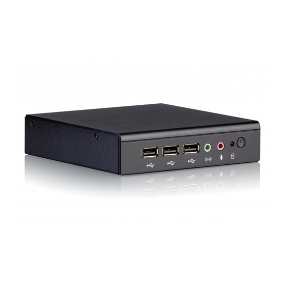
Page 14: Panel Layout
ARTiGO A900 User Manual 1.3. Panel Layout Figure 1: Front panel I/O layout Figure 2: Back panel I/O layout... -
Page 15: Dimensions
ARTiGO A900 User Manual 1.4. Dimensions Figure 3: Front side view dimensions Figure 4: Right side view dimension Figure 5: Bottom side view dimensions... -
Page 16: External I/O Pin Descriptions And Functionality
Figure 6: Power on/off button diagram 2.2. LED Indicator There is one LED on the front panel of the ARTiGO A900 that indicates the status of the system: • mSATA LED flashes in red and indicates the mSATA storage activity. -
Page 17: Table 1: Audio Jack Description
ARTiGO A900 User Manual Jack Description Line-out TRS jack, 3.5mm Ø 5P, 90 Degree, Female, shielded Mic-in TRS jack, 3.5mm Ø 5P, 90 Degree, Female, shielded Table 1: Audio jack description... -
Page 18: Usb 2.0 Port
2.4. USB 2.0 Port The ARTiGO A900 is equipped with three USB 2.0 ports on the front panel. Each USB port gives complete Plug and Play and hot swap capability for external devices. The USB interface complies with USB UHCI, Rev. -
Page 19: Mini Hdmi-Out Port
2.6. Mini HDMI-Out Port ® The ARTiGO A900 is equipped with mini HDMI-out port (19-pin HDMI Type C connector) located on the back panel. The HDMI-out port is used to connect high definition video and digital audio using a single cable. -
Page 20: Figure 12: Mini Usb 2.0 Port Diagram
ARTiGO A900 User Manual The ARTiGO A900 has a Mini USB 2.0 port located on the back panel. The Mini USB 2.0 interface port gives complete Plug and Play and hot swap capability for external devices and it complies with USB UHCI, rev. 2.0. -
Page 21: Micro Sd Card Slot
ARTiGO A900 User Manual 2.8. Micro SD Card Slot The ARTiGO A900 comes with a Micro SD card slot located on the back panel. The Micro SD card slot enables storage of Micro SD card memory up to 32GB capacity. -
Page 22: Com Connector
Table 9: COM connector pinout 2.11. DC-In Jack The ARTiGO A900 comes with a DC power input jack on the back panel that carries +12V DC external power input. The pinout of the DC-in jack is shown below. Figure 16: DC-in jack diagram... -
Page 23: Onboard I/O
This chapter provides information about the onboard slots and pin header. 3.1. mSATA Slot The ARTiGO A900 comes with mSATA slot to support mSATA flash drive module to have flexible storage. The mSATA slot is labeled as “MSATA”. The location of the mSATA slot is shown below. -
Page 24: Console Debug Pin Header
ARTiGO A900 User Manual 3.3. Console Debug Pin Header The ARTiGO A900 is equipped with Console debug pin header used for debugging the console using the Console cable. The Console debug pin header is labeled as “CONSOLE”. The location of the Console debug pin header is shown below. -
Page 25: Onboard Jumpers
ARTiGO A900 User Manual 4. Onboard Jumpers This section will explain how to configure the ARTiGO A900 to match the needs of your application by setting the jumpers. Jumper Description A jumper consists of pair conductive pins used to close in or bypass an electronic circuit to set up or configure particular feature using a jumper cap. -
Page 26: Com Mode Select Jumper
ARTiGO A900 User Manual 4.1. COM Mode Select Jumper The ARTiGO A900 provides a jumper that enables to select mode interface for COM connector. The COM connector modes selections are RS-232 and RS-485. The jumper is labeled as “COM1_SET”.The jumper settings are shown below. -
Page 27: Com Voltage Select Jumper
Table 12: COM voltage select jumper settings 4.3. DIO Voltage Select Jumper The ARTiGO A900 has a DIO voltage select jumper (DIO_PW) that is used to setup the pin 6 of the DIO connector (Refer to section 2.9. DIO Connector). -
Page 28: Table 13: Dio Voltage Select Jumper Settings
ARTiGO A900 User Manual Normal/No power (Default) Open Open Open Short Short Open +12V Open Short Short Table 13: DIO voltage select jumper settings... -
Page 29: Miscellaneous Select Jumper
ARTiGO A900 User Manual 4.4. Miscellaneous Select Jumper The ARTiGO A900 has a miscellaneous select jumper that is used to enable/disable the SD card write protect, detect the active/inactive audio headphone, and auto power-on function. The jumper is labeled as “JM3”. The jumper settings are shown below. -
Page 30: Table 14: Miscellaneous Select Jumper Settings
ARTiGO A900 User Manual Table 14: Miscellaneous select jumper settings Note: In order to enable the Watchdog function, Auto Power On Function must be enabled first. -
Page 31: Hardware Installation
ARTiGO A900 User Manual 5. Hardware Installation This chapter provides information about hardware installation procedures. It is recommended to use a grounded wrist strap before handling computer components. Electrostatic discharge (ESD) can damage some components. 5.1. Installing the mSATA module Step 1 Locate the bottom access cover of the chassis. -
Page 32: Figure 27: Securing Msata Module
ARTiGO A900 User Manual Step 3 Once the mSATA module has been fully inserted, push down the module until the screw hole aligns with the standoff hole. Then secure the module with screw. Figure 27: Securing mSATA module... -
Page 33: Installing The Minipcie 3G/Wi-Fi Module And Antenna
ARTiGO A900 User Manual 5.2. Installing the miniPCIe 3G/Wi-Fi module and antenna Step 1 Align the notch on the miniPCIe 3G/Wi-Fi module with the protruding wedge on the miniPCIe slot then insert the module at a 30° angle. Figure 28: Installing miniPCIe 3G/Wi-Fi module... -
Page 34: Figure 30: Unscrewing The Top Cover
ARTiGO A900 User Manual Figure 30: Unscrewing the top cover... -
Page 35: Figure 31: Removing Top Cover And Antenna Hole Cover
ARTiGO A900 User Manual Step 4 Slide the top cover horizontally to disengage it from the chassis then pull up to remove the top cover. Then remove the antenna hole cover. Figure 31: Removing top cover and antenna hole cover Step 5 Insert the 3G/Wi-Fi antenna cable into the antenna hole from the inside of the chassis. -
Page 36: Figure 33: Connecting 3G/Wi-Fi Antenna Cable To The Minipcie Module
ARTiGO A900 User Manual Step 6 Gently connect the other end of the 3G/Wi-Fi antenna cable to the micro-RF connector on the miniPCIe 3G/Wi-Fi module. Figure 33: Connecting 3G/Wi-Fi antenna cable to the miniPCIe module Step 7 Reinstall the bottom access cover. -
Page 37: Installing The Rubber Feet
ARTiGO A900 User Manual 5.3. Installing the Rubber feet Step 1 Locate the designated areas for rubber feet at the bottom side of the chassis. Step 2 Attach carefully each rubber foot. Firmly press it down to ensure the rubber foot is properly in place. -
Page 38: Connecting Console Cable
ARTiGO A900 User Manual 5.4. Connecting Console cable The Console cable is used for debugging the console Step 1 Remove the bottom access cover to locate the Console debug pin header labeled as “CONSOLE”. Step 2 Gently attach the Console cable to the Console debug pin header. -
Page 39: Installing The Vesa Mounting Kit (Optional)
An optional VESA mounting kit is available for mounting the ARTiGO A900 behind the monitor. Step 1 Attach the VESA bracket on the back of the ARTiGO A900 using four M4 x 6mm screws. Figure 37: Installing the VESA bracket Cautions: 1. -
Page 40: Figure 38: Installing The Vesa Plate
ARTiGO A900 User Manual Figure 38: Installing the VESA plate... -
Page 41: Figure 39: Installing Artigo A900 System To The Vesa Plate
ARTiGO A900 User Manual Step 3 Hook in the VESA bracket (with the ARTiGO A900 system) by sliding into the VESA plate. Then connect all the necessary cables on the back panel of the system. Figure 39: Installing ARTiGO A900 system to the VESA plate... -
Page 42: Connecting The Com And Dio Cables
ARTiGO A900 User Manual 5.6. Connecting the COM and DIO cables Step 1 Locate the COM and DIO connectors on the back panel. Step 2 Follow the proper orientation of the connectors. Gently connect the COM and DIO cables on the COM and DIO connectors respectively. -
Page 43: Software And Technical Supports
6.2. Technical Supports and Assistance • For utilities downloads, latest documentation and new information about the ARTiGO A900, go to http://www.viatech.com/en/systems/small-form-factor-pcs/artigo-a900 • For technical support and additional assistance, always contact your local sales representative or board distributor, or go to to fill up the form request.
Need help?
Do you have a question about the ARTiGO A900 and is the answer not in the manual?
Questions and answers