
Subscribe to Our Youtube Channel
Related Manuals for Honeywell CADVR-04D


Summary of Contents for Honeywell CADVR-04D
-
Page 1: Digital Video Recorder
Digital Video Recorder CADVR-04D CADVR-08D CADVR-16D User Manual © 2011 Honeywell International Inc. All rights reserved. -
Page 2: Welcome
Welcome Thank you for purchasing our DVR! Please refer to this user’s manual for the installation and operation of HD- DVR-7016. Here you can find information about this series DVR features and functions, as well as a detailed menu tree. Before installation and operation please read the following safeguards and warnings carefully! Important Safeguards and Warnings... - Page 3 We are not liable for any problems caused by unauthorized modifications or attempted repair. 5. Environment The DVR should be installed in a cool, dry place away from direct sunlight, inflammable, explosive substances and etc. 6. Accessories Be sure to use all the accessories recommended by manufacturer. Before installation, please open the package and check all the components are included.
-
Page 4: Table Of Contents
Contents User Manual ..........................1 Welcome........................1 Important Safeguards and Warnings ................1 1 FEATURES AND SPECIFICATIONS ................. 7 Overview........................7 Features ........................8 Specifications........................ 1 2 Overview and Controls......................5 Front Panel ........................5 Rear Panel........................7 Connection Sample ...................... 9 Remote Control...................... - Page 5 Audio Input ........................19 Audio Output ........................20 Alarm Input and Output Connection................21 Alarm Input and Output Details ................... 23 Alarm Input Port ......................24 Alarm Output Port ......................25 RS232......................... 26 RS485......................... 26 Other Interfaces ......................27 4 Overview of Navigation and Controls................28 Login, Logout &...
- Page 6 Go to alarm setup interface ..................55 Alarm setup ........................56 Backup........................58 Detect Device ........................ 58 Backup..........................59 PTZ Control and Color Setup ..................61 Cable Connection......................61 PTZ Setup ........................62 Preset/ Patrol/Pattern/Scan ..................64 Preset Setup ........................66 Activate Preset ......................
- Page 7 Search ........................100 Advanced........................100 HDD Management ...................... 101 Abnormity ........................106 Alarm Output........................ 107 Manual Record ......................108 Account......................... 108 Auto Maintain....................... 113 TV Adjust........................114 Video Matrix ......................... 114 Card Overlay........................ 115 Config File Backup...................... 119 Information........................ 119 HDD Information......................
- Page 8 Network Connection ....................135 Login......................... 135 Real-time Monitor......................139 PTZ..........................141 Color..........................145 Picture Path and Record Path................... 146 Configure ........................147 System Information ..................... 147 System Configuration ....................150 Advanced ........................176 Additional Function ..................... 183 Search ........................186 Alarm ........................
- Page 9 Figures Figure 2- 1 The Front Panel of CADVR-04D.................5 Figure 2- 2 The Rear Panel of CADVR-04D ................8 Figure 2- 3 Device Connection....................9 Figure 2- 4 Remote Controller.................... 10 Figure 3- 1 Connecting Video Input................... 18 Figure 3- 2 Connecting Video Output................19 Figure 3- 3 Audio Input .......................
- Page 10 Figure 4-19 Search Image Via Web..................49 Figure 4-20 Motion Detect Setting ..................52 Figure 4-21 Motion Detection Zone Setting ..............52 Figure 4-22 PTZ Activation Setting..................53 Figure 4-23 Armed Period Setting ..................53 Figure 4-24 Business Day and Non-Business Day Setting..........53 Figure 4-25 Video Loss Setting..................
- Page 11 Figure 5-9 Network Setup Menu ..................82 Figure 5-10 Advanced Settings..................83 Figure 5-11 IP Filter Menu ....................83 Figure 5-12 NTP Setup Menu ..................... 85 Figure 5-13 Multiple Cast Setup Menu ................86 Figure 5-14 PPPOE Setup Menu ..................87 Figure 5-15 DDNS Setup Menu ..................
- Page 12 Figure 5-43 TV Adjust Menu ..................... 114 Figure 5-44 Video Matrix Menu ..................115 Figure 5-45 Text Overlay(COM Type) ................116 Figure 5-46 Text Overlay(Network Type) ................ 117 Figure 5-47 ATM/POS......................118 Figure 5-48 Data Format ....................118 Figure 5-49 Config File Backup ..................119 Figure 5-50 Info Menu .......................
- Page 13 Figure 7- 10 PTZ Control Menu ..................142 Figure 7- 11 PTZ Setup Menu................... 143 Figure 7- 12 Assistant Setup Menu ................. 145 Figure 7- 13 Color Setup Menu ..................145 Figure 7- 14 More Setup Menu ..................146 Figure 7- 15 Path Setup Menu (for Picture) ..............146 Figure 7- 16 Path Setup Menu (for Record) ..............
- Page 14 Figure 7- 44 Default Setup Menu ..................176 Figure 7- 45 HDD Management Menu................177 Figure 7- 46 Alarm I/O Config Menu ................178 Figure 7- 47 Record Control Menu .................. 179 Figure 7- 48 Account Management Menu ............... 180 Figure 7- 49 Auto Maintenance Menu................
-
Page 15: Features And Specifications
FEATURES AND SPECIFICATIONS Overview This series product is an excellent digital monitor product designed for security field. It adopts embedded Linux OS to maintain reliable operation. Popular H.264 compression algorithm and G.711 audio compression technology realize high quality, low bit stream. Unique frame by frame play function is suitable for detail analysis. -
Page 16: Features
Features This series product has the following features: Real-time monitor It has analog output port, VGA port and HDMI port. You can use monitor or displayer to realize surveillance function. System supports TV/VGA/HDMI output at the same time. Storage function Special data format to guarantee data security and can avoid vicious data modification. - Page 17 Support network remote real-time monitor, remote record search and remote PTZ control. Alarm activation function Several relay alarm outputs to realize alarm activation and on-site light control. The alarm input port and output has the protection circuit to guarantee device safety. Communication port RS485 port can realize alarm input and PTZ control.
-
Page 18: Specifications
Specifications Parameter CADVR-04D CADVR-08D CADVR-16D Main System High-performance industrial embedded micro controller Processor Embedded LINUX System Multiplex operations: Multiple-channel record, multiple-channel playback Resources and network operation simultaneously Interface User-friendly graphical user interface Input Devices Front panel, USB mouse, remote control... - Page 19 Playback channel 1/16: D1 704×576/704×480 CIF 352×288/ 352×240 QCIF 176×144/176×120 Support dual streams. Extra stream resolution: CIF 352×288/ 352×240 QCIF 176×144/176×120 Image Quality 6-level image quality (Adjustable) Privacy mask Support one privacy mask of user-defined size in full screen. Support max 4 zones. Image Channel information, time information and privacy mask zone.
- Page 20 Various File Can switch to previous or next file or any file in current play list. Switch Ways Can switch to file on other channel of the same time. (If there is a file) Support file continuous play, when a file is end system auto plays the next file in the current channel Multi-channel There is 1/4/9/16-channel playback mode.
- Page 21 Ordinary COM (Debug),keyboard connection and transparent serial RS232 port(COM input and output via network ) System Hard Disk Display HDD current status Information Information Data Stream Data stream statistics for each channel (in wave mode) Statistics Backup to 1024 log files. Log statistics Support various search engines such as time and type.
-
Page 22: Overview And Controls
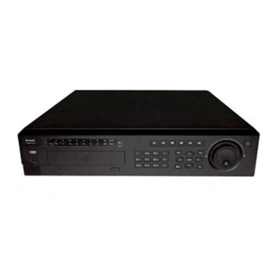
Front Panel The front panel is shown as in F igure 2- 1 6 6 7 H Figure 2- 1 The Front Panel of CADVR-04D Please refer to the following sheet for front panel button information. Name Icon Function... - Page 23 Increase/decrease numeral. Assistant function such as PTZ menu. Shift current activated control, Left/2 Right/3 During playback, click these buttons to control playback bar. Confirm current operation Enter ENTER Go to default button Go to menu Go to previous menu, or cancel current operation. During playback, click it to restore real-time monitor mode.
-
Page 24: Rear Panel
In normal playback or pause mode, click this button to reverse playback Reverse/Pause In reverse playback, click this button to pause playback. Fast play Various fast speeds and normal playback. Slow play Multiple slow play speeds or normal playback. In playback mode, playback the next video Play Next │... -
Page 25: Figure 2- 2 The Rear Panel Of Cadvr-04D
Figure 2- 2 The Rear Panel of CADVR-04D Please refer to the following sheet for detailed information. Description GND port Power input port Power button DB25 port ( 5th to 16th-channel audio input port) 1st to 4th-channel audio input Loop video output... -
Page 26: Connection Sample
Connection Sample Please refer to for connection sample. F igure 2- 3 6 6 9 H Figure 2- 3 Device Connection Remote Control The remote control interface is shown as in F igure 2- 4 6 7 0 H Please note remote control is not our standard accessory and it is not included in the accessory bag. -
Page 27: Figure 2- 4 Remote Controller
Figure 2- 4 Remote Controller Please refer to the following sheet for detailed information. Function Record search Multiple-window switch 0-9 number keys ESC, Cancel Reserved, not effective for HD-DVR-7016 Confirm /menu key Direction keys Auxiliary function key Remote address switch Previous Backward playback Slow play... -
Page 28: Mouse Control
Mouse Control Left click System pops up password input dialogue box if you have not logged mouse In real-time monitor mode, you can go to the main menu. When you have selected one menu item, left click mouse to view menu content. - Page 29 Double left Implement special control operation such as double click one item in click mouse the file list to playback the video. In multiple-window mode, double left click one channel to view in full-window. Double left click current video again to go back to previous multiple- window mode.
-
Page 30: Virtual Keyboard & Front Panel
Virtual Keyboard & Front Panel Virtual Keyboard The system supports two input methods: numeral input and English character (small and capitalized) input. Move the cursor to the text column, the text is shown as blue, input button pops up on the right. Click that button to switch between numeral input and English input (capitalized and small), Use >... -
Page 31: Installation And Connections
Installation and Connections All the installation and operations here should conform Note to your local electrical safety rules Check Unpacked DVR When you receive the DVR from the forwarding agent, please check whether there is any visible damage. The protective materials used for the package of the DVR can protect most accidental clashes during transportation. -
Page 32: Hdd Installation
HDD Installation This series DVR max supports 8 SATA HDDs. Please use HDD of 7200rpm or higher. It has no requirement for HDD capacity. You can refer to the appendix for recommended HDD brand. Please follow the instructions below to install hard disk. 1. -
Page 33: Rack Installation
7. Unfasten the HDD power cable. Insert the HDD power cable. 9. Use the special data cable to connect the HDD and the SATA port. Close the chassis and fix the screws to secure firmly. After completing HDD installation, please check the connection of the data ribbon and power cord, and remount the upper cover with screws fastened. -
Page 34: Connecting Power Supply
Please install from the bottom to the top. If there are more accessories connected in the rack, please take precaution measures in case the rack power is overload. Connecting Power Supply Please check input voltage and device power button match or not. We recommend you use UPS to guarantee steady operation, DVR life span, and other peripheral equipments operation such as cameras. -
Page 35: Connecting Video Output
Please use high quality, sound shielded BNC. Please select suitable BNC model according to the transmission distance. If the distance is too long, you should use twisted pair cable, and you can add video compensation devices or use optical fiber to ensure video quality. -
Page 36: Connecting Audio Input & Output, Bidirectional Audio
Using TV as video output device is not a reliable substitution method. You also need to reduce the working hour and control the interference from power supply and other devices. The low quality TV may result in device damage. Figure 3- 2 Connecting Video Output Connecting Audio Input &... -
Page 37: Audio Output
Figure 3- 3 Audio Input Audio Output The audio output signal parameter is usually over 200mv 1KΩ (BNC). It can directly connect to low impedance earphone, active sound box or amplifier-drive audio output device. If the sound box and the pick-up cannot be separated spatially, it is easy to arouse squeaking. -
Page 38: Alarm Input And Output Connection
Alarm Input and Output Connection Please refer to the following sheet for alarm input and output connection. F igure 3-5. X 2 8 7 H 2 8 7 H 2 8 7 H Figure 3- 5 Alarm Input and Output Connection There are two alarm input types for you to select: normal open (NO) and normal close (NC). - Page 39 c. Alarm input needs the low level voltage signal. d. Alarm input mode can be either NC (normal Open) or NO (Normal Close) e. When you are connecting two DVRs or you are connecting one DVR and one other device, please use a relay to separate them, 2.
-
Page 40: Alarm Input And Output Details
Alarm Input and Output Details You can refer to the following sheet and F igure 3-6 for alarm input and X 2 8 8 H 2 8 8 H 2 8 8 H output information. Important Please refer to the specifications for the alarm input and output channel amount. -
Page 41: Alarm Input Port
Earth cable. 485 A/B 485 communication port. They are used to control devices such as PTZ. Please parallel connect 120TΩ between A/B cables if there are too many PTZ decoders. Alarm Input Port Please refer to the following sheet for more information. Normal open or Normal close type. -
Page 42: Alarm Output Port
Alarm Output Port Provide power to peripheral alarm device. To avoid overloading, please read the following relay parameters sheet carefully. RS485 A/B cable is for the A/B cable of the PTZ decoder. Relay Specification JRC-27F Model: Silver Material of the touch Rating Rated switch capacity... -
Page 43: Rs232
RS232 You can connect the DVR with POS or Keyboard through RS232. With POS system, the DVR can communicate through RS232 and network. For the POS system, the DVR can integrate the text content and even search the record through the info. The series DVR also support NKB operation. -
Page 44: Other Interfaces
Other Interfaces There are still other interfaces on the DVR, such as USB ports. You can refer to the for more information. F igure 3- 8 6 7 3 H Figure 3- 8 Other Interfaces... -
Page 45: Overview Of Navigation And Controls
Overview of Navigation and Controls Note:All the operations listed below are based on the 2U series product. Before operation, please make sure: You have properly installed HDD and all the cable connections. The provided input power and the device power are matched. The external power shall be DC 12V. -
Page 46: Figure 4-1 Startup Wizard
Figure 4-1 Startup Wizard The system login interface is shown as in F igure 4-2 6 7 5 H System consists of four accounts: Username: admin. Password: admin. (administrator, local and network) Username: 888888. Password: 888888. (administrator, local only) Username: 666666. Passwords: 666666(Lower authority user who can only monitor, playback, backup and etc.) Username: default. -
Page 47: Main Menu
Figure 4-2 Menu Login Main Menu After you logged in, the system main menu is shown as below. See F igure 4-3 6 7 6 H There are total six icons: search, information, setting, backup, advanced and shutdown. You can move the cursor to highlight the icon, and then double click mouse to enter the sub-menu. -
Page 48: Logout
Logout There are two ways for you to log out. One is from menu option: In the main menu, click shutdown button, you can see an interface is shown as below. See F igure 4-4 6 7 7 H Figure 4-4 Logout Menu There are several options for you. -
Page 49: Replace Button Battery
Replace Button Battery Please make sure to use the same battery model if possible. We recommend replace battery regularly (such as one-year) to guarantee system time accuracy. Note: Before replacement, please save the system setup, otherwise, you may lose the data completely! Manual Record Live Viewing After you logged in, the system is in live viewing mode. -
Page 50: Manual Record
Figure 4-6 Preview Zoom Function Preview zoom button Manual record Note: You need to have proper rights to implement the following operations. Please make sure the HDD has been properly installed. Manual record menu There are two ways for you to go to manual record menu. Right click mouse or in the main menu, Advanced->Manual Record. -
Page 51: Figure 4-7 Recording Control Menu
Manual: The highest priority. After manual setup, all selected channels will begin ordinary recording. Schedule: Channel records as you have set in recording setup (Main Menu->Setting->Schedule) Stop: All channels stop recording. Figure 4-7 Recording Control Menu Enable/disable record Please check current channel status: “○” means it is not in recording status, “●”... -
Page 52: Figure 4-9 Automatic Recording In All Channels
All channel schedule record Please highlight “ALL” after “Schedule”. See F igure 4-9 6 8 2 H When system is in schedule recording, all channels will record as you have previously set (Main menu->Setting->Schedule). The corresponding indication light in front panel will turn on. Figure 4-9 Automatic Recording in All Channels All channel manual record Please highlight “ALL”... -
Page 53: Search & Playback
Stop all channel recording Please highlight “ALL” after “Stop”. See F igure 4-11 6 8 4 H System stops all channel recording no matter what mode you have set in the menu (Main menu->Setting->Schedule) Figure 4-11 Stop Recording in All Channels Search &... -
Page 54: Figure 4-12 Record Search Menu
Figure 4-12 Record Search Menu Please refer to the following sheet for more information. Function Name Display Here is to display the searched picture or file. window Support 1/4/9/16-window playback. Here you can select to search the picture or the recorded file. When there is displayed picture on the left pane, you can set the corresponding setup Search... - Page 55 The blue highlighted date means there is picture or file. Otherwise, there is no picture or file. Calendar In any play mode, click the date you want to see, you can see the corresponding record file trace in the time bar. Playback mode:1/4/9/16.
- Page 56 Backward play In normal play mode, left click the button, the file begins backward play. Click it again to pause current play. In backward play mode, click ►/ to restore normal play. In playback mode, click it to play the next or the previous section.
- Page 57 The option includes: 24H, 12H, 1H and 30M. The smaller the unit, the larger the zoom rate. You can accurately set the time in the time bar to playback the record. Time bar unit The time bar is beginning with 0 o'clock when you are setting the configuration.
-
Page 58: Schedule
Note: All the operations here (such as playback speed, channel, time and progress) have relationship with hardware version. Some series DVRs do not support some functions or playback speeds. Schedule After system booted up, it is in default 24-hour regular mode. You can set record type and time in schedule interface. -
Page 59: Figure 4-13 Schedule Setting
Record types: There are four types: regular, motion detection (MD), Alarm, MD & alarm. Please highlight icon to select the corresponding function. After completing all the setups please click save button, system goes back to the previous menu. At the bottom of the menu, there are color bars for your reference. Green color stands for regular recording, yellow color stands for motion detection and red color stands for alarm recording. - Page 60 Redundancy Redundancy function allows you to memorize record file in several disks. When there is file damage occurred in one disk, there is a spare one in the other disk. You can use this function to maintain data reliability and safety. In the main menu, from Setting to Schedule, you can highlight redundancy button to enable this function.
-
Page 61: Snapshot
Figure 4-14 redundancy setup Playback or search in the redundant disk. There are two ways for you to playback or search in the redundant disk. Set redundant disk(s) as read-only disk or read-write disk (Main menu->Advanced->HDD management). See .System F igure 4-14 6 8 9 H needs to reboot to get setup activated. -
Page 62: Figure 4-15 Schedule Snapshot Setting
Figure 4-15 Schedule Snapshot Setting Activation Snapshot... -
Page 63: Figure 4-16 Activation Snapshot Setting
Please follow the steps listed below to enable the activation snapshot function. After you enabled this function, system can snapshot when the corresponding alarm occurred. In Encode interface, click snapshot button to input snapshot mode, size, quality and frequency. In General interface please input upload interval. In Detect interface please enable snapshot function for specified channels. -
Page 64: Image Ftp
Priority Please note the activation snapshot has the higher priority than schedule snapshot. If you have enabled these two types at the same time, system can activate the activation snapshot when alarm occurs, and otherwise system just operates the schedule snapshot. Image FTP In Network interface, you can set FTP server information. -
Page 65: Snapshot Disk (For Special Series Only)
Figure 4-17 Image FTP Stting Please input the corresponding information here, if you just upload the image FTP. Snapshot Disk (For special series only) Set one disk as snapshot (Main menu->Advanced->HDD management) and then click execute button. See . System F igure 4-18 6 9 3 H needs to reboot to get current setup activated. -
Page 66: Figure 4-19 Search Image Via Web
All scheduled snapshot files or activated snapshot files will be memorized in the snapshot disk. You can search the corresponding images via Web. See F igure 4-19 6 9 4 H Figure 4-19 Search Image Via Web Select search engine here Select a file and then click here to view image content. -
Page 67: Detect
Detect Go to Detect Menu In the main menu, from Setting to Detect, you can see motion detect interface. See .There is three detection types: motion F igure 4-20 6 9 5 H detection, video loss, camera masking. Motion Detect Detection menu is shown as below. - Page 68 Show message: System can pop up a message to alarm you in the local host screen if you enabled this function. Alarm upload: System can upload the alarm signal to the network (including alarm centre) if you enabled current function. Send email: System can send out email to alert you when alarm occurs.
-
Page 69: Figure 4-20 Motion Detect Setting
Figure 4-20 Motion Detect Setting Figure 4-21 Motion Detection Zone Setting... -
Page 70: Figure 4-22 Ptz Activation Setting
Figure 4-22 PTZ Activation Setting Figure 4-23 Armed Period Setting Figure 4-24 Business Day and Non-Business Day Setting... -
Page 71: Video Loss
Video Loss , select video loss from the type list. You can see the F igure 4-20 7 0 3 H interface is shown as in .This function allows you to be F igure 4-25 7 0 4 H informed when video loss phenomenon occurred. You can enable alarm output channel and then enable show message function. -
Page 72: Alarm Setup And Alarm Activation
You can enable preset/tour/pattern activation operation when video loss occurs. Please refer to chapter 4.5.2 motion detection for detailed information. Note: In Detect interface, copy/paste function is only valid for the same type, which means you can not copy a channel setup in video loss mode to camera masking mode. -
Page 73: Alarm Setup
Alarm setup Alarm interface is shown as below. See F igure 4-27 7 0 7 H Alarm in: Here is for you to select channel number. Event type: There are two types. One is local input and the other is network input. -
Page 74: Figure 4-27 Local Alarm Setting
Buzzer: Highlight the icon to enable this function. The buzzer beeps when alarm occurs. For snapshot operation, please refer to chapter 4.4.2. Please highlight icon to select the corresponding function. After setting all the setups please click save button, system goes back to the previous menu. -
Page 75: Backup
Figure 4-29 Period Setting Figure 4-30 Business Days and Non-Business Days Settings Backup DVR support USB device backup and network download. Here we introduce USB backup. You can refer to Chapter 7 Web Client Operation for network download backup operation. Detect Device Click backup button, you can see an interface is shown as in F igure... -
Page 76: Backup
You can view backup device name and its total space and free space. The device includes USB burner, flash disk, SD card, and portable HDD. Figure 4-31 Device Detection Menu of Backup Backup Select backup device and then set channel, file start time and end time. -
Page 77: Figure 4-32 Backup Menu With Search Results
Figure 4-32 Backup Menu with Search Results Click backup button, system begins burning. At the same time, the backup button becomes stop button. You can view the remaining time and process bar at the left bottom. File format: Click the file format; you can see there are two options: DAV/ASF. -
Page 78: Ptz Control And Color Setup
One key backup: It includes three steps: the search, select all, start the backup. You can skip the above three steps and then copy all the searched files directly. The file name format usually is: SN_CH+channel number+time Y+M+D+H+M+S. In the file name, the YDM format is the same as you set in general interface. -
Page 79: Ptz Setup
PTZ Setup Note: The camera video should be in the current screen. Before setup, please check the following connections are right: PTZ and decoder connection is right. Decoder address setup is right. Decoder A (B) line connects with DVR A (B) line. Boot up the DVR, input user name and password. -
Page 80: Figure 4-35 Context Menu
After completing all the setting please click save button. In one window display mode, right click mouse (click “Fn” Button in the front panel or click “Fn” key in the remote control). The interface is shown as in F igure 4-35 7 1 6 H Figure 4-35 Context Menu Click Pan/Tilt/Zoom, the interface is shown as below. -
Page 81: Preset/ Patrol/Pattern/Scan
Figure 4-36 PTZ Control Menu , please click direction arrows (See ) to adjust F igure 4-36 F igure 4-37 7 1 8 H 7 1 9 H PTZ position. There are total 8 direction arrows. Figure 4-37 Direction Arrows Here is a sheet for you reference. -
Page 82: Figure 4-38 Ptz Setup Menu
Preset Tour Pattern Border Figure 4-38 PTZ Setup Menu , click page switch button, the interface is shown as in F igure 4-36 X 3 2 8 H 3 2 8 H 3 2 8 H 7 2 2 H F igure 4-38 7 2 3 H Here you can activate the following functions:... -
Page 83: Preset Setup
Figure 4-39 PTZ Function Menu Note: Preset, tour and pattern all need the value to be the control parameter. You can define it as you require. You need to refer to your speed dome user’s manual for Aux definition. In some cases, it can be used for special process. The following setups are usually operated in the F igure 4-36 F igure... -
Page 84: Activate Preset
Figure 4-40 Preset Setting Activate Preset , please input preset number in the No. blank, and click F igure 4-39 7 3 0 H preset button. Patrol setup (Tour Setup) In Figure 4-38, click patrol button. The interface is shown as in F igure 7 3 1 H .Input preset number and add this preset to a patrol (tour). -
Page 85: Activate Patrol (Tour)
Figure 4-41 Tour Setting Activate Patrol (tour) , input patrol (tour) number in the No. blank and click F igure 4-39 X 3 4 1 H 3 4 1 H 3 4 1 H 7 3 2 H patrol button Pattern Setup , click pattern button and then click “begin”... -
Page 86: Activate Pattern Function
Figure 4-42 Pattern Setting Activate Pattern Function Figure 4-39, input mode value in the No. blank, and click pattern X 3 4 6 H 3 4 6 H 3 4 6 H button. Auto Scan Setup Figure 4-38, click border button. The interface is shown as in Figure X 3 4 7 H 3 4 7 H 3 4 7 H X 3 4 8 H 3 4 8 H 3 4 8 H... -
Page 87: Activate Auto Scan
Figure 4-43 Auto Scan Setting Activate Auto Scan , click “Auto Scan” button, the system begins auto scan. F igure 4-39 7 3 8 H Correspondingly, the auto scan button becomes Stop button. Click stop button to terminate scan operation. Flip , click page switch button, you can see an interface is F igure 4-39... -
Page 88: Figure 4-44 Auxiliary Setting
Figure 4-44 Auxiliary Setting... -
Page 89: Understanding Of Menu Operations And Controls
Understanding of Menu Operations and Controls Menu Tree This series DVR menu tree is shown as below. - Page 90 Backup Information HDD Info Version Online Users Setting General Encode Schedule RS232 Menu Network Alarm Detect Pan/ Tilt/Zoom Display Default Search Advanced HDD Management Alarm Output Abnormity Manual Record Account Auto Maintain TV Adjust Video Matrix Title Overlay Config Backup Shutdown...
-
Page 91: Main Menu
Main Menu After you logged in, the system main menu is shown as below. See There are total six icons: search, Information, setting, backup, F igure 5-1 7 4 2 H advanced and shutdown. Move the cursor to highlight the icon, then double click mouse to enter the sub-menu. -
Page 92: General
Figure 5-2 Setting General General setting includes the following items. See F igure 5-3 X 3 5 7 H 3 5 7 H 3 5 7 H System time: Here is for you to set system time Date format: There are three types: YYYYY-MM-DD: MM-DD-YYYYY or DD-MM-YYYY. - Page 93 languages listed here are optional. Slight difference maybe found in various series.) HDD full: Here is for you to select working mode when hard disk is full. There are two options: stop recording or rewrite. If current working HDD is overwritten or the current HDD is full while the next HDD is no empty, then system stops recording, If the current HDD is full and then next HDD is not empty, then system overwrites the previous files.
-
Page 94: Encode
Figure 5-3 General Setting Figure 5-4 DST Setup Menu (Week) Figure 5-5 DST setup menu (Date) Encode Encode setting includes the following items. See F igure 5-6 7 4 6 H Please note some series do not support extra stream. - Page 95 Channel: Select the channel you want. Type: Please select from the dropdown list. There are three options: regular/motion detect/alarm. You can set the various encode parameters for different record types. Compression: System supports H.264. Resolution: System supports various resolutions, you can select from the dropdown list.
-
Page 96: Figure 5-6 Encode Menu
Channel display: You can select system displays channel number or not when you playback. Please click set button and then drag the title to the corresponding position in the screen. Please highlight icon to select the corresponding function. Figure 5-6 Encode Menu Figure 5-7 Encode Menu... -
Page 97: Schedule
Schedule Please refer to chapter 4.4 schedule. RS232 RS232 interface is shown as below. There are five items. See F igure 5-8 7 4 8 H Function: There are various devices for you to select. Console is for you to use the COM or mini-end software to upgrade or debug the program. The control keyboard is for you to control the device via the special keyboard. -
Page 98: Network
Figure 5-8 RS232 Setup Menu Network Here is for you to input network information. See F igure 5-9 7 4 9 H IP address: Here you can input IP address. DHCP: It is to auto search IP. When enable DHCP function, you can not modify IP/Subnet mask /Gateway. -
Page 99: Figure 5-9 Network Setup Menu
Preferred DNS server: DNS server IP address. Alternate DNS server: DNS server alternate address. Transfer mode: Here you can select the priority between fluency/video qualities. LAN download: System can process the downloaded data first if you enable this function. The download speed is 1.5X or 2.0X of the normal speed. -
Page 100: Figure 5-10 Advanced Settings
Figure 5-10 Advanced Settings IP Filter IP filter interface is shown as in . You can add IP in the F igure 5-11 7 5 1 H following list. The list supports max 64 IP addresses. Please note after you enabled this function, only the IP listed below can access current DVR. - Page 101 You need to install SNTP server (Such as Absolute Time Server) in your PC first. In Windows XP OS, you can use command “net start w32time” to boot up NTP service. NTP setup interface is shown as in F igure 5-12 7 5 2 H Host IP: Input your PC address.
-
Page 102: Figure 5-12 Ntp Setup Menu
Hawaii GMT-10 Alaska GMT-9 Pacific Time(P.T) GMT-8 American Mountain Time(M.T) GMT-7 American Central Time(C.T) GMT-6 American Eastern Time(E.T) GMT-5 Atlantic Time GMT-4 Brazil GMT-3 Middle Atlantic Time GMT-2 Figure 5-12 NTP Setup Menu... -
Page 103: Figure 5-13 Multiple Cast Setup Menu
Multiple Cast Setup Multiple-cast setup interface is shown as in F igure 5-13 7 5 3 H Figure 5-13 Multiple Cast Setup Menu Here you can set a multiple cast group. Please refer to the following sheet for detailed information. ·... -
Page 104: Figure 5-14 Pppoe Setup Menu
· Can not be used in Internet transmission · Used for multiple cast broadcast in limited space Except the above mentioned addresses of special meaning, you can use other addresses. For example: Multiple cast IP: 235.8.8.36 Multiple cast PORT: 3666 After you logged in the Web, the Web can automatically get multiple cast address and add it to the multiple cast groups. -
Page 105: Figure 5-15 Ddns Setup Menu
DDNS Setup DDNS setup interface is shown as in F igure 5-15 7 5 5 H You need a PC of fixed IP in the internet and there is the DDNS software running in this PC. In other words, this PC is a DNS (domain name server). - Page 106 Private DDNS function shall work with special DDNS server and special Professional Surveillance Software (CADVR-CS). UPNP The UPNP protocol is to establish a mapping relationship between the LAN and the WAN. Please input the router IP address in the LAN in F igure 5-9 .
-
Page 107: Figure 5-16 Upnp Menu
Double click one item; you can change the corresponding mapping F igure 5-17 information. See 7 5 9 H Important: When you are setting the router external port, please use 1024~5000 port. Do not use well-known port 1~255 and the system port 256~1023 to avoid conflict. - Page 108 SMTP server: Please input your email SMTP server IP here. Port: Please input corresponding port value here. User name: Please input the user name to login the sender email box. Password: Please input the corresponding password here. Sender: Please input sender email box here. Title: Please input email subject here.
-
Page 109: Figure 5-18 Email Setup Menu
Figure 5-18 Email Setup Menu Figure 5-19 Mail Test Info You need to download or buy FTP service tool (such as Ser-U FTP SERVER) to establish FTP service. Please install Ser-U FTP SERVER first. From “start” -> “program” -> Serv-U FTP Server -> Serv-U Administator. Now you can set user password and FTP folder. -
Page 110: Figure 5-20 Ftp Server Setup Menu
Figure 5-20 FTP Server Setup Menu You can use a PC or FTP login tool to test setup is right or not. For example, you can login user ZHY to F TP://10.10.7.7 and then test H 1 4 0 H 1 4 0 H 1 4 0 H 3 3 3 H T U U T H it can modify or delete folder or not. -
Page 111: Figure 5-22 Ftp Setup Menu
Here you can input FTP server address, port and remote directory. When remote directory is null, system automatically create folders according to the IP, time and channel. User name and password is the account information for you to login the FTP. -
Page 112: Alarm
Figure 5-23 FTP Test Info Alarm Centre This interface is reserved for you to develop. Alarm Please refer to chapter 4.6 Alarm Setup and Activation. Detect Please refer to chapter 4.5 Detect. Pan/Tilt/Zoom The pan/tilt/zoom setup includes the following items. Please select channel first. -
Page 113: Display
Baud rate: Select baud rate. Data bit: Select data bit. Stop bit: Select stop bit. Parity: There are three choices: none/odd/even. After completed all the setups please click save button, system goes back to the previous menu. For detailed setup, please refer to chapter 4.9 preset/patrol/pattern/scan. Figure 5-24 PTZ Setup Menu Display Display setup interface is shown as below. - Page 114 Time display: You can select to display time or not when system is playback. Channel display: You can select to channel name or not when system is playback. Resolution: There are four options: 1280×1024(default),1280× 720,1024×768,800×600. Please note the system needs to reboot to activate current setup.
-
Page 115: Figure 5-25 The Display Setup Menu
Figure 5-25 The Display Setup Menu , click modify button after channel. You can see an F igure 5-25 7 6 9 H interface is shown as in . Please note all your modification F igure 5-26 7 7 0 H here applies to local end only. -
Page 116: Default
two icons: stands for enabling window switch and stands for disabling window function. See F igure 5-27 7 7 1 H Figure 5-27 The Sample of Tour Mode Default Click default icon, system pops up a dialogue box. You can highlight to restore default factory setup. -
Page 117: Search
After all the setups please click save button, system goes back to the previous menu. Warning! System menu color, language, time display mode, video format, IP address, user account will not maintain previous setup after default operation! Figure 5-28 Default Setup Menu Search Please refer to chapter 4.3 Search. -
Page 118: Hdd Management
Figure 5-29 Advanced Menu HDD Management Here is for you to view and implement hard disk management. See F igure 5-30 7 7 3 H You can see current HDD type, status, capacity and record time. When HDD is working properly, system is shown as O. When HDD error occurred, system is shown as X. -
Page 119: Figure 5-30 Hdd Management Setup Menu
Figure 5-30 HDD Management Setup Menu Please highlight icon to select the corresponding function. Figure 5-31 Abnormity Setup Menu For the HDD group setup operation, please note: Each channel’s records can be stored into the specified HDD Group. Each HDD Group is corresponding to several hard disks, while one hard disk is only included in one HDD Group. - Page 120 Each channel is only corresponding with one HDD Group, while one HDD Group can store records from several channels. HDD Group is only available for read-write HDD and self-defined disks, other types of hard disks cannot be set as HDD Group. Important: e-SATA also supports this function, you can manage e-SATA hard disk as local hard disk.
-
Page 121: Figure 5-32 Different Hdd Group Setting Menu
Figure 5-32 Different HDD Group Setting Menu , you can see the 6th and 7th position hard disks both F igure 5-33 7 7 8 H belong to HDD Group 2. Important Once you change the HDD Group settings, system will pack the records and snapshots, and then reboot. -
Page 122: Figure 5-33 Same Hdd Group Setting Menu
Figure 5-33 Same HDD Group Setting Menu Channels Setting Click the button named with “Channels Settings” at the top right corner of the , system will pop up an interface shown as in F igure 5-30 F igure 7 7 9 H 7 8 0 H 5-34 When you are setting the configurations of the channels setting, please... -
Page 123: Abnormity
Figure 5-34 HDD Group 1 Channel Setting Figure 5-35 HDD Group 2 Channel Setting Abnormity Abnormity interface is shown as in F igure 5-36 7 8 3 H Event type: There are several options for you such as disk error, no disk, disconnection, IP conflict and etc. -
Page 124: Alarm Output
Alarm upload: System can upload the alarm signal to the network (including alarm centre) if you enabled current function. Send email: System can send out email to alert you when alarm occurs. Buzzer: Highlight the icon to enable this function. The buzzer beeps when alarm occurs. -
Page 125: Manual Record
Figure 5-37 Alarm Output Setup Menu Manual Record Please refer to chapter 4.2.2 manual record. Account Here is for you to implement account management. See F igure 5-38 7 8 5 H Here you can: Add new user Modify user Add group Modify group Modify password. - Page 126 There can be backspace in the middle. The string includes the valid character, letter, number, underline, subtraction sign, and dot. System account adopts two-level management: group and user. No limit to group or user amount. For group or user management, there are two levels: admin and user. The user name and group name can consist of eight bytes.
-
Page 127: Figure 5-38 Account Management Menu
Figure 5-38 Account Management Menu Modify Password Click password button, the interface is shown as in F igure 5-39 7 8 6 H Here you can modify account password. Please select the account from the dropdown list, input the old password and then input the new password twice. -
Page 128: Figure 5-39 Modify Password
Figure 5-39 Modify Password Add/Modify Group Click add group button, the interface is shown as below. See F igure 5-40 7 8 7 H Here you can input group name and then input some memo information if necessary. There are total 60 rights such as control panel, shut down, real-time monitor, playback, record, record file backup, PTZ, user account, system information view, alarm input/output setup, system setup, log view, clear log, upgrade system, control device and etc. -
Page 129: Figure 5-40 Add Group
Figure 5-40 Add Group Add/Modify User Click add user button, the interface is shown as in F igure 5-41 7 8 9 H Please input the user name, password, select the group it belongs to from the dropdown list. Then you can check the corresponding rights for current user. For convenient user management, usually we recommend the general user right is lower than the admin account. -
Page 130: Auto Maintain
Figure 5-41 Add User Auto Maintain Here you can set auto-reboot time and auto-delete old files setup. You can set to delete the files for the specified days. See F igure 5-42 7 9 1 H You can select proper setup from dropdown list. After all the setups please click save button, system goes back to the previous menu. -
Page 131: Tv Adjust
TV Adjust Here is for you to adjust TV output setup. See F igure 5-43 7 9 2 H Please drag slide bar to adjust each item. After all the setups please click OK button, system goes back to the previous menu. -
Page 132: Card Overlay
Figure 5-44 Video Matrix Menu Card Overlay The card overlay function is for financial areas. It includes Sniffer, information analysis and title overlay function. The Sniffer mode includes COM and network. COM Type The COM interface is shown as below. See F igure 5-46 7 9 4 H Protocol: Please select from the dropdown list. -
Page 133: Figure 5-45 Text Overlay(Com Type)
Figure 5-45 Text Overlay(COM Type) Network Type The network type interface is shown as below. See F igure 5-46 7 9 5 H Here we take the ATM/POS protocol to continue. There are two types: with or without the protocol according to client’s requirements. -
Page 134: Figure 5-46 Text Overlay(Network Type)
Figure 5-46 Text Overlay(Network Type) Without the protocol For the ATM/POS without the protocol, the interface is shown as in F igure 5-47 7 9 6 H Source IP refers to host IP address that sends out information (usually it is the device host.) Destination IP refers to other systems that receive information. -
Page 135: Figure 5-47 Atm/Pos
Figure 5-47 ATM/POS Click Data button you can see an interface is shown as in F igure 5-48 7 9 7 H Here you can set offset value, length, title according to your communication protocol and data package. . Figure 5-48 Data Format... -
Page 136: Config File Backup
Config File Backup The configuration file backup interface is shown as below. See F igure 7 9 8 H 5-49 This function allows you to copy current system configuration to other devices. Figure 5-49 Config File Backup Information Here is for you to view system information. There are total five items: HDD (hard disk information), BPS (data stream statistics), Log and version, and online user. -
Page 137: Hdd Information
Figure 5-50 Info Menu HDD Information Here is to list hard disk type, total space, free space, video start time and status. See .○ means current HDD is normal. X F igure 5-51 X 3 9 1 H 3 9 1 H 3 9 1 H 8 0 0 H means there is error. -
Page 138: Bps
Figure 5-51 HDD Info Menu Tips: Please click Fn button or left click mouse to view HDD record time and HDD type and time. Here is for you to view current video data stream (KB/s) and occupied hard disk storage (MB/h). See F igure 5-52 8 0 1 H Figure 5-52 BPS Display Menu... -
Page 139: Log
Here is for you to view system log file. System lists the following information. See F igure 5-53 8 0 2 H Log types include system operation, configuration operation, data management, alarm event, record operation, log clear and etc. Pleased select start time and end time, then click search button. You can view the log files. -
Page 140: Version
Click the Details button or double click the log item, you can view the detailed information. See F igure 5-54 8 0 3 H Figure 5-54 Log Details Version Here is for you to view some version information. See F igure 5-55 8 0 4 H Channel Alarm in... -
Page 141: Online Users
Alarm out System version: Build Date Figure 5-55 Version Menu Online Users Here is for you manage online users. See F igure 5-56 8 0 5 H You can disconnect one user or block one user if you have proper system right. -
Page 142: Shutdown
Figure 5-56 Online Users Menu Shutdown Double click shutdown button, system pops up a dialogue box for you to select. See F igure 5-57 8 0 6 H Logout menu user: log out menu. You need to input password when you login the next time. -
Page 143: Figure 5-57 Shutdown Menu
Figure 5-57 Shutdown Menu... -
Page 144: About Auxiliary Menu
About Auxiliary Menu Go to Pan/Tilt/Zoom Menu In the one-window surveillance mode, right click mouse (click “fn” Button in the front panel or click AUX key in the remote control). The interface is shown as below: See F igure 6-1 X 3 9 7 H 3 9 7 H 3 9 7 H Figure 6- 1 Context Menu Click Pan/Tilt/Zoom, the interface is shown as in... -
Page 145: Figure 6- 2 Ptz Control Menu
Figure 6- 2 PTZ Control Menu In X399H399H399HFigure 6-2X, please click direction arrows (See X400H400H400HFigure 6-3X ) to adjust PTZ position. There are totally eight direction arrows. (Please note there are only four direction arrows in DVR front panel.) Figure 6- 3 Direction Arrows Here is a sheet for you reference. -
Page 146: Preset /Patrol / Pattern /Border Function
Preset /Patrol / Pattern /Border Function F igure 6-2 click the set button. The interface is shown as below: X 4 0 2 H 4 0 2 H 4 0 2 H Here you can set the following items: Preset Patrol Pattern Border... -
Page 147: Preset Setup
Page Switch Figure 6- 5 PTZ Function Menu Preset Setup Note: The following setups are usually operated in the F igure 6-2 X 4 0 5 H 4 0 5 H 4 0 5 H F igure 6-5 F igure 6-6 X 4 0 6 H 4 0 6 H 4 0 6 H X 4 0 7 H 4 0 7 H 4 0 7 H F igure 6-2... -
Page 148: Activate Preset
Activate Preset F igure 6-6 please input preset number in the No. blank, and click X 4 1 1 H 4 1 1 H 4 1 1 H preset button. Patrol Setup F igure 6-5 , click patrol button. The interface is shown as in F igure 6-8 X 4 1 2 H 4 1 2 H 4 1 2 H X 4 1 3 H 4 1 3 H 4 1 3 H... -
Page 149: Activate Pattern Function
Please go to F igure 6-2 to modify zoom, focus, and iris. Go back to X 4 1 7 H 4 1 7 H 4 1 7 H F igure 6-9 and click end button. X 4 1 8 H 4 1 8 H 4 1 8 H You can memorize all these setups as pattern 1. -
Page 150: Activate Border Function
Figure 6- 9 Auto Scan Setting Activate Border Function F igure 6-6 , click auto scan button, the system begins auto scan. X 4 2 4 H 4 2 4 H 4 2 4 H Correspondingly, the auto scan button changes to stop button. Click stop button to terminate scan operation. -
Page 151: Figure 6- 10 Auxiliary Setting
Figure 6- 10 Auxiliary Setting... -
Page 152: Web Client Operation
WEB CLIENT OPERATION There might be slightly difference in the interface due to different series. Network Connection Before web client operation, please check the following items: Network connection is right DVR and PC network setup is right. Please refer to network setup(main menu->setting->network) Use order ping ***.***.***.***(* DVR IP address) to check connection is OK or not. -
Page 153: Figure 7- 1 Sample Of Ie Login
Figure 7- 1 Sample of IE Login Input your IP address here. System pops up warning information to ask you whether install webrec.cab control or not. Please click yes button. If you can’t download the ActiveX file, please modify your settings as follows. -
Page 154: Figure 7- 3 Web Login Window
After installation, the interface is shown as below. See F igure 7-3 X 4 3 0 H 4 3 0 H 4 3 0 H Please input your user name and password. Default factory name is admin and password is admin. Note: For security reasons, please modify your password after you first login. -
Page 155: Figure 7- 4 Window Switch Menu
After you logged in, you can see the main window. See F igure 7-6 X 4 3 1 H 4 3 1 H 4 3 1 H This main window can be divided into the following sections. Section 1: there are five function buttons: configuration (chapter 7.3), search (chapter 7.4), alarm (chapter 7.5), about (chapter 7.6), log out (chapter 7.7). -
Page 156: Real-Time Monitor
Figure 7- 5 Main Menu of Web Client Section1 Section 3 Section 2 Section 5 Real-time Monitor In section 2, left click the channel name you want to view, you can see the corresponding video in current window. On the top left corner, you can view device IP, channel number, network monitor bit stream. -
Page 157: Figure 7- 8 Switch Between The Main Stream And Extra Stream
1: Digital zoom: Click this button and then left drag the mouse in the zone to zoom in. right click mouse system restores original status. 2: Change show mode: resize or switch to full screen mode. 3: Local record. When you click local record button, the system begins recording and this button becomes highlighted. -
Page 158: Ptz
Local Play The Web can playback the saved (Extension name is dav) files in the PC-end. Click local play button, system pops up the following interface for you to select local play file. See F igure 7-10. X 4 3 6 H 4 3 6 H 4 3 6 H Figure 7- 9 Selection Menu of Local Play File Before PTZ operation, please make sure you have properly set PTZ protocol. -
Page 159: Figure 7- 10 Ptz Control Menu
Figure 7- 10 PTZ Control Menu 3D Intelligent Positioning You can click this icon to display or hide the PTZ control platform. Direction key and 3D positioning key In Figure 7-10, there are eight direction keys. In the middle of the eight direction keys, there is a 3D intelligent positioning key. -
Page 160: Figure 7- 11 Ptz Setup Menu
System supports eight-level speed. You can select from the dropdown list. Speed 2 is faster than speed 1. Zoom/Focus/Iris Here is a sheet for you reference. Name Function key Function Function key Function Zoom Near Focus Near Iris close Open In Figure 7-11, click PTZ setup button you can see the following interface. -
Page 161: Auto Tour
F igure 7-12 , you can input pattern value and then click start record X 4 4 0 H 4 4 0 H 4 4 0 H button to begin PTZ movement. Please go back to Figure 7-11 to implement camera operation. Then you can click stop record button. Now you have set one pattern. -
Page 162: Color
Figure 7- 12 Assistant Setup Menu Color Click color button in section 3, the interface is shown as F igure 7-14 X 4 4 4 H 4 4 4 H 4 4 4 H Here you can select one channel and then adjust its brightness, contrast, hue and saturation. -
Page 163: Picture Path And Record Path
Picture Path and Record Path Click more button in F igure 7-14 , you can see an interface is shown as X 4 4 5 H 4 4 5 H 4 4 5 H F igure 7-15 X 4 4 6 H 4 4 6 H 4 4 6 H Figure 7- 14 More Setup Menu Click the record item;... -
Page 164: Configure
Figure 7- 16 Path Setup Menu (for Record) Click reboot button, system pops up the following dialogue box. See Figure 7-18, Please click OK to reboot. Figure 7- 17 Reboot Dialog If there is local use logged in the system menu, or the Web logged in user has no right to reboot the device system pops up a dialogue box to alert you. -
Page 165: Figure 7- 18 Version Information Menu
Figure 7- 18 Version Information Menu HDD information Here you can view local storage status and network status including, free capacity and total capacity. See F igure 7-20 X 4 5 0 H 4 5 0 H 4 5 0 H Figure 7- 19 HDD Information Menu Here you can view system log. -
Page 166: Figure 7- 20 Log Information Menu
Figure 7- 20 Log Information Menu Click backup button, the interface is shown as in F igure 7-22 X 4 5 2 H 4 5 2 H 4 5 2 H Figure 7- 21 Log Backup Menu Please refer to the following sheet for log parameter information. Parameter Function Type... -
Page 167: System Configuration
Parameter Function Please input start time here. Start time Please input the end time here. End time Clear You can click this button to delete all displayed log files. Please note system does not support clear by type. Select one item and click this button, you can view the detailed log More information. -
Page 168: Figure 7- 23 Dst Setup Menu (Date)
Figure 7- 23 DST Setup Menu (Date) Figure 7- 24 DST Setup Menu (Week) Please refer to the following sheet for detailed information. Parameter Function Here is for you to modify system time. Please click Save button System after your completed modification Time Sync PC You can click this button to save the system time as your PC current... - Page 169 Here you can set day night save time begin time and end time. See Figure 7-24 and Figure 7-25. Language You can select the language from the dropdown list. Device needs to reboot to get the modification activated. There are two options: stop recording or overwrite the previous HDD Full files when HDD is full.
-
Page 170: Figure 7- 25 Encode Menu
Figure 7- 25 Encode Menu Figure 7- 26 Color Setting Menu Please refer to the following sheet for detailed information. Parameter Function Here is for you to select a monitor channel. Channel Here is to display current channel name. You can modify it. Channel Name Compression H.264... - Page 171 Parameter Function Main Stream It includes main stream, motion stream and alarm stream. You can select different encode frame rates form different recorded events. System supports active control frame function (ACF). It allows you to record in different frame rates. For example, you can use high frame rate to record important events, record scheduled event in lower frame rate and it allows you to set different frame rates for motion detection record and alarm record.
- Page 172 Parameter Function Cover area Here you can privacy mask the specified video in the monitor video. (privacy mask) One channel max supports 4 privacy mask zones. The privacy mask includes two options: Never/monitor. Never: It means do not enable privacy mask function. Monitor: the privacy mask zone can not be viewed in monitor mode.
-
Page 173: Figure 7- 27 Copy-To Menu
Figure 7- 27 Copy-To Menu Schedule Here you can set different periods for various days. There are max six periods in one day. See X457H457H457HFigure 7-29X Figure 7- 28 Schedule Setup Menu... -
Page 174: Figure 7- 29 Date And Time Setup Menu
Figure 7- 29 Date and Time Setup Menu Please refer to the following sheet for detailed information. Parameter Function Please select a channel first. Channel Please input pre-record value here. Pre-record System can record the three to five seconds video before activating the record operation into the file. -
Page 175: Figure 7- 30 Rs232 Setup Menu
Parameter Function Save You can click save button after you complete setup for one channel, or you can complete the whole setups and then click save button. Refresh Click this button to get device latest configuration information. RS232 The RS232 interface is shown as in F igure 7-31 X 4 6 1 H 4 6 1 H 4 6 1 H Figure 7- 30 RS232 Setup Menu... -
Page 176: Figure 7- 31 Network Setup Menu
Parameter Function There are five options: none/odd/even/space/mark. Parity System default setup is: Function: Console. Data bit: 8 Stop bit: 1 Baud bit: 115200 Parity: None. Network Network interface is shown as in F igure 7-32 X 4 6 2 H 4 6 2 H 4 6 2 H Figure 7- 31 Network Setup Menu Please refer to the following sheet for detailed information. - Page 177 Parameter Function DHCP Dynamically get IP address. You can get the device IP from the DHCP server if you enabled this function. TCP Port Default value is 37777. HTTP Port Default value is 80. UDP Port Default value is 37778. RTSP Port Default value is 554.
-
Page 178: Figure 7- 32 Email Setup Menu
Figure 7- 32 Email Setup Menu Please refer to the following sheet for detailed information. Parameter Function Input server address and then enable this function. SMTP Server Input port value here. Port The sender email account user name. User Name The sender email account password. -
Page 179: Figure 7- 33 Ddns Setup Menu
Please make sure your DVR support this function. Figure 7- 33 DDNS Setup Menu Please refer to the following sheet for detailed information. Parameter Function Server Type You can select DDNS protocol from the dropdown list and then enable DDNS function. The private DDNS protocol means you use your self-defined private protocol to realize DDNS function. -
Page 180: Figure 7- 34 Nas Setup Menu
Figure 7- 34 NAS Setup Menu Please refer to the following sheet for detailed information. Parameter Function Please select network storage protocol and then enable NAS enable NAS function. Input remote storage server IP address. Server IP Input Remote storage server port number. Port Log in user account. -
Page 181: Figure 7- 35 Ntp Setup Menu
Parameter Function Refresh Click this button to get device latest configuration information. The NTP interface is shown as in F igure 7-36 X 4 6 6 H 4 6 6 H 4 6 6 H Here you can realize network time synchronization. Please enable current function and then input server IP, port number, time zone and update interval. - Page 182 Cairo GMT+2 Moscow GMT+3 New Deli GMT+5 Bangkok GMT+7 Beijing (Hong Kong) GMT+8 Tokyo GMT+9 Sydney GMT+10 Hawaii GMT-10 Alaska GMT-9 Pacific Time(P.T) GMT-8 American Mountain Time(M.T) GMT-7 American Central Time(C.T) GMT-6 American Eastern Time(E.T) GMT-5 Atlantic Time GMT-4 Brazil GMT-3 Middle Atlantic Time GMT-2...
-
Page 183: Figure 7- 36 Alarm Setup Menu
Alarm Centre Alarm centre interface is shown as below. See Figure 7-37. This interface is for you to develop. The alarm signal can be uploaded to the alarm centre when there is local alarm. Please set the corresponding parameters such as server IP, port and etc. -
Page 184: Figure 7- 37 Advanced Setup
Device connects to the internet via PPPoE after reboot. You can get the IP address in the WAN from the IP address column. Note: After PPPoE successful dial, you need to go to the device local end to get device current IP address and then use the client-end to access this IP address. -
Page 185: Figure 7- 38 Upnp Setup
Figure 7- 38 UPNP Setup Alarm Alarm setup interface is shown as in Figure 7-40. Please make sure you have connected the corresponding alarm output device such as the light, buzzer and etc. Figure 7- 39 Alarm Setup Menu... -
Page 186: Figure 7- 40 Ptz Setting
Figure 7- 40 PTZ Setting Please refer to the following sheet for detailed information. Parameter Function Event It includes local alarm/network alarm. Type Local alarm: Device detects alarm from input port. Network: Device detects alarm from network. Alarm in Select corresponding alarm channel. Enable You need to draw a circle here so that system can detect the alarm signal. - Page 187 Parameter Function Alarm System can delay the alarm output for specified time after alarm Latch ended. The value ranges from 1 second to 300 seconds. Show System pops up the alarm messages in the monitor interface. message Buzzer Once you check the box here, the buzzer beeps when an alarm occurred.
-
Page 188: Figure 7- 41 The Detection Setup Menu
Figure 7- 41 The Detection Setup Menu Figure 7- 42 The Detection Zone Setup Please refer to the following sheet for detailed information. Parameter Function Event Type There are three types: Motion detection/video loss/Camera Masking. Channel Select channel name from the dropdown list. Enable You need to draw a circle to enable motion detection function. - Page 189 Parameter Function There are six levels. The sixth level has the highest Sensitivity sensitivity. Region There are six levels. The sixth level has the highest sensitivity. Region: If you select motion detection type, you can click this button to set motion detection zone. The interface is shown as in Figure 7-43.
- Page 190 Parameter Function System can upload the alarm signal to the centre Alarm (Including alarm centre. uploa Record channel System auto activates motion detection channel (multiple choices) to record once alarm occurs (working with motion detection function). Please note you need to go to Chapter 4.4 Schedule to set motion detection record period and go to chapter 4.2 Manual Record to set current period as auto record.
-
Page 191: Figure 7- 43 Ptz Setup Menu
Parameter Function Save You can click save button after you complete setup for one channel, or you can complete the whole setups and then click save button. Refresh Click this button to get device latest configuration information. PTZ interface is shown as in Figure 7-44. Please note, before operation please make sure you have set speed dome address. - Page 192 Parameter Function Select the dome baud rate. Default setup is 9600. Baud Rate Data Bit Default setup is 8. Please set according to the speed dome dial switch setup. Default setup is 1. Please set according to the speed dome dial Stop bit switch setup.
-
Page 193: Advanced
Figure 7- 44 Default Setup Menu Please refer to the following sheet for detailed information. Parameter Function Select All Restore factory default setup. Export Export system configuration to local PC. Configuration Import Import configuration from PC to the system. Configuration Advanced HDD Management HDD management includes net storage management and local storage... -
Page 194: Figure 7- 45 Hdd Management Menu
Figure 7- 45 HDD Management Menu Please refer to the following sheet for detailed information. Parameter Function Format Clear data in the disk. Read/write Set current disk as read/write Read only Set current disk as read. Redundant Set current disk as redundant disk. Recover Recover dada after error occurs. -
Page 195: Figure 7- 46 Alarm I/O Config Menu
Figure 7- 46 Alarm I/O Config Menu Important The alarm output port should not be connected to high power load directly (It shall be less than 1A) to avoid high current which may result in relay damage. Please use the co contactor to realize the connection between the alarm output port and the load. -
Page 196: Figure 7- 47 Record Control Menu
Figure 7- 47 Record Control Menu Please refer to the following sheet for detailed information. Parameter Function System enables auto record function as you set in record schedule Auto setup. Enable corresponding channel to record no matter what period Manual applied in the record setup. -
Page 197: Figure 7- 48 Account Management Menu
Figure 7- 48 Account Management Menu Auto Maintenance Here you can select auto reboot and auto delete old files interval from the dropdown list. See Figure 7-50. Figure 7- 49 Auto Maintenance Menu Snapshot Snapshot interface is shown as in Figure 7-51. -
Page 198: Figure 7- 50 Snapshot
Figure 7- 50 Snapshot Please refer to the following sheet for detailed information. Parameter Function Channel It is the monitor channel. There are two modes: Timing and activation. Snapshot mode You can select from the dropdown list. The value ranges Frame rate from 1f/s to 7f/s. -
Page 199: Figure 7- 51 Abnormity Setup Menu
Figure 7- 51 Abnormity Setup Menu Please refer to the following sheet for detailed information. Parameter Function Event The abnormal events include: no disk, no space, disk error, net error. Type You need to draw a circle to enable this function. Normal The corresponding alarm activation output channel when alarm occurs, There are six channels. -
Page 200: Additional Function
Here you can set video matrix output tour channel and corresponding interval. See Figure 7-53. It supports 1/4/9/16-window mode and you can input the interval here. Figure 7- 52 Matrix Config Additional Function Preferred DNS Here you can set server or local operator DNS address. See Figure 7-... -
Page 201: Figure 7- 53 Dns
Figure 7- 53 DNS Card Overlay Tit is the same with the card overlay function (chapter 5.5.9). It is mainly for financial areas to Sniffer, information parse and character overlay. The ATM/POS interface is shown as in Figure 7-55. Source IP refers to host IP address that sends out information (usually it is the device host connected to the DVR.) Destination IP refers to other systems that receive information. -
Page 202: Figure 7- 54 Card Overlay
Figure 7- 54 CARD OVERLAY Auto Register Auto register interface is shown as below. See Figure 7-56. Figure 7- 55 Auto Register Please refer to the following sheet for detailed information. Parameter Function Enable Enable auto register function. -
Page 203: Search
Device management server number. Device management server IP address. Port Server port number. Device ID Device ID in the device management server. Search Click search button, you can see an interface is shown as in F igure 7-57. X 4 7 9 H 4 7 9 H 4 7 9 H The record type includes the general record, alarm record, motion detect record, local record, picture, card number record. -
Page 204: Figure 7- 56 Record Search Menu
Figure 7- 56 Record Search Menu Select the file(s) you want to download and then click download button, system pops up a dialogue box shown as in F igure 7-58, then you can X 4 8 0 H 4 8 0 H 4 8 0 H specify file name and path to download the file(s) to your local pc. -
Page 205: Figure 7- 58 Record Search Menu (Saving)
Now you can see system begins download and the download button becomes stop button. You can click it to terminate current operation. At the bottom of the interface, there is a process bar for your reference. See Figure 7-59. Figure 7- 58 Record Search Menu (Saving) When download completed, you can see a dialogue box shown as in Figure 7-60. - Page 206 Type Parameter Function Type Record Search general record, alarm record and motion detection record. Alarm Search alarm record. Motion Search motion detection record. Detection Local Search local record. Snapshot Search snapshot file. Card Search card file. Item Begin Set the file start time. You can select from the time dropdown list.
- Page 207 Type Parameter Function Multiple- System supports playback one file in several monitor channel channels. playback During the playback process, you can see there are control buttons such as play, pause, stop. slow play and fast play in the play process bar.
-
Page 208: Alarm
Figure 7- 60 Playback Menu Playback device IP address and channel number. Playback control bar Alarm Click alarm function, you can see an interface is shown as in F igure 7- X 4 8 3 H 4 8 3 H 4 8 3 H Here you can set device alarm type and alarm sound setup. -
Page 209: Figure 7- 61 Alarm Function Menu
Figure 7- 61 Alarm Function Menu Please refer to the following sheet for detailed information. Please make sure current device can upload the alarm. Type Parameter Function Alarm Video loss System alarms when video loss occurs. Type Motion System alarms when motion detection alarm detection occurs, Disk full... -
Page 210: About
Type Parameter Function Path Here you can specify alarm sound file. About Click about button, you can view current web client information. See Figure 7-63. Figure 7- 62 Web Client Information Log out Click log out button, system goes back to log in interface. See Figure 7- You need to input user name and password to login again. -
Page 211: Un-Install Web Control
Figure 7- 63 Logout Interface Un-install Web Control You can use web un-install tool “uninstall web.bat” to un-install web control. Please note, before you un-installation, please close all web pages, otherwise the un-installation might result in error. -
Page 212: Professional Surveillance System
Professional Surveillance System Besides Web, you can use our Professional Surveillance Software (CADVR-CS) to login the device. For detailed information, please refer to CADVR-CS user’s manual. -
Page 213: Faq
DVR cannot boot up properly. There are the following possibilities: Input power is incorrect. Power connection is incorrect. Power switch button is damaged. Program upgrade is wrong. HDD malfunction or something is wrong with HDD ribbon. Front panel error. Main board is damaged. DVR often automatically shuts down or stops running. - Page 214 There is no video output whether it is one-channel, multiple-channel or all-channel output. There are the following possibilities: Program is incompatible. Please upgrade to the latest version. Brightness is 0. Please restore factory default setup. There is no video input signal or it is too weak. Check privacy mask setup or your screen saver.
- Page 215 Program read error, bit data is too small. There is a mosaic displayed on the full screen. Please restart the DVR to solve this problem. HDD data ribbon error. HDD malfunction. DVR hardware malfunctions. There is no audio when live monitoring. There are the following possibilities: The audio source is not a power picker.
- Page 216 PTZ setup is incorrect. PTZ decoder and DVR protocol is incompatible. PTZ decoder and DVR address is incompatible. When there are several decoders, please add 120 Ohm (impedance matching) between the PTZ decoder A/B cables’ farthest end to delete the reverberation. Otherwise the PTZ control is not stable.
- Page 217 Client-end resources are limited. There is multiple-cast group setup in DVR. This mode can result in a mosaic appearance. Usually we do not recommend this mode. There is privacy mask or channel protection setup. Current user has no right to monitor. DVR local video output quality is not good.
- Page 218 18 Alarm signal cannot been disarmed. There are the following possibilities: Alarm setup is incorrect. Alarm output has been opened manually. Input device error or connection is incorrect. Some program versions may have this problem. Please upgrade your system. 19 Alarm function is null. There are following possibilities: Alarm setup is incorrect.
-
Page 219: Appendix Ahdd Capacity Calculation
There are following possibilities: There is no media player. No DirectX 8.1 or higher graphic acceleration software is installed. Please install the latest DirectX software. There is no DivX503Bundle.exe control when you play the file transformed to AVI via media player. No DivX503Bundle.exe or ffdshow-2004 1012 .exe in Windows XP OS. - Page 220 In the formula: means the bit rate, unit Kbit/s Step 2: After video time requirement is confirmed, according to Formula (2) to calculate the storage capacity , which is storage of each channel needed unit Mbyte. × × In the formula: means the recording time for each day (hour) means number of days for which the video shall be kept...
-
Page 221: Appendix B Compatible Backup Device List
In the formula:a% means alarm occurrence rate Appendix B Compatible Backup Device List Compatible USB drive list NOTE: Please upgrade the DVR firmware to latest version to ensure the accuracy of the table below. If you use the USB drive, please confirm the format FAT or FAT32. - Page 222 Netac U210 512M Netac U210 Netac U210 Netac U208 Teclast Ti Cool 128M Teclast Ti Cool 256M Teclast Ti Cool 512M Teclast Ti Cool SanDisk cruzer mirco SanDisk cruzer mirco SanDisk Ti Cool SanDisk Hongjiao Lexar Lexar 256MB Kingston Data Traveler Kingston Data Traveler 16GB...
- Page 223 YDStar YDstar HDD box Netac Netac Iomega Iomega RPHD-CG" RNAJ50U287 250GB WD Elements WCAVY1205901 1.5TB Newsmy Liangjian 320GB WD Elements WDBAAR5000ABK-00 500GB WD Elements WDBAAU0015HBK-00 1.5TB Seagate FreeAgent Go(ST905003F) 500GB Aigo H8169 500GB Compatible USB DVD Burner List NOTE: Please upgrade the DVR firmware to latest version to ensure the accuracy of the table below.
- Page 224 Compatible SATA HDD List NOTE: Please upgrade the DVR firmware to latest version to ensure the accuracy of the table below. And SATA HDD should be used for the DVR with SATA port. Port Manufacturer Series Model Capacity Mode Seagate Barracuda.10 ST3750640AS 750G...
-
Page 225: Appendix C Compatible Cd/Dvd Device List
Maxtor DiamondMax 21 STM380211AS SATA Maxtor DiamondMax 21 STM340211AS SATA Western Digital Cariar SE WD3200JD 320G SATA Western Digital Cariar SE WD3000JD 300G SATA Western Digital Cariar SE WD2500JS 250G SATA Western Digital Cariar SE WD2000JD 200G SATA Western Digital Cariar SE WD1600JD 160G... -
Page 226: Appendix D Compatible Displayer List
Samsung TS-H653A SATA DVD-RW Panasonic SW-9588-C SATA DVD-RW Sony DRX-S50U DVD-RW BenQ 5232WI DVD-RW Appendix D Compatible Displayer List Please refer to the following sheet for the compatible device brand. Brand Model Dimension (Unit: inch) BENQ(LCD) ET-0007-TA 19-inch (wide screen) DELL(LCD)... -
Page 227: Appendix E Compatible Switcher List
BENQ(LCD) G900HD 18.5-inch BENQ(LCD) G2220HD 22-inch PHILIPS(LCD) 230E 23-inch PHILIPS(LCD) 220CW9 23-inch PHILIPS(LCD) 220BW9 24-inch PHILIPS(LCD) 220EW9 25-inch Appendix E Compatible Switcher List Please refer to the following sheet form compatible switcher list. Network Working Brand Model Mode 10/100M self- D-LinK DES-1016D adaptive... -
Page 228: Appendix F Compatible Wireless Mouse List
Appendix F Compatible Wireless Mouse List Please refer to the following sheet for compatible SD card brand. Brand Model Rapoo 3500 Logitech M215 Shuangfeiyan Tianyao G7-630 Appendix G Earthing 1. What is the surge? Surge is a short current or voltage change during a very short time. In the circuit, it lasts for microsecond. - Page 229 up or stops, the surge can reach 3000V to 50000V, which can adversely affect the electronic devices that use the same distribution box. To protect the device, you need to evaluate its environment, the lighting affection degree objectively. Because surge has close relationship with the voltage amplitude, frequency, network structure, device voltage- resistance, protection level, ground and etc.
- Page 230 Signal lightning arrester: This device is mainly used in the PC network, communication system. The connection type is serial connection. Once you connected the signal lightning arrestor with the signal port, it can cut the channel of the thunderstorm to the device, and on the other hand, it can discharge the current to the ground to guarantee the device proper work.
- Page 231 circuit is just grounded only and they are connected at the same port. Since there is only one common port, there is no circuit and so, there is no interference. Multiple-point ground: In the following figure, you can see the internal circuit uses the chassis as the common point.
- Page 232 Mixed ground: The mix ground consists of the feature of the one-point ground and multiple-point ground. For example, the power in the system needs to use the one-point ground mode while the radio frequency signal requires the multiple-point ground. So, you can use the following figure to earth.
- Page 233 When considering the earthing, you need to think about two aspects: The first is the system compatibility, and the other is the external interference coupling into the earth circuit, which results in system error. For the external interference is not regular, it is not easy to resolve. 3.
- Page 234 There is a shortcut way to check these thee cables connection are standard or not (not the accurate check). Importance In the following operations, the multimeter range shall be at 750V! For E (earth cable) Turn the digital multimeter to 750V AC, use your one hand to hold the metal end, and then the other hand insert the pen to the E port of the socket.
- Page 235 For L (live cable) Turn the digital multimeter to 750V AC, use your one hand to hold the metal end, and then the other hand insert the pen to the L port of the socket. See the following figure. If the multimeter shows 120, then you can see current live cable connection is standard.
- Page 236 For N (Neutral cable) Turn the digital multimeter to 750V AC, use your one hand to hold the metal end, and then the other hand insert the pen to the N port of the socket. See the following figure. If the multimeter shows 0, then you can see current N cable connection is standard.
-
Page 238: Appendix H Toxic Or Hazardous Materials Or Elements
Appendix H Toxic or Hazardous Materials or Elements Toxic or Hazardous Materials or Elements Component Name Cr VI PBDE Sheet ○ ○ ○ ○ ○ ○ Metal(Case) Plastic Parts ○ ○ ○ ○ ○ ○ (Panel) Circuit Board ○ ○ ○... - Page 239 substances or elements, please return to the corresponding local authorities to process according to your local government statutes Note: This manual is for reference only. Slight difference may be found in the user interface. All the designs and software here are subject to change without prior written notice.
- Page 240 © 2011 Honeywell International Inc.
Need help?
Do you have a question about the CADVR-04D and is the answer not in the manual?
Questions and answers