Table of Contents
Advertisement
Advertisement
Table of Contents

Related Manuals for MasterCraft MIG 180


Summary of Contents for MasterCraft MIG 180
- Page 1 INSTRUCTION MANUAL MIG 180 INVERTER WELDER 058-9306-4...
- Page 2 Keep this instruction manual for future use. Should this product be passed on to a third party, this instruction manual must be included. MIG 180 INVERTER WELDER 058-9306-4...
-
Page 3: Mig Welding
Setting the wire tension Press the trigger on the gun. Turn the drive tension adjustment knob (1) clockwise to increase the drive tension until the wire feeds smoothly without slipping. page 29, steps 1-3 MC-589306-39 MIG 180 INVERTER WELDER 058-9306-4... -
Page 4: Stick Welding
STEP 3 Operation Hold the torch in one hand and turn the wire speed dial with the other hand to its maximum position. Pull the trigger (1) on the torch to start an arc. Drag the torch on the work piece while simultaneously turning the wire speed dial counterclockwise. -
Page 5: Operation
STEP 2 Turn the mode selector switch (1) to the stick welding mode. page 20, step 6 PO WE MA RC WA RN AVE RTI IN G SSE ME INT EN SIT É M IG AR C AR C MC-589306-15 STEP 3 Operation Strike an arc by scratching the work piece (1) - Page 6 QUICK START GUIDE TECHNICAL SPECIFICATIONS SAFETY GUIDELINES 4–8 KEY PARTS DIAGRAM 9–11 IMPORTANT INFORMATION 12–18 ASSEMBLY INSTRUCTIONS 19–29 OPERATING INSTRUCTIONS 30–41 MAINTENANCE TROUBLESHOOTING 43–44 MAIN CIRCUIT CHART EXPLODED VIEW PARTS LIST 47–48 WARRANTY 49–50 MIG 180 INVERTER WELDER 058-9306-4...
- Page 7 17 7/10 x 9 2/5 x 13 4/5" (21.8 kg) WEIGHT 48 lb 2 oz SPOOL GUN (OPTIONAL) SPECIFICATION CONNECTOR 4-pin quick connect power connection MOTOR VOLTAGE 24 V DC WIRE SPEED 590"/min 200 A w/CO RATING 140 A A/Ar gas MIG 180 INVERTER WELDER 058-9306-4...
- Page 8 PERSONAL SAFETY These precautions are intended for the personal safety of the user and others working with the user. Please take time to read and understand them. MIG 180 INVERTER WELDER 058-9306-4...
- Page 9 Secure the ground lead before welding. Poor ground connection creates hazardous situation. Wear a dry protective apparel like a coat, shirt, gloves, and insulated footwear. MIG 180 INVERTER WELDER 058-9306-4...
- Page 10 To prevent any unintended arcs after welding, cut off the excess wire that extends past the end of the nozzle more than ¼". MIG 180 INVERTER WELDER 058-9306-4...
- Page 11 Always secure the high pressure cylinder upright to a cart or stationary object. • Do not use a welder to thaw frozen pipes. • Do not look into the valve of the high pressure cylinder when opening it. MIG 180 INVERTER WELDER 058-9306-4...
- Page 12 Failure to comply may result in loss of hearing. Note: Recycle unwanted materials rather than disposing of as waste. Sort the tools, hoses, and packaging in specific categories. Take them to the local recycling centre or dispose of in an environmentally safe way. MIG 180 INVERTER WELDER 058-9306-4...
- Page 13 MIG gun trigger connection control (stick mode) Wire feed speed control MIG gun cable Power cord Ground cable with clamp Wire drive compartment door MIG gun trigger cable MIG gun connection Ground cable connection Electrode cable connection MIG 180 INVERTER WELDER 058-9306-4...
- Page 14 Welder upper front panel 058-9306-4 WIRE POWER MARCHE WARNING AVERTISSEMENT WORK INTENSITÉ GAS INERTE STICK STICK GAS INERTE MC-589306-02 Description Description Power ON indicator Output current indicator Thermal overload indicator Mode selector switch MIG 180 INVERTER WELDER 058-9306-4...
- Page 15 STICK GAZ INERTE NORMAL 160 A 140 A OCV 78Vdc OCV 78Vdc 22 V 25.6 V 230 V AC, 30 A max MC-589306-03 Description Description Primary power switch Inert gas connection Current overload circuit breaker MIG 180 INVERTER WELDER 058-9306-4...
-
Page 16: General Use
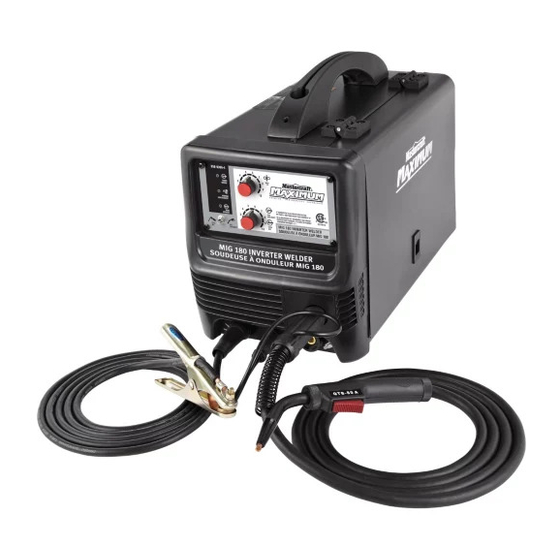
® The Mastercraft Maximum portable and gasless MIG 180 Inverter Welder uses AC single phase 230V, 60 Hz with a 30 A time delayed fuse or circuit breaker. The welder is capable of MIG welding, flux-core welding and DC stick welding. The MIG mode has an infinite voltage control and can weld 24 gauge mild steel to 1/4". -
Page 17: Mode Selector Switch
The welding unit stops working during this period protecting the unit from any damage. The cooling fan of the welding unit continues to work even if the welding unit is shut down by the thermal overload circuit. MIG 180 INVERTER WELDER 058-9306-4... - Page 18 (“+”) terminal. For MIG welding (solid wire) using shielding gas, the MIG gun lead is connected to the positive (“+”) terminal and the ground cable is connected to the negative (“-”) terminal. MC-589306-06 MIG 180 INVERTER WELDER 058-9306-4...
- Page 19 The wire drive compartment has wire feed components such as drive tension adjustment knob (1), drive tension arm (2), drive roll (3), MIG gun securement screw (4), set-up chart (5), polarity terminals (6), and spool hub (7). SPOOL GUN/PISTOLET À BOBINE MIG 180 INVERTER WELDER 058-9306-4...
-
Page 20: Gas Selection
Travel direction: Refers to the direction of the torch moving along the weld joint in relation to the weld puddle. Travel speed: The rate at which the torch is being moved along the weld joint. MIG 180 INVERTER WELDER 058-9306-4... - Page 21 WARN SEMENT WORK INTENS ITÉ 100 150 Gas regulator Ground cable with clamp 8" spool adaptor MIG gun Electrode holder with welding cable MIG consumable kit (nozzle, contact tips, L shaped hexagonal wrench) Gas hose MIG 180 INVERTER WELDER 058-9306-4...
- Page 22 Material name Quantity Illustration Wire spool Electrode Owner’s manual MIG 180 INVERTER WELDER 058-9306-4...
-
Page 23: Assembly Instructions
fig 1B POWE MARCH WARN AVERTIS SEMENT WORK INTENS ITÉ MC-589306-11 3. Attach the electrode (1) to the electrode (fig 1C) holder (2) fig 1C POWE MARCH WARN AVERTIS SEMENT INTENS WORK ITÉ MC-589306-12 MIG 180 INVERTER WELDER 058-9306-4... - Page 24 0589306 GAS INPUT ENTRÊE DE GAZ 220V ~ 240V STICK NORMAL OVER CURRENT GAZ INERTE NORMAL OCV 78Vdc OCV 78Vdc 160 A 140 A 22 V 25.6 V 230 V AC, 30 A max MC-589306-16 MIG 180 INVERTER WELDER 058-9306-4...
- Page 25 0589306 GAS INPUT ENTRÊE DE GAZ 220V ~ 240V STICK NORMAL OVER CURRENT GAZ INERTE NORMAL 160 A 140 A OCV 78Vdc OCV 78Vdc 22 V 25.6 V 230 V AC, 30 A max MC-589306-20 MIG 180 INVERTER WELDER 058-9306-4...
- Page 26 8. Attach the MIG gun (1) and MIG gun trigger cable (2) to their designated fig 1O 100 150 (fig 1O) connections . Refer to Important information page 13. POWE MARC AVERT WARN ISSEM INTEN WORK SITÉ MC-589306-24 MIG 180 INVERTER WELDER 058-9306-4...
- Page 27 Note: The plug of the power cord and the receptacle should adhere to NEMA 6-50 design and the receptacle should be a 230 V, 50 A MARC POWE AVERT WARN ISSEM receptacle. INTEN WORK SITÉ MC-589306-28 MIG 180 INVERTER WELDER 058-9306-4...
- Page 28 Note: If the wire is already installed in the welder, roll the wire back onto the wire spool by manually rotating the wire spool clockwise. Do not allow the wire to come out of rear end MC-589306-31 of the inlet guide tube. MIG 180 INVERTER WELDER 058-9306-4...
- Page 29 Note: When installing the drive roll, the number stamped on the drive roll should face the user. 7. Close the wire drive compartment. MIG 180 INVERTER WELDER 058-9306-4...
-
Page 30: Installing The Wire
3. Remove the wing nut, bushing and washer from the hub in the wire compartment. Note: If a 4" spool is used, proceed to step 4 and then follow step 7. If an 8" spool is used, skip to step 5. MIG 180 INVERTER WELDER 058-9306-4... - Page 31 6. Slide the 8" spool over the adaptor fig 2B MC-589306-37 7. Place the spool on the hub with the wire fig 2C passing from the bottom of the spool into (fig 2C) the drive mechanism MC-589306-38 MIG 180 INVERTER WELDER 058-9306-4...
- Page 32 20. Install the nozzle on the gun assembly, and use anti-spatter spray or gel to keep the spatter from sticking to the inside of the nozzle. 21. Cut off the excess wire that extends past the nozzle leaving 1/4" of the wire to stick out. 22. Turn ON the power switch. MIG 180 INVERTER WELDER 058-9306-4...
- Page 33 (fig 2D) without slipping MC-589306-39 3. Apply slight back pressure against the wire by curling the wire. If wire continues to feed smoothly, the wire tension is set correctly. MIG 180 INVERTER WELDER 058-9306-4...
-
Page 34: Mig Welding Operation
3. Hold the torch in one hand and allow the nozzle to rest on the edge of the work piece farther from the user and at angle A or angle B, depending on the need. MIG 180 INVERTER WELDER 058-9306-4... - Page 35 Use the wire feed control to slightly increase or decrease the heat and penetration by selecting higher or lower wire feed settings. Repeat the above steps 1-5 if a new wire speed, a different diameter wire or a different type of welding wire is selected. MIG 180 INVERTER WELDER 058-9306-4...
-
Page 36: Welding Techniques
Note: For a fixed wire feed speed setting, when the speed is increased, a decrease in MC-589306-43 penetration and a narrowing of the finished weld bead will result. MIG 180 INVERTER WELDER 058-9306-4... - Page 37 The welding operation will make a crackling sound. MC-589306-44 On selection of a small electrode: (fig 2J). • The bead will be high and irregular fig 2J • The arc will be difficult to maintain. MC-589306-45 MIG 180 INVERTER WELDER 058-9306-4...
- Page 38 3. To allow good penetration with minimal spatter, hold the electrode at an angle of 10°–30° between the electrode and the work piece once the initial arc is struck. MIG 180 INVERTER WELDER 058-9306-4...
- Page 39 4. Make sure the arc is accompanied by a crisp cracking sound, as it indicates a proper arc. 5. Move the electrode (1) downwards along desired direction to lay a weld bead (fig 2M). MC-589306-48 MIG 180 INVERTER WELDER 058-9306-4...
- Page 40 The arc will be difficult to maintain. MC-589306-50 Slower weld speed: • The arc will burn through light metals fig 2P • The bead will undercut the work. (fig 2P) • The bead will be flat and porous MC-589306-51 MIG 180 INVERTER WELDER 058-9306-4...
- Page 41 Note: The chipping process not only removes the slag off the weld but also relieves the internal strains developed by the heating and cooling processes of welding. MIG 180 INVERTER WELDER 058-9306-4...
-
Page 42: Welding Positions
MC-589306-55 2. Horizontal position: This position prevents the weld puddle from running downward fig 2U while allowing slow enough travel speed. For this position, angle B should be about (fig 2U) 30 degrees MC-589306-56 MIG 180 INVERTER WELDER 058-9306-4... -
Page 43: Multiple Pass Welding
(fig 2X) joint to close the "V" Weld MC-589306-59 Note: When using self-shielding flux core wire, it is necessary to thoroughly chip and brush the slag off each completed weld bead before making another pass. MIG 180 INVERTER WELDER 058-9306-4... -
Page 44: Spot Welding
The puddle is allowed to fill up the hole leaving a spot weld that is smooth and flush with the surface of (fig 3A) the top piece MC-589306-62 MIG 180 INVERTER WELDER 058-9306-4... - Page 45 5. Make practice spot welds on scrap metal and vary the duration of time of holding the trigger until a desired spot weld is made. 6. Make spot welds on the actual work piece at desired locations. MIG 180 INVERTER WELDER 058-9306-4...
-
Page 46: Maintenance
Store the welder in a clean and dry location away from corrosive gas and excess dust at a temperature of -12°C-48°C (10°F-120°F) and relative humidity of less than 90%. • It is recommended to repack the welder when transporting or storing the welder after use. • Cleaning is required before storage. MIG 180 INVERTER WELDER 058-9306-4... -
Page 47: Troubleshooting
1. Check whether the fuse in power supply is 50 A. breaker. 1. Wrong welding wire or electrode. 1. Use the correct wire or electrode. Arc is hard to start. 2. Base metal is not grounded 2. Make sure the connection is good. properly. MIG 180 INVERTER WELDER 058-9306-4... - Page 48 4. Rusty or corroded wire. 4. Replace the wire. 5. Electrode or damaged flux is too 5. Use correct or undamaged electrode. big. Note: For further assistance on installation and repairs, please contact 1-800-689-9928. MIG 180 INVERTER WELDER 058-9306-4...
- Page 49 MC-589306-65 MIG 180 INVERTER WELDER 058-9306-4...
- Page 50 10 11 22 23 24 25 MC-589306-64 MIG 180 INVERTER WELDER 058-9306-4...
- Page 51 Vertical centre sheet metal Capacitance PCB Connection terminal (red) Heat sink Connection terminal (black) Rectifier Main transformer Middle board Rectifier heat sink Back Panel Reactor assembly Power cord retainer Plastic front panel Power cord Front panel support MIG 180 INVERTER WELDER 058-9306-4...
- Page 52 Description Qty. Description Qty. Circuit breaker Handle Dual gas regulator Main switch Copper nut Gas hose Gas valve connector Fuse board Gas solenoid valve Spool gun function selector switch MIG 180 INVERTER WELDER 058-9306-4...
-
Page 53: Year Limited Warranty
3-Year Limited Warranty This Mastercraft Maximum product is guaranteed for a period of three (3) years from the date of original retail purchase against defects in workmanship and materials. Subject to the conditions and limitations described below, this product, if returned to us with proof of purchase within... -
Page 54: Additional Limitations
This warranty gives you specific legal rights, and you may have other rights, which may vary from province to province. The provisions contained in this warranty are not intended to limit, modify, take away from, disclaim or exclude any statutory warranties set forth in any applicable provincial or federal legislation. MIG 180 INVERTER WELDER 058-9306-4...
Need help?
Do you have a question about the MIG 180 and is the answer not in the manual?
Questions and answers