Table of Contents
Advertisement
Advertisement
Table of Contents

Subscribe to Our Youtube Channel
Related Manuals for MasterCraft MIG 140


Summary of Contents for MasterCraft MIG 140
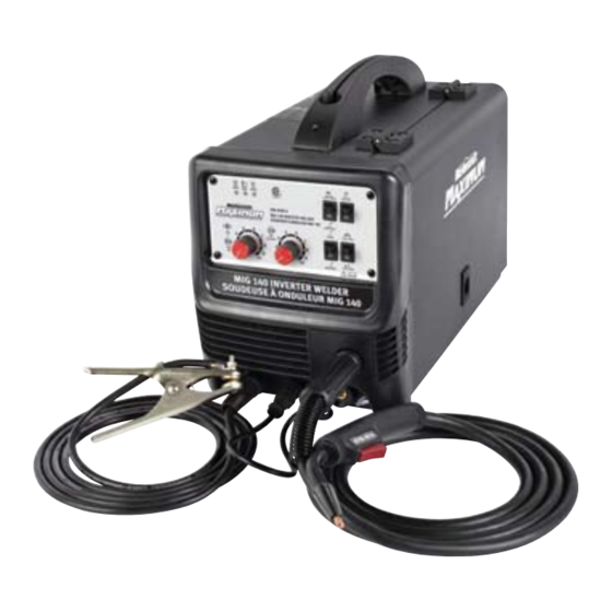
- Page 1 INSTRUCTION MANUAL MIG 140 INVERTER WELDER 058-9305-6...
- Page 2 Keep this instruction manual for future use. Should this product be passed on to a third party, this instruction manual must be included. MIG 140 INVERTER WELDER 058-9305-6...
-
Page 3: Step
Setting the wire tension Press the trigger on the gun. Turn the drive tension adjustment knob (1) clockwise, and increase the drive tension until the wire feeds smoothly without slipping. page 26, steps 1-2 MC-589305-09 MC-589306-12 MIG 140 INVERTER WELDER 058-9305-6... -
Page 4: Stick Welding
STEP 3 Operation Hold the torch in one hand and set the wire speed control with the other hand to its maximum position. Pull the trigger (1) on the torch to start an arc. Drag the torch on the work piece while simultaneously turning the wire speed control counterclockwise. - Page 5 STEP 2 Plug in the power cord. Turn the Spool gun/ MIG selector (1) to the stick welding mode. page 20, step 5-6 MC-589305-09 MC-589306-12 STEP 3 Operation Strike an arc by scratching the work piece (1) with the electrode (2) and raising it by 1/8" and maintain the gap throughout the weld.
-
Page 6: Table Of Contents
QUICK START GUIDE TECHNICAL SPECIFICATIONS 3–4 SAFETY GUIDELINES 5–9 KEY PARTS DIAGRAM 10–11 IMPORTANT INFORMATION 12–18 ASSEMBLY INSTRUCTIONS 19–28 OPERATING INSTRUCTIONS 29–42 MAINTENANCE TROUBLESHOOTING 44–45 MAIN CIRCUIT CHART EXPLODED VIEW PARTS LIST WARRANTY 49–50 MIG 140 INVERTER WELDER 058-9305-6... - Page 7 (1.58 mm) (1.98 mm) ELECTRODE DIAMETER 1/16" , 5/64" 21 39/64 x 12 39/64 x 17 19/64" DIMENSIONS (L x W x H) (55 x 32 x 44 cm) (17.93 kg) WEIGHT 39 lb 8 oz MIG 140 INVERTER WELDER 058-9305-6...
- Page 8 CURRENT SPECIFICATION 10 MINUTES DUTY CYCLE/TIME WELDING CURRENT (IN AMPS) SPOOL GUN (OPTIONAL) SPECIFICATION CONNECTOR 4-pin quick connect power connection MOTOR VOLTAGE 24 V DC WIRE SPEED 590"/min 90 A w/CO RATING 65 A A/Ar gas MIG 140 INVERTER WELDER 058-9305-6...
- Page 9 PERSONAL SAFETY These precautions are intended for the personal safety of the user and others working with the user. Please take time to read and understand them. MIG 140 INVERTER WELDER 058-9305-6...
- Page 10 Do not touch the cylinder with MIG gun and do not weld on the cylinder. Use proper regulators, gas hoses and fittings for the specific application. Use protective cylinder cap whenever possible. MIG 140 INVERTER WELDER 058-9305-6...
- Page 11 10 lens; for above 160 A, use a shade 12 lens. Wear flame retardant clothes, leather shirts, pants or shoes to cover the bare skin from the arc. • Use appropriate shield to prevent other personnel from being affected by harmful rays. MIG 140 INVERTER WELDER 058-9305-6...
- Page 12 Always secure the high pressure cylinder upright to a cart or stationary object. • Do not use a welder to thaw frozen pipes. • Do not look into the valve of the high pressure cylinder when opening it. MIG 140 INVERTER WELDER 058-9305-6...
- Page 13 Note: Recycle the unwanted materials rather than disposing of them as waste. Sort the tools, hoses and packaging in specific categories. Take them to the local recycling center or dispose of them in an environmentally safe way. MIG 140 INVERTER WELDER 058-9305-6...
-
Page 14: Table Of Contents
Power indicator MIG gun connection Thermal overload indicator Electrode cable connection Output current indicator MIG gun trigger connection Spool gun/MIG Selector MIG gun Gas test switch Ground cable with clamp Power cord Grounding cable connection MIG 140 INVERTER WELDER 058-9305-6... - Page 15 Welder back panel POWER PUISSANCE GAS INPUT ENTRÊE DE GAZ MARCHE ARRÊT 110V - 120V MC-589306-03 Description Description Inert gas connection Power switch MIG 140 INVERTER WELDER 058-9305-6...
-
Page 16: Electrode Cable Connection
® The Mastercraft Maximum portable MIG 140 Inverter Welder uses 120 V AC single phase, 60 Hz with a 16 A time delayed fuse or circuit breaker. This welder is ideal to weld carbon steel and stainless steel used in hobby and light duty applications. -
Page 17: Power Switch
The welder will turn off automatically during overload condition. The fan continues to work even if the welder shuts down. When the internal temperature is decreased, this indicator stops glowing indicating that the welder is ready to use. MIG 140 INVERTER WELDER 058-9305-6... -
Page 18: Operation
For MIG welding (solid wire) using shielding gas, the red MIG gun lead is connected to positive (“+”) and the ground cable is MC-589305-03 connected to negative (“-”). Tighten the leads using the fasteners. MIG 140 INVERTER WELDER 058-9305-6... -
Page 19: Gas Selection
Travel direction Refers to the direction of the torch moving along the weld joint in relation to the weld puddle. Travel speed The rate at which the torch is being moved along the weld joint. MIG 140 INVERTER WELDER 058-9305-6... - Page 20 Wire drive compartment The wire drive compartment has wire feed components such as wire spool (1), polarity terminals (2), drive tension adjusting knob (3), drive tension arm (4), drive roll (5), and a set up chart (6). MIG 140 INVERTER WELDER 058-9305-6...
- Page 21 Packaging content list Material name Quantity Illustration MIG/stick welder 100 150 Gas regulator Ground cable with clamp Gas hose (3 m) MIG gun Electrode holder with welding cable MIG nozzle MIG 140 INVERTER WELDER 058-9305-6...
- Page 22 Material name Quantity Illustration Wire spool with gas shielded welding wire (0.45 kg) Contact tip (0.030") Hexagonal wrench Electrode Owner’s manual MIG 140 INVERTER WELDER 058-9305-6...
-
Page 23: Assembly Instructions
1. Plug the ground cable (1) into the ground cable connection (2) of the fig A (fig A). welder (3) MC-589305-04 2. Plug the electrode holder cable (1) into the electrode cable connection (2) fig B (fig B) MC-589305-05 MIG 140 INVERTER WELDER 058-9305-6... - Page 24 Note: The plug of the power cord and the receptacle should adhere to NEMA 6-50 design MC-589305-08 6. Switch the MIG/stick selector (1) to the (fig F) stick welding mode fig F MC-589305-09 MIG 140 INVERTER WELDER 058-9305-6...
- Page 25 Note: If the wire is already installed in the welder, roll the wire back onto the wire spool by manually rotating the wire spool clockwise. Do not allow the wire to come out of rear end MC-589305-12 of the inlet guide tube. MIG 140 INVERTER WELDER 058-9305-6...
- Page 26 Note: When installing the drive roll, the number stamped on the drive roll should face the user. 7. Close the wire drive compartment. MIG 140 INVERTER WELDER 058-9305-6...
- Page 27 MIG welding 0.023"- 0.035" MIG wire Flux-core welding 0.030"- 0.035" flux-core wire Note: MIG wire can be either mild steel, stainless steel, or aluminium solid wire. Note: This welder cannot weld metals thinner than 24 gauge. MIG 140 INVERTER WELDER 058-9305-6...
- Page 28 The adjustment knob is designed to adjust the pressure tension of the wire spool. MC-589305-16 4. Place the spool on the hub with the wire fig N passing from the bottom of spool into (fig N) the drive mechanism MC-589305-17 MIG 140 INVERTER WELDER 058-9305-6...
- Page 29 20. Install the nozzle on the gun assembly, and use anti-spatter spray or gel to keep the spatter from sticking to the inside of the nozzle. 21. Cut off the excess wire that extends past the nozzle leaving 1/4" of the wire to stick out. 22. Turn the power switch ON. MIG 140 INVERTER WELDER 058-9305-6...
- Page 30 Do not touch the cylinder with MIG gun. Do not weld on the cylinder. • Always secure the cylinder upright to a cart or stationary object. • Keep the cylinder away from welding or electrical circuits. • Use proper regulators, gas hose and fittings. MIG 140 INVERTER WELDER 058-9305-6...
- Page 31 4. Attach the other end of the gas hose (1) to the inert gas connection (2) on fig S 100 150 (fig S) the back panel of the welder POWER PUISSANCE GAS INPUT ENTRÊE DE GAZ MARCHE ARRÊT 110V - 120V MC-589305-22 MIG 140 INVERTER WELDER 058-9305-6...
- Page 32 2. Make sure the ground connection at the clamp is proper. A poor connection at the clamp will reduce welding power and heat. 3. Make sure the ground clamp touches the metal. MIG 140 INVERTER WELDER 058-9305-6...
- Page 33 If puddle and to direct the force of the arc (fig W) angle A is increased, penetration will increase, and if it is decreased penetration (fig V) will decrease MIG 140 INVERTER WELDER 058-9305-6...
-
Page 34: Operating Instructions
3. Hold the torch in one hand, and allow the nozzle to rest on the edge of the work piece farther from the user and at angle A or angle B. Refer operating instructions page 28. MIG 140 INVERTER WELDER 058-9305-6... - Page 35 Repeat the above steps 1-6 if a new heat setting, a different diameter wire, or a different type of welding wire is selected. MIG 140 INVERTER WELDER 058-9305-6...
-
Page 36: Welding Techniques
Note: For a fixed heat setting, when the speed is increased, a decrease in penetration and a MC-589305-28 narrowing of the finished weld bead will result. MIG 140 INVERTER WELDER 058-9305-6... -
Page 37: Welding Positions
For this position, the torch nozzle should be kept at an angle of 30 degrees with respect to the (fig c) work piece MC-589305-34 MIG 140 INVERTER WELDER 058-9305-6... - Page 38 2. Set higher amperage for thick and heavy metals. 3. Try the intended weld on scrap metal to ensure the proper determination of the type of electrode and the amperage. MIG 140 INVERTER WELDER 058-9305-6...
- Page 39 The rod may stick to work piece Note: Rate of travel over the work piece also affects the weld. To ensure proper penetration and enough rod deposit, the arc must be moved slowly and evenly along the weld seam. MC-589305-37 MIG 140 INVERTER WELDER 058-9305-6...
- Page 40 (2) when striking the initial arc (fig i) MC-589305-38 3. To allow good penetration with minimal spatter, hold the electrode at an angle of 10-30between the electrode and the work piece once the initial arc is struck MIG 140 INVERTER WELDER 058-9305-6...
- Page 41 4. Make sure the arc is accompanied by a crisp cracking sound, as it indicates a proper arc. 5. Move the electrode (1) downwards along fig k required direction to lay a weld bead (fig k). MC-589305-40 MIG 140 INVERTER WELDER 058-9305-6...
- Page 42 The ridges in the weld are long and triangular. MC-589305-43 Slower weld speed: (fig o) • The bead will be wide and tall fig o • This results in the occurrence of cold joints and slag inclusions. MC-589305-44 MIG 140 INVERTER WELDER 058-9305-6...
- Page 43 Potential hazard that could result in serious injury or loss of life. • Do not perform any welding while standing, kneeling or lying on the grounded area. Failure to comply could result in electric shock. MIG 140 INVERTER WELDER 058-9305-6...
-
Page 44: Welding Position
In this position the electrode and arc force is directed more toward the metal above MC-589305-48 (fig s) the weld joint MIG 140 INVERTER WELDER 058-9305-6... -
Page 45: Multiple Pass Welding
MC-589305-51 (fig v) a spot weld Note: Do not use 0.030" self-shielding flux core wires when using this method unless the metal is very thin or excessive filler metal and minimal penetration is acceptable. MIG 140 INVERTER WELDER 058-9305-6... - Page 46 5. Make practice spot welds on scrap metal and vary the duration of time of holding the trigger until a desired spot weld is made. 6. Make spot welds on the actual work piece at desired locations. MIG 140 INVERTER WELDER 058-9305-6...
-
Page 47: Maintenance
120 °F and relative humidity of less than 90%. • It is recommended to repack the welder when transporting or storing the welder. • Before storage, clean the welder and its accessories and seal the plastic bag containing the accessories. MIG 140 INVERTER WELDER 058-9305-6... -
Page 48: Troubleshooting
1. Replace the switch. Cooling fan is turning very slowly or does 2. The cooling fan is broken. 2. Replace or repair the fan. not work. 3. Wire connection is not proper. 3. Check the wire connection. MIG 140 INVERTER WELDER 058-9305-6... - Page 49 2. Check the gas system. not flow. 3. The gas system rubber pipe is 3. Connect the gas system and bind it firmly. damaged or broken. Note: For further assistance on installation and repairs, please contact 1-800-689-9928. MIG 140 INVERTER WELDER 058-9305-6...
- Page 50 2 FAN MC-589305-56 MIG 140 INVERTER WELDER 058-9305-6...
- Page 51 12 13 17 18 MC-589305-57 MIG 140 INVERTER WELDER 058-9305-6...
- Page 52 Base pads Wire spool cover Case base Wire spool adjust nut Main PC board Insulated connector Front panel Back panel Front panel control board Power cord Front panel support Main switch Nozzle Gas solenoid valve MIG 140 INVERTER WELDER 058-9305-6...
-
Page 53: Warranty
3-Year Limited Warranty This Mastercraft Maximum product is guaranteed for a period of 3 years from the date of original retail purchase against defects in workmanship and materials. Subject to the conditions and limitations described below, this product, if returned to us with proof of purchase within... - Page 54 This warranty gives you specific legal rights, and you may have other rights, which may vary from province to province. The provisions contained in this warranty are not intended to limit, modify, take away from, disclaim, or exclude any statutory warranties set forth in any applicable provincial or federal legislation. MIG 140 INVERTER WELDER 058-9305-6...
Need help?
Do you have a question about the MIG 140 and is the answer not in the manual?
Questions and answers