
Related Manuals for ACTi E924


Summary of Contents for ACTi E924
- Page 1 Outdoor Mini Dome & Outdoor Mini Fisheye Dome Hardware Manual E924, E925, E926, E927, E928, E929 E924M, E925M, E926M, E927M, E928M, E929M Ver. 2015/04/17...
-
Page 2: Table Of Contents
List of Models ..................7 Package Contents ................9 Physical Description ..............10 E924 / E926 / E928 ..............10 E925 / E927 / E929 ..............10 E924M / E926M / E928M ............. 12 E925M / E927M / E929M ............. 12 Mounting Options ................ - Page 3 How to Replace the Dome Cover ........... 30 Accessing the Camera Configure the IP Addresses ............34 Using DHCP Server to Assign IP Addresses ........ 34 Using the Default Camera IP Address .......... 36 Access the Camera ................. 38 www.acti.com...
-
Page 4: Precautions
Every reasonable care has been taken during the writing of this manual. Please inform your local office if you find any inaccuracies or omissions. We cannot be held responsible for any typographical or technical errors and reserve the right to make changes to the product and manuals without prior notice. www.acti.com... - Page 5 This product has been tested and found to comply with the limits for Class B Information Technology Equipment according to European Standard EN 55022 and EN 55024. In a domestic environment, this product may cause radio interference in which cause the user may be required to take adequate measures. www.acti.com...
-
Page 6: Safety Instructions
Safety Check Upon completion of any service or repairs to this video product, ask the service technician to perform safety checks to determine if the video product is in proper operating condition. www.acti.com... -
Page 7: Introduction
Hardware Manual Introduction List of Models This hardware manual contains the following models: 5MP Outdoor Mini Dome with D/N, Adaptive IR, Basic WDR, Fixed E924 lens 5MP Outdoor Mini Dome with D/N, Adaptive IR, Basic WDR, E924M M12 connector, Fixed lens... - Page 8 E929 WDR, Fixed lens 3MP Outdoor Mini Fisheye Dome with D/N, Adaptive IR, Superior E929M WDR, M12 connector, Fixed lens From the installation perspective, the above models are very similar; therefore one manual is used for all of them. www.acti.com...
-
Page 9: Package Contents
Hardware Manual Package Contents Check if the camera package comes with the following items: Camera Camera Screw Kit (E924, E924M, E926, E926M, (E925, E925M, E927, E927M, E928, E928M) E929, E929M) Extra Desiccant Bag Drill Template Hexagon Screwdriver Drill Template Cosmetic Cover... -
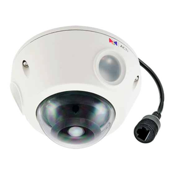
Page 10: Physical Description
Hardware Manual Physical Description E924 / E926 / E928 E925 / E927 / E929 www.acti.com... - Page 11 Connects to audio input devices, such as a microphone with built-in amplifier, etc. See How to Connect Audio In Device page 29 for more information. NOTE: The microphone must have a built-in amplifier. Connecting an ordinary microphone will dwarf sounds and will result in inaudible recording. www.acti.com...
-
Page 12: E924M / E926M / E928M
Hardware Manual E924M / E926M / E928M E925M / E927M / E929M www.acti.com... - Page 13 Connects to audio input devices, such as a microphone with built-in amplifier, etc. See How to Connect Audio In Device on page 29 for more information. NOTE: The microphone must have a built-in amplifier. Connecting an ordinary microphone will dwarf sounds and will result in inaudible recording. www.acti.com...
-
Page 14: Mounting Options
(optional accessory set) is required for this type of installation. NOTE: For more information about the mounting solutions and accessories, please check the Mounting Accessory Selector in our website (http://www.acti.com/mountingselector). The above mounting accessories are not included in the package. Contact your sales agents to purchase. www.acti.com... -
Page 15: Installation Procedures
2. Depending on the material of the surface where the camera will be installed, it may be necessary to drill the three (3) screw holes and use the supplied screw tox. In this case, attach the bundled drill template on the surface and drill the screw holes. www.acti.com... -
Page 16: Step 2: Open The Dome Cover
An extra bag is bundled with the camera that can be used for replacement, as needed, over time. The photographed model in this section is for demonstration only. The instruction applies to all models listed in this manual. www.acti.com... -
Page 17: Step 3: Route The Cables
3. Push the cable through the hole on the surface. If the cable will be routed along the surface 1. Pull the rubber tab off from the base of the camera. 2. Route the camera cable through this gap. www.acti.com... -
Page 18: Step 4: Install The Camera
2. Install the camera to the surface using the three (3) bundled screws. NOTE: Please make sure the screw is flat on the plate. The photographed model in this section is for demonstration only. The instruction applies to all models listed in this manual. www.acti.com... -
Page 19: Step 5: Waterproof The Cable Connection
RJ-45 or M12 connector. M12 Ethernet Cable (for E9xxM models only) Typical M12 Ethernet cable has waterproof connection. Simply connect and screw the cable connectors to make the connection waterproof. Make sure the connectors are secured tightly. www.acti.com... -
Page 20: Ethernet Cable (For E9Xx Models Only)
1. Detach the cable gland as shown below. Gland Body Clamping Nut Sealing Rubber and Claw 2. On the network side cable, insert the clamping nut through the Ethernet cable. 3. Insert the sealing rubber and claw through the Ethernet cable. www.acti.com... - Page 21 5. Attach the gland body to the Ethernet port of the camera. IMPORTANT! Make sure the rubber ring is completely aligned and flat on the gland body to avoid possible water leakage. 6. Connect the RJ-45 connector of the network cable to the Ethernet port of the camera. www.acti.com...
- Page 22 8. Attach the clamping nut to the cable gland body. Make sure the clamping nut is tightly secured and the rubber is squeezed in to avoid water leakage. DISCLAIMER: ACTi will not be responsible for camera damage caused by water entering the cable connections. www.acti.com...
-
Page 23: Step 6: Connect To Network
Power Cable PoE Switch Ethernet Cable AC Power (Data + Power) Source Camera Step 7: Access the Camera Live View Accessing the Camera on page 34 for more information on how to access the Live View of the camera. www.acti.com... -
Page 24: Step 8: Close The Dome Cover
2. Tighten the three (3) screws using the supplied hex screwdriver to attach the dome cover. 3. Remove the thin film. Final installation should look similar to the illustration below. NOTE: The photographed model in this section is for demonstration only. The instruction applies to all models listed in this manual. www.acti.com... -
Page 25: Other Adjustments And Accessories
In case there is a need to remove the card, make sure to access the camera Web Configurator to safely “unmount” the card first (see the camera Firmware User’s Manual for more information). Once unmounted from the firmware, push the card to eject it from the slot. www.acti.com... -
Page 26: How To Adjust The Viewing Angle And Orientation
This section describes the procedures in adjusting the viewing angle and pan direction of the camera. Camer Parts Overview NOTE: Tilt Adjustment Screws are available on Mini Dome cameras only. 1. Open the dome cover. 2. Loosen the three (3) pan adjustment screws. www.acti.com... - Page 27 For mini fisheye dome cameras, the ridge indicates the top side orientation. 4. Once done, tighten the three (3) screws to fix the lens position. For Mini Fisheye dome cameras, skip to Step 7. 5. For Mini Dome cameras, loosen the two (2) tilt adjustment screws. www.acti.com...
- Page 28 Hardware Manual 6. Adjust the tilt and tighten back the screws to fix the tilt position. 7. Close the dome cover. www.acti.com...
-
Page 29: How To Connect Audio In Device
3. If the camera is installed outdoors, be sure to wrap the audio connectors with Waterproof Tape (can be purchased in hardware stores). DISCLAIMER: ACTi will not be responsible for camera damage due by water leakage caused by improper waterproofing of cables. www.acti.com... -
Page 30: How To Replace The Dome Cover
To replace the dome cover, follow the procedures below: 1. Open the dome cover. 2. Detach the screw securing the cover to the camera module. 3. Remove the four (4) screws securing the dome cover bracket. 4. Remove the bracket and then the transparent dome cover. www.acti.com... - Page 31 6. Align and place the rubber on the dome cover housing with the arrow pointing towards the camera logo. Note that the side of the rubber with 3 lines should face the housing while the side with 2 lines should face the camera module. Camera logo here Dome Cover Housing Side Camera Module Side www.acti.com...
- Page 32 8. Align and place the dome cover bracket on the housing with the arrow pointing towards the camera logo. Tightly attach the four (4) screws to secure the dome cover bracket to the housing. Camera logo here 9. Attach the screw to secure the dome cover housing to the camera module. www.acti.com...
- Page 33 Hardware Manual 10. Close the dome cover. www.acti.com...
-
Page 34: Accessing The Camera
Windows system – just by pressing the “Network” icon, all the cameras of the local area network will be discovered by Windows thanks to the UPnP function support of our cameras. In the example below, we successfully found the camera that we had just connected to the network. www.acti.com... - Page 35 The IP Utility can be downloaded for free from http://www.acti.com/IP_Utility With just one click, you can launch the IP Utility and there will be an instant report as follows: You can quickly see the camera model in the list. Click on the IP address to automatically launch the default browser of the PC with the IP address of the target camera filled in the address bar of the browser already.
-
Page 36: Using The Default Camera Ip Address
PC has to be configured to match the network segment of the camera. Manually adjust the IP address of the PC: In the following example, based on Windows 7, we will configure the IP address to 192.168.0.99 and set Subnet Mask to 255.255.255.0 by using the steps below: www.acti.com... - Page 37 In such case, please plug in only one camera at a time, and change its IP address by using the Web browser before plugging in the next one. This way, the Web browser will not be confused about two devices having the same IP address at the same time. www.acti.com...
-
Page 38: Access The Camera
When using Internet Explorer browser, the ActiveX control for video stream management will be downloaded from the camera directly – the user just has to accept the use of such control when prompted so. No other third party utilities are required to be installed in such case. www.acti.com... - Page 39 HTTP port of the camera is 80, which can be omitted from the address for convenience. Before logging in, you need to know the factory default Account and Password of the camera. Account: Admin Password: 123456 www.acti.com...
- Page 40 Copyright © 2015, ACTi Corporation All Rights Reserved 7F, No. 1, Alley 20, Lane 407, Sec. 2, Ti-Ding Blvd., Neihu District, Taipei, Taiwan 114, R.O.C. TEL : +886-2-2656-2588 FAX : +886-2-2656-2599 Email: sales@acti.com...
Need help?
Do you have a question about the E924 and is the answer not in the manual?
Questions and answers