Table of Contents
Advertisement
Quick Links
Advertisement
Table of Contents

Related Manuals for XtendLan DPC-D247


Summary of Contents for XtendLan DPC-D247
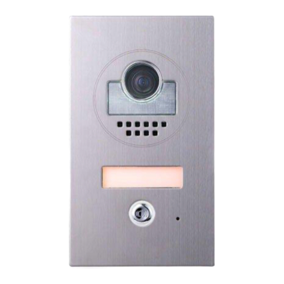
- Page 1 DPC-D247 2-wired door station User´s manual...
-
Page 2: Parts And Function
Introduction The door station is designed with high resolution color CCD camera, it pro- vides wide angle of 105 for DT 2-wire intercom system. The high white LED for night view makes the door station working efficiently at night. The front panel is made of medical stainless steel with a thickness of 2.5 mm for better protection against vandalism and cauterization. -
Page 3: Door Station Mounting
Lock Control Jumper: To select the lock type. Door Station Code DIP: Total 4 door stations can be supported. T/R+,T/R-: USB-RS485 communication terminal. Main Connect Port: To connect the bus line and the electronic locks. BUS: Connect to the bus line, non-polarity. PL: External lock power input, connect to the power positive(power +). -
Page 4: Placing Name Label
Placing Name Label Steps: 1. Use the special spanner to move 90 to loosen the screw. 2. Open the front panel. 3. Insert the name plate System Wiring and Connections Basic one-to-one Connection monitor L1 L2 PL S1+ S2+ S-... -
Page 5: Electric Lock Connection
Electric Lock Connection Door Lock Controlled with Internal Power Note: 1. Electronic lock of Power-on-to-unlock type should be used. 2. The door lock is limited to 12V, and holding current must be less than 250mA. 3. The door lock control is not timed from Exit Button(EB). 4. -
Page 6: Unlock Parameter Setting(Set On Monitor)
connect one lock connect two locks Take off the Jumper Take off the Jumper POWER POWER SUPPLY SUPPLY LOCK LOCK LOCK 5.2.3 Unlock parameter setting(set on monitor) H/W : a1.3 S/W: V17.11.418.00 Manual Monitor Intercom Multimedia Local addr: Monitor Unlock timing: Video standard: UI-CODE: Close... -
Page 7: Dip Switches Setting
DIP Switches Setting The DIP switch is designed to set the code ON(1) OFF(0) for door station and monitor, there are two states for each DIP switch, please refer to the sketch map. Door station DIP setting Total 2 bits can be configured, bit-1 and bit-2 are used to assign ID code for door sta- tion.The switches can be modified either before or after installation. -
Page 8: Specification
Bit state User code Bit state User code Bit state User code code=0 code=6 code=11 3 4 5 3 4 5 3 4 5 code=1 code=7 code=12 3 4 5 3 4 5 3 4 5 code=2 code=8 code=13 3 4 5 3 4 5 3 4 5 code=3...
Need help?
Do you have a question about the DPC-D247 and is the answer not in the manual?
Questions and answers