
Subscribe to Our Youtube Channel
Related Manuals for XtendLan DPC-D248-R


Summary of Contents for XtendLan DPC-D248-R
- Page 1 English 2-Wire Video Outdoor Station User Manual RF CARD RF CARD DPC-D248-R DPC-D248-FR...
-
Page 2: Table Of Contents
Contents 1.Parts and Functions..................... 1 2.Terminal Descriptions ..................1 3.Door Station Mounting ..................2 4. System Wiring and Electric Lock Connection ............. 4 5. ID Card Registration ................... 8 6.Unlock Operations ....................10 7.ID Setting of Door Station ..................10 8. -
Page 3: Parts And Functions
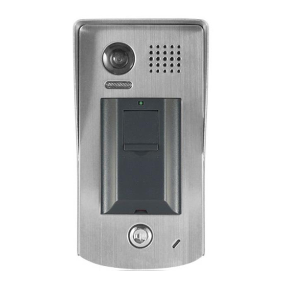
1.Parts and Functions Camera Lens Speaker Night Light ID card window RF CARD RF CARD 30 mm Nameplate Call Button Rainy Cover Microphone 93 mm Camera Lens Speaker Night Light ID card window RF CARD RF CARD Nameplate Call Button Microphone Screws for panel mounting... -
Page 4: Door Station Mounting
• Lock Control Jumper: To select the lock type. • Main Connect Port: To connect the bus line and the electronic locks. • BUS: Connect to the bus line, no polarity. • PL: External lock power input, connect to the power positive(power +). •... -
Page 5: Placing Name Label
Mounting Drill a hole in the wall to match the size of the Connect the cable correctly mounting box and attach to the wall. Attach the panel to the mounting box and use screws supplied to fix the panel Placing Name Label Use a screwdriver to unscrew the screw, and cock the host , then Placing Name Label. -
Page 6: Basic Connection
4. System Wiring and Electric Lock Connection Basic Connection monitor L1 L2 PL S+ S- Electric Lock Connection Door Lock Controlled with Internal Power Note: Electronic lock of Power-on-to-unlock type 1 2 3 should be used. Jumper position in 2-3 The door lock is limited to 12V, and holding current must be less than 250mA. -
Page 7: Door Lock Controlled With Dry Contact
Door Lock Controlled with Dry Contact Note: The external power supply must be used according to the lock. Take off the Jumper The inside relay contact is restricted to AC or DC 24V/1A. The jumper must be taken off before connecting. Setup the Unlock Mode of Monitor for different lock types. -
Page 8: Multi Door Stations Connection
Multi Door Stations Connection 4# Camera 3# Camera 2# Camera 1# Camera (Device Address:3) (Device Address:2) (Device Address:1) (Device Address:0) monitors DIP=on,off,off A B C D DBC4S DT-DPS 85~260VAC Impedance switch Multi Monitors Connection Basic IN-OUT Wiring Mode 3 4 5 6 3 4 5 6 3 4 5 6 3 4 5 6... - Page 9 With DBC4S Wiring Mode monitor monitor 3 4 5 6 3 4 5 6 Impedance Code=14, DIP-6=on Code=15, DIP-6=on OFF ON switch DIP=on,off,off monitor monitor 3 4 5 6 3 4 5 6 Code=12, DIP-6=on Code=13, DIP-6=on monitor monitor 3 4 5 6 3 4 5 6 Code=3, DIP-6=on Code=2, DIP-6=on...
-
Page 10: Id Card Registration
5. ID Card Registration Introduction: • Up to 320 user cards can be registered by the door station. • Easy management with LED status and sound hints. • There are two master cards, one card and one MASTER CARD ADD MASTER card, When registered new master cards, the old master cards CARD DELETE... - Page 11 Access Initialization (delete all user cards): Show the Show the Show the MASTER CARD MASTER CARD MASTER CARD card to ID card card to ID card window. card to ID card window DELETE window in standby mode. again,format operation is (At this time show the MASTER CARD it will return to the "Delete User...
-
Page 12: Unlock Operations
6.Unlock Operations Unlocking of ID Card When the registered user card has been shown to ID card window, the LED background indicator lights up, the buzzer sounds,and the electric door strike is unlocked. 1. If show the authorized user card,the buzzer will sound of beep+,and the LED background indicator will light up. -
Page 13: Precaustions
Pinhole Sharp Color CCD; 420 TV Lines; • Lock Power supply: 12Vdc, 280mA(Internal Power); • Number of relay circuits: 2(the second lock need external device to support) • Mounting: Surface mounting DPC-D248-R Flush mounting DPC-D248-FR • Working temperature: -10ºC ~ +45ºC • Wiring: 2 wires,non-polarity •... -
Page 14: Cables Requirements
10. Cables Requirements The maximum distance of the wiring is limited in the DT system. Using different cables may also affect the maximum distance which the system can reach. The farest monitor monitor with two or four monitors monitor monitor DBC/DBC-4 When Monitor quantity <...
Need help?
Do you have a question about the DPC-D248-R and is the answer not in the manual?
Questions and answers