Table of Contents
Advertisement
Quick Links
Advertisement
Table of Contents

Related Manuals for XtendLan DPC-D244-K


Summary of Contents for XtendLan DPC-D244-K
- Page 1 2 -Wire Intercom System DPC-D244-K User's manual...
-
Page 2: Parts And Functions
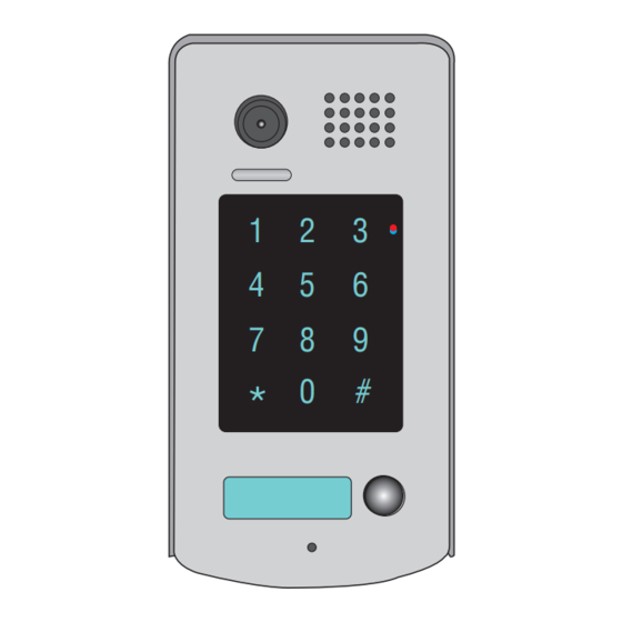
1.Parts and Functions Camera Lens Speaker Touch Sensitive Digital Keypad 23 mm Nameplate Call Button Microphone Rainy Cover 90 mm 2.Terminal Descriptions Lock Control Jumper Doorstation Code DIP MIC adjustment SPK adjustment Main Connect Port S 2 + S - P L S 1 + B U S... -
Page 3: Door Station Mounting
• • Lock Control Jumper: To•select•the•lock•type:•see•section•5 • • Doorstation Code DIP: Total•4•door•stations•can•be•supported,see•section•6 • • MIC:•Adjust•the•volume•of•Microphone • • SPK:•Adjust•the•volume•of•Speaker • • Main Connect Port:•To•connect•the•bus•line•and•the•electronic•locks. • • BUS:•Connect•to•the•bus•line,•no•polarity. • • PL:•External•lock•power•input,•connect•to•the•power•positive(power•+). • • S1+,•S2+:•Lock•power(+)•output,•to•connect•2•locks. • • S-:•Lock•power(-)•output,•connect•to•the•power(-)•input•of•locks(only•when•using•the•camera•to• power•the•locks,•if•using•the•external•power•supply•for•the•locks,•the•S-•will•not•be•connected). 4.Door Station Mounting adjust camera angle Drill holes in the wall to match the size of Connect the cable correctly and adjust screws and attach the rainy cover to the wall. -
Page 4: Placing Name Label
Placing Name Label Move•the•plastic•cover•away•to•open•the•transparent•name•label•cover,••insert•a•name•paper,•then•put• the•plastic•cover•back•to•the•panel.• Adjusting Camera Angle use•a•screwdriver•to•loosen•the•screw•and•adjust•the• angle•for•the•camera•,then•fix•the•screw. -
Page 5: System Wiring And Connections
5.System Wiring and Connections Basic Connection monitor L1 L2 PL S1+ S2+ S- Electric Lock Connection Door Lock Controlled with Internal Power •••••Note: 1.• Electronic•lock•of•Power-on-to-unlock•type•should•be•used. 2.• The•door•lock•is•limited•to•12V,•and•holding•current•must•be•less•than•250mA. 3.• The•door•lock•control•is•not•timed•from•Exit•Button(EB). 4.• The•Unlock Mode•Parameter•of•Monitor•must•be•set•to•0•(by•default). 1 2 3 1 2 3 Connect one lock Connect two locks Jumper position in Jumper position in... -
Page 6: Electromagnetic Lock Connection
Electromagnetic Lock Connection Door Lock Controlled with Internal Power •••••Note: 1.• Electromagnetic•lock•of•Power-off-to-unlock•type•should•be•used. 2.• The•door•lock•is•limited•to•12V,•and•holding•current•must•be•less•than•250mA. 3.• The•door•lock•control•is•not•timed•from•Exit•Button(EB). 4.• The•Unlock Mode•Parameter•of•Monitor•must•be•set•to•1•(by•default). 1 2 3 1 2 3 Connect one lock Connect two locks Jumper position in Jumper position in LOCK Normally closed LOCK LOCK Door Lock Controlled with Dry Contact... -
Page 7: Unlock Parameter Setting(Set In Monitor)
connect•one•lock connect•two•locks Take off the Jumper Take off the Jumper POWER POWER SUPPLY SUPPLY LOCK LOCK LOCK Unlock parameter setting(set in monitor) Outdoor Tone -- 01 monitor Intercom Tone -- 05 Monitor Time -- 1min * * * Password: intercom Advanced Set... -
Page 8: Multi Door Stations Connection
Multi Door Stations Connection monitors DBC4 A B C D 85~260VAC 4# Camera 3# Camera 2# Camera 1# Camera ID=11 ID=01 ID=00 ID=10 1 2 3 4 1 2 3 4 1 2 3 4 1 2 3 4 L1 L2 PL S1+ S2+ S- L1 L2 PL S1+ S2+ S- L1 L2 PL S1+ S2+ S- L1 L2 PL S1+ S2+ S-... -
Page 9: Multi Monitors Connection
Multi Monitors Connection Basic IN-OUT Wiring Mode monitor 3 4 5 6 Code=15, DIP-6=on monitor 3 4 5 6 Code=14, DIP-6=off monitor 3 4 5 6 Code=0, DIP-6=off 85~260AC ID=00 1 2 3 4... -
Page 10: Dip Switches Settings Of Door Station
6.DIP Switches Setting ON(1) OFF(0) DIP Switches Settings of Door Station Total•4•bits•on•the•DIP•switches•can•be•configured.The•switches•can•be•modified•either•before•or•after•installation. Setting Item Bit state Descriptions Default•setting,•ID•=•0(00),•set•to•the•first•Door•Station. 1 2 34 ID•=•1(10),•set•to•the•second•Door•Station. Bit1•and•Bit2 1 2 34 (it•is•used•to•set•the•ID• ID•=•2(01),•set•to•the•third•Door•Station. code•for•door•station) 1 2 34 ID•=•3(11),•set•to•the•fourth•Door•Station. 1 2 34 Activate•external•output•setting,the•relay•2•terminal•doesn't• respond•the•second•lock•and•will•be•closed•for•60•seconds• when•the•"Lockout"•is•carried•out.The•alarm•connected•to•the• Bit3 terminal•of•relay•2•will•be•activated Not•activate Reserve... -
Page 11: Functions Setting Up
Bit-1•to•Bit-5•are•used•to•User•Code•setting.The•DT596•responds•to•0~15•. Bit state User Code Bit state User Code Bit state User Code Code=0 Code=6 Code=11 3 4 5 3 4 5 3 4 5 Code=1 Code=7 Code=12 3 4 5 3 4 5 3 4 5 Code=2 Code=8 Code=13 3 4 5 3 4 5 3 4 5... - Page 12 Order Setting items Setting range Default value Setting code Reset•all•settings 1,2,3,4 1•~•12•digits Setting•the•master•code 1,2,3,4 Valid•keys:0•~•9 Setting•the•key 10•to•99•seconds/ 10•seconds illumination•time continually•lit Setting•the•unlock•time 01•to•99•seconds 1•seconds Setting•the•unlock•mode •0:opened/1:closed opened Operation•tone•settings 0:on/1:off Reset•code•settings 1,2,3,4 &#•function•settings 0:Normal/1:Reverse Normal Call•tone•settings 0:Enable/1:Disable Enable Interference•resistant•• Valid•keys:0•~•5 grade•settings Reserve Reserve Reserve 10~17...
- Page 13 blue Each•operation•is•indicated•by•the•lighting•up•of•the•LED• indicators• on• the• right• section• of• the• unit,• and• by• the• sounding•of•the•buzzer. (red) (blue) Input the master code. (Default: [ ] +[#] ) Beep+, Beep 1.Reset all settings 2.Setting the master code 3.Setting the key 4.Setting the illumination time unlock time (Default 1234) (Default 10s)
- Page 14 (red) (blue) Input the master code. (Default: [ ] +[#]) Beep+, Beep 5.Setting the unlock mode 6.Setting operation tone 7.Reset code setting 8. &# function setting (Default 0(opened)) (Default ON) (Default Normal) Input the setting code. Input the setting code. Input the setting code.
- Page 15 (red) (blue) Input the master code. (Default: [ ] +[#]) Beep+, Beep 9. Call tone setting 10.Interference resistant grade setting (Default enable) (Default 2) Input the setting code. Input the setting code. 08+# 09+# (red) (blue) (red) (blue) Beep+, Beep Beep+, Beep Inputting of code (ex.: 1) Inputting of code (ex.: 3)
- Page 16 (red) (blue) Input the master code. (Default: [ ]+[#] ) Beep+, Beep 12.Setting the code 13.Setting the code 14.Setting the code 15.Setting the code forTemporary1 forTemporary2 for user group1 for user group2 20~59 60~99 Input the setting code. Input the setting code. Input the setting code.
-
Page 17: Unlock Operations
8.Unlock Operations Unlocking of user code When•the•registered•user•code•has•been•input•using•the•keypad•(1~12•digits),•the•LED•indicator•(group 1:•red,•group•2:•blue)•lights•up,•the•buzzer•sounds,and•the•electric•door•strike•is•unlocked. Example:group•1 Example:group•2 ••••••••••••••2011 ••••••••••••••2012 Red LED lights up Blue LED lights up (during relay1 operation) (during relay2 operation) (red) (blue) (red) (blue) Beep+ Beep+ • • The•time•interval•during•which•the•button•must•be•pressed•is•approximately•10•seconds.•If•the• time•interval•exceeds•approximately•10•seconds,•the•input•value•will•be•cleared. • • If•you•make•a•mistake•when•inputting•the•user•code,press•the"•cancel"•button•and•input•the•user• code•again. •... -
Page 18: Power Supply Instructions
9.Power Supply Instructions Name Discription Usage Power•supply,85~260Vac•input,24Vdc/3A• Connect•with•multi•doorstations•or• PS5-24V output,10•DIN•modules multi•monitors(up•to•2•or•above) Power•supply,85~260Vac•input,24Vdc/1A• Connect•with•one•doorstation•and•one• PS4-24V output,for•basic•kit•only,4•DIN•modules monitor(DT16••can••be•connected•two) 10. Precaustions • • Please•clean•the•unit•with•soft•cotton•cloth,•don't•use•the•organic•impregnant•or•chemical•clean•agent.•If• necessary,•please•use•a•little•pure•water•or•dilute•soap•water•to•clean•the•dust. • • The•unit•is•weather•resistant.•However•do•not•spray•high•pressure•water•on•access•control•keypad•directly.• Excessive•moisture•may•cause•problems•with•the•unit. • • You•must•use•the•right•adaptor•which•is•supplied•by•the•manufacture•or•approved•by•the•manufacture.. • • Pay•attention•to•the•high•voltage•inside•the•products,•please•refer•service•only•to•a•trained•and•qualified• professional. 11.Specifications • • Lock•Power•supply:•• • • 12Vdc,•300mA(Internal•Power) •... -
Page 19: Cables Requirements
12.Cables Requirements The•maximum•distance•of•the•wiring•is•limited•in•the•DT•system.•Using•different•cables•may•also•affect•the• maximum•distance•which•the•system•can•reach.• The farest monitor monitor with two or four monitors monitor monitor DBC/DBC-4 When Monitor quantity < 20 Cable Usage 60• 60• 30• Twisted•cable•2x0.75•mm 80• 80• 40• Twisted•cable•2x1•mm When Monitor quantity > 20 Cable Usage 70• 30• 20•... - Page 20 The design and specifications can be modified without notice to the user. Right to interpret and copyright of this manual are reserved.
Need help?
Do you have a question about the DPC-D244-K and is the answer not in the manual?
Questions and answers