Advertisement
Quick Links
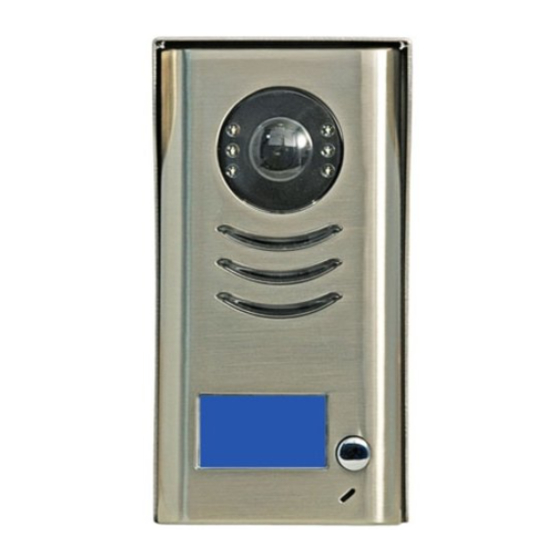
Door Camera - DPC-D241-1 User Manual
Parts and functions
• Full metal cover with backlight nameplate
• 4 Door cameras connection
• Directly connect 2 separate locks, unlock mode and unlock time controlled by Monitor
Name
Terminal Descriptions
Camera Lens
Night View LED
Speaker
Nameplate
Call Button
Microphone
90 mm
23 mm
1 2 3
MIC adjustment
SPK adjustment
S 2 + S -
P L S 1 +
B U S
Lock Control Jumper
Camera Code DIP
Main Connect Port
1
Advertisement

Subscribe to Our Youtube Channel
Related Manuals for XtendLan DPC-D241-1


Summary of Contents for XtendLan DPC-D241-1
-
Page 1: Parts And Functions
Door Camera - DPC-D241-1 User Manual Parts and functions • Full metal cover with backlight nameplate • 4 Door cameras connection • Directly connect 2 separate locks, unlock mode and unlock time controlled by Monitor Camera Lens Night View LED Speaker Nameplate Name Call Button Microphone 90 mm 23 mm Terminal Descriptions 1 2 3 Lock Control Jumper Camera Code DIP... - Page 2 • To select the lock type: when connecting a Electromechanical lock, set the jumper in 1-2 Lock Control Jumper: position; when connecting a Electromagnetical lock,set the jumper in 2-3 position. • Total 4 Camera can be supported Camera Code DIP: Set to the first Camera when multi Cameras are to be installed; Set to the Camera when there is only one Camera to be installed; Set to the second Camera when multi Cameras are to be installed; Set to the third Camera when multi Cameras are to be installed; Set to the fourth Camera when multi Cameras are to be installed; • To connect the bus line and the electronic locks. Main Connect Port: • BUS: Connect to the bus line, no polarity. • PL: External lock power input, connect to the power positive(power +). • S1+, S2+: Lock power(+) output, to connect 2 locks. • S-: Lock power(-) output, connect to the power(-) input of locks(only when using the camera to power the locks, if using the external power supply for the locks, the S- will not be connected). Inner Power 1 Lock Connection The standard inner power lock connection, use the Camera power to supply the lock, no need for external power supply. The Unlock Mode in the monitor need to be set: for Power-to-Unlock type lock, Unlock Mode set to 0(in Monitor, goto Main--> Setup--> Advanced Set--> Information page, then press and hold the Unlock Button for 2 seconds to open the Unlock Mode setting page); for Power-Off-to-Unlock type lock, Unlock Mode set to 1. Connection for Electromechanical lock Connection for Electromagnectical lock CALL CALL...
- Page 3 Inner Power 2 Locks Connection Directly connect 2 electronic locks to the door station and use the Camera power to supply the locks. There are 2 separate unlock icons on Monitor for opening each lock. Note that the 2 locks should be the same safety type. Connection for Electromechanical lock Connection for Electromagnectical lock CALL UNLOCK CALL TALK/MON UNLOCK TALK/MON IN-USE IN-USE MENU MENU Unlock Mode Unlock Mode 0: power-on-to-open 0: power-on-to-open 1: power-off-to-open 1: power-off-to-open 1 2 3 1 2 3 Jumper position in 2-3 Jumper position in 1-2...
-
Page 4: Electronic Specifications
Mounting Without Rain Cover 160-165cm Mounting With Rain Cover 160-165cm Electronic Specifications Lock Power supply: 12Vdc, 500mA(supplied by system) Power Consumtion: 1W in standby, 12W in working Video signal: ohm CCIR p-p NO, COM exchange contact: Max. 48V dc 1.5A Unlocking time: 1 to 9 seconds, set by Monitor Working temperature: -5ºC +45ºC...
Need help?
Do you have a question about the DPC-D241-1 and is the answer not in the manual?
Questions and answers