Table of Contents
Advertisement
Advertisement
Table of Contents

Subscribe to Our Youtube Channel
Related Manuals for ASROCK EP2C612D16T-4L


Summary of Contents for ASROCK EP2C612D16T-4L
-
Page 2: Copyright Notice
In no event shall ASRock Rack, its directors, oicers, employees, or agents be liable for any indirect, special, incidental, or consequential damages (including damages for loss of proits, loss of business, loss of data, interruption of business and the like), even if ASRock Rack has been advised of the possibility of such damages arising from any defect or error in the documentation or product. - Page 3 Contact Information If you need to contact ASRock Rack or want to know more about ASRock Rack, you’re welcome to visit ASRock Rack’s website at www.ASRockRack.com; or you may contact your dealer for further information. ASRock Rack Incorporation 6F., No.37, Sec. 2, Jhongyang S. Rd., Beitou District,...
-
Page 4: Table Of Contents
Contents Chapter 1 Introduction Package Contents Speciications Unique Features Motherboard Layout Onboard LED Indicators I/O Panel Block Diagram Chapter 2 Installation Screw Holes Pre-installation Precautions Installing the CPU Installing the CPU Fan and Heatsink Installation of Memory Modules (DIMM) Expansion Slots (PCI and PCI Express Slots) Jumper Setup Onboard Headers and Connectors Unit Identiication purpose LED/Switch... - Page 5 3.1.2 Navigation Keys Main Screen Advanced Screen 3.3.1 ACPI Coniguration 3.3.2 Conigure Super IO Settings 3.3.3 Serial Port Console Redirection 3.3.4 CSM Parameters 3.3.5 USB Coniguration 3.3.6 System Coniguration 3.3.7 Hard Disk S.M.A.R.T Settings 3.3.8 3rd Storage Coniguration 3.3.9 Voltage Coniguration 3.3.10 H/W Monitor 3.3.11 WHEA Coniguration 3.3.12 Easy RAID Installer...
- Page 6 Security Boot Screen Event Logs Exit Screen Chapter 4 Software Support Install Operating System Support CD Information 4.2.1 Running The Support CD 4.2.2 Drivers Menu 4.2.3 Utilities Menu 4.2.4 Contact Information Chapter 5 Troubleshooting Troubleshooting Procedures Technical Support Procedures Returning Merchandise for Service Chapter 6: Net Framework Installation Guide Installing .Net Framework 3.5.1 (For Server 2008 R2)
-
Page 7: Chapter 1 Introduction
In case any modiications of this manual occur, the updated version will be available on ASRock Rack website without further notice. You may ind the latest memory and CPU support lists on ASRock Rack website as well. ASRock Rack’s Website: www.ASRockRack.com If you require technical support related to this motherboard, please visit our website for speciic information about the model you are using. -
Page 8: Speciications
1.2 Speciications EP2C612D16T-4L MB Physical Status Form Factor SSI EEB Dimension 12'' x 13'' (30.5 cm x 33.0 cm) Processor System Intel® Xeon processor E5-2600/4600 v3 series (only support DDR3 sku) Socket Dual Socket LGA 2011 R3 Chipset Intel® C612... - Page 9 Type A USB 3.0 Port PSU SMBus Front Panel System BIOS BIOS Type 128Mb AMI UEFI Legal BIOS BIOS Features - Plug and Play (PnP) - ACPI 2.0 Compliance Wake Up Events - SMBIOS 2.8.1 Support - ASRock Rack Instant Flash...
- Page 10 Hardware Monitor Temperature - Motherboard Temperature Sensing - Card Side Temperature Sensing - CPU1 Temperature Sensing - CPU2 Temperature Sensing - CPU/Rear/Front Fan Tachometer - CPU Quiet Fan (Allow CPU Fan Speed Auto-Adjust by CPU Temperature) - CPU/Rear/Front Fan Multi-Speed Control Voltage Voltage Monitoring: +12V, +5V, +3.3V, CPU Vcore, DRAM, 1.05V_PCH, +BAT, 3VSB, 5VSB...
-
Page 11: Unique Features
POST or the <F2> key to enter into the BIOS setup menu to access ASRock Rack Instant Flash. Just launch this tool and save the new BIOS ile to your USB lash drive, loppy disk or hard drive, then you can update your BIOS only in a few clicks without preparing an additional loppy diskette or other complicated lash utility. -
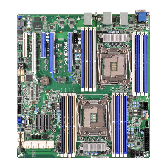
Page 12: Motherboard Layout
1.4 Motherboard Layout EP2C612D16T-4L 33.0cm (13.0 in) DDR3_G1 (64 bit, 240-pin module, Blue) ATXPWR1 IPMB1 PSU_SMB1 DDR3_G2 (64 bit, 240-pin module, White ATX12V2 FRNT_FAN2 DDR3_H1 (64 bit, 240-pin module, Blue) FRNT_FAN1 DDR3_H2 (64 bit, 240-pin module, White ATX12V1 DDR3_A1 (64 bit, 240-pin module,... - Page 13 EP2C612D16T-4L Description 2 x 240-pin DDR3 DIMM Slots (DDR3_G2, DDR3_H2, White) 2 x 240-pin DDR3 DIMM Slots (DDR3_G1, DDR3_H1, Blue) LGA 2011-3 CPU Socket (CPU2) ATX 12V Power Connector (ATX12V2) Intelligent Platform Management Bus header (IPMB1) PSU SMBus (PSU_SMB1) ATX Power Connector (ATXPWR1)
- Page 14 Description ME Recovery Jumper (ME_RECOVERY1) Speaker Header (SPEAKER1) USB 2.0 Header (USB_1_2) Vertical Type A USB 3.0 (USB3_5) USB 3.0 Header (USB3_3_4) System Panel Header (PANEL1) Auxiliary Panel Header (AUX_PANEL1) BMC SMBus Header (BMC_SMB1) TPM Header (TPM1) BMC SMBus Header (BMC_SMB3) BMC SMBus Header (BMC_SMB2) CPU PECI Mode Jumper (PECI1) Non Maskable Interrupt Button (NMI_BTN1)
-
Page 15: Onboard Led Indicators
EP2C612D16T-4L 1.5 Onboard LED Indicators DDR3_G1 (64 bit, 240-pin module, Blue) ATXPWR1 FAN_LED2 DDR3_G2 (64 bit, 240-pin module, White SB_PWR1 DDR3_H1 (64 bit, 240-pin module, Blue) FAN_LED1 DDR3_H2 (64 bit, 240-pin module, White DDR3_A1 (64 bit, 240-pin module, Blue DDR3_A2 (64 bit, 240-pin module, White) - Page 16 Status Description Amber FRNT_FAN2 failed Amber FRNT_FAN1 failed Green STB PWR ready Amber CPU1_FAN1 failed Amber FRNT_FAN3 failed Amber FRNT_FAN4 failed Green BMC heartbeat LED Amber CPU2_FAN1 failed Amber Rear_FAN2 failed Amber Rear_FAN1 failed...
-
Page 17: I/O Panel
EP2C612D16T-4L 1.6 I/O Panel No. Description No. Description Serial Port (COM1) USB 3.0 Ports (USB3_1_2) VGA Port (VGA1) UID Switch (UID) GLAN RJ-45 Port (LAN2)* GLAN RJ-45 Port (LAN4)* GLAN RJ-45 Port (LAN1)* GLAN RJ-45 Port (LAN3)* LAN RJ-45 Port (IPMI_LAN)* LAN Port LED Indications *here are two LED next to the LAN port. -
Page 18: Block Diagram
1.7 Block Diagram... -
Page 19: Chapter 2 Installation
EP2C612D16T-4L Chapter 2 Installation his is a SSI EEB form factor (12'' x 13'', 30.5 cm x 33.0 cm) motherboard. Before you install the motherboard, study the coniguration of your chassis to ensure that the motherboard its into it. EP2C612 Series are dual socket motherboards that support Intel® Xeon® E5-2600 v3 Series Processors. -
Page 20: Installing The Cpu
2.3 Installing the CPU 1. Before you insert the 2011-3-Pin CPU into the socket, please check if the PnP cap is on the socket, if the CPU surface is unclean, or if there are any bent pins in the socket. Do not force to insert the CPU into the socket if above situation is found. - Page 21 EP2C612D16T-4L...
- Page 22 he cover must be placed if returning the motherboard for ater service.
-
Page 23: Installing The Cpu Fan And Heatsink
EP2C612D16T-4L 2.4 Installing the CPU Fan and Heatsink Before you installed the heatsink, you need to spray thermal interface material between the CPU and the heatsink to improve heat dissipation. CPU fan for narrow ILM socket *Support an active or passive heatsink... -
Page 24: Installation Of Memory Modules (Dimm)
2.5 Installation of Memory Modules (DIMM) his motherboard provides sixteen 240-pin DDR3 (Double Data Rate 3) DIMM slots in two groups, and supports Quad Channel Memory Technology. Capacity CPU1 CPU2 DDR3_A1, B1, C1, D1 (Blue) DDR3_E1, F1, G1, H1 (Blue) 256GB DDR3_A2, B2, C2, D2 (White) DDR3_E2, F2, G2, H2 (White) - Page 25 EP2C612D16T-4L he DIMM only its in one correct orientation. It will cause permanent damage to the motherboard and the DIMM if you force the DIMM into the slot at incorrect orientation.
- Page 26 Recommended Memory Conigurations A single memory module should be installed in the BLUE socket. If you install only one CPU (CPU1) on the motherboard, make sure to install DIMMs into DDR3_A, DDR3_B, DDR3_C, or DDR3_D slot(s). 1 CPU Coniguration CPU1 1 DIMM 2 DIMMS 4 DIMMS...
-
Page 27: Expansion Slots (Pci And Pci Express Slots)
EP2C612D16T-4L 2.6 Expansion Slots (PCI and PCI Express Slots) here are 5 PCI Express slots on this motherboard. PCIE slot: PCIE3 (PCIE 3.0 x8 slot, from CPU 1) is used for PCI Express x8 lane width cards. PCIE1 (PCIE 2.0 x8 slot, from CPU 2) is used for PCI Express x8 lane width cards. -
Page 28: Installing An Expansion Card
Installing an expansion card Step 1. Before installing an expansion card, please make sure that the power supply is switched of or the power cord is unplugged. Please read the documentation of the expansion card and make necessary hardware settings for the card before you start the installation. Step 2. -
Page 29: Jumper Setup
EP2C612D16T-4L 2.7 Jumper Setup he illustration shows how jumpers are setup. When the jumper cap is placed on the pins, the jumper is “Short”. If no jumper cap is placed on the pins, the jumper is “Open”. he illustration shows a 3-pin jumper whose pin1 and pin2 are “Short”... - Page 30 Chassis ID Jumpers Chassis ID0 Jumper (3-pin CHASSIS_ID0) (see p.6, No. 49) Chassis ID1 Jumper (3-pin CHASSIS_ID1) (see p.6, No. 48) Chassis ID2 Jumper (3-pin CHASSIS_ID2) (see p.6, No. 50) Board Level SKU (Default) Reserved for system level Chassis ID0 Jumper (3-pin CHASSIS_ID0) (see p.6, No.
- Page 31 EP2C612D16T-4L Chassis ID0 Jumper (3-pin CHASSIS_ID0) (see p.6, No. 49) Chassis ID1 Jumper (3-pin CHASSIS_ID1) (see p.6, No. 48) Chassis ID2 Jumper (3-pin CHASSIS_ID2) Reserved for system level Reserved for system level (see p.6, No. 50)
-
Page 32: Onboard Headers And Connectors
2.8 Onboard Headers and Connectors Onboard headers and connectors are NOT jumpers. Do NOT place jumper caps over these headers and connectors. Placing jumper caps over the headers and connectors will cause permanent damage to the motherboard. PLED+ System Panel Header Con nec t t he power sw itch, PLED- PWRBTN#... - Page 33 EP2C612D16T-4L Auxiliary Panel Header his header supports multiple (18-pin AUX PANEL1) functions on the front panel, (see p.6, No. 40) including the front panel SMB, internet status indicator and chassis intrusion pin. A. Front panel SMBus connecting pin (6-1 pin FPSMB) his header allows you to connect SMBus (System Management Bus) equipment.
- Page 34 Serial ATA3 Connectors hese twelve SATA3 (SATA_0) connectors support SATA (see p.6, No. 21) data cables for internal storage (SATA_1) devices with up to 6.0 Gb/s (see p.6, No. 20) data transfer rate. (SATA_2) (see p.6, No. 23) (SATA_3) (see p.6, No. 22) (SATA_4) (see p.6, No.
- Page 35 Fan) connectors. If you plan FAN_SPEED_CONTROL to connect a 3-Pin CPU fan, (4-pin CPU2_FAN1) please connect it to Pin 1-3. *For more details, please refer to the (see p.6, No. 59) Cooler QVL list on the ASRock Rack website. +12V CPU_F AN_SPEED FAN_SPEED_CONTROL...
- Page 36 Front and Rear Fan Please connect fan cables to the Connectors fan connectors and match the (4-pin FRNT_FAN1) black wire to the ground pin. FAN_VOLTAGE FAN_SPEED (see p.6, No. 9) All fans support Fan Control. FAN_SPEED_CONTROL (4-pin FRNT_FAN2) (see p.6, No. 8) (4-pin FRNT_FAN3) (see p.6, No.
- Page 37 EP2C612D16T-4L TPM Header his connector supports (17-pin TPM1) Trusted Platform Module (see p.6, No. 42) (TPM) system, which can securely store keys, digital certiicates, passwords, and data. A TPM system also helps enhance network security, protects digital identities, and ensures platform integrity.
- Page 38 Baseboard Management hese headers are used for the BMC_SMBDATA Controller SMBus Headers SM BUS devices.. BMC_SMBCLK (5-pin BMC_SMB1) Power (see p.6, No. 41) BMC_SMB_PRESENT_1_N (5-pin BMC_SMB3) (see p.6, No. 43) (5-pin BMC_SMB2) (see p.6, No. 44) LAN4_LINK Front LAN LED his 4-pin connector is used LED_PWR Connector...
-
Page 39: Unit Identiication Purpose Led/Switch
EP2C612D16T-4L 2.9 Unit Identiication purpose LED/Switch With the UID button, You are able to locate the server you’re working on from behind a rack of servers. Unit Identiication When the UID button on the purpose LED/Switch front or rear panel is pressed,... -
Page 40: Dual Lan And Teaming Operation Guide
2.11 Dual LAN and Teaming Operation Guide Dual LAN with Teaming enabled on this motherboard allows two single connections to act as one single connection for twice the transmission bandwidth, making data transmission more efective and improving the quality of transmission of distant images. -
Page 41: Chapter 3 Uefi Setup Utility
EP2C612D16T-4L Chapter 3 UEFI Setup Utility 3.1 Introduction his section explains how to use the UEFI SETUP UTILITY to conigure your system. he UEFI chip on the motherboard stores the UEFI SETUP UTILITY. You may run the UEFI SETUP UTILITY when you start up the computer. Please press <F2> or <Del> during the Power-On-Self-Test (POST) to enter the UEFI SETUP UTILITY;... -
Page 42: Navigation Keys
3.1.2 Navigation Keys Please check the following table for the function description of each navigation key. Navigation Key(s) Function Description Moves cursor let or right to select Screens Moves cursor up or down to select items + / - To change option for the selected items <Tab>... -
Page 43: Main Screen
EP2C612D16T-4L 3.2 Main Screen Once you enter the UEFI SETUP UTILITY, the Main screen will appear and display the system overview. he Main screen provides system overview information and allows you to set the system time and date. -
Page 44: Advanced Screen
3.3 Advanced Screen In this section, you may set the conigurations for the following items: ACPI Conigura- tion, Conigure Super IO Settings, Serial Port Console Redirection, CSM Parameters, USB Coniguration, System Coniguration, Hard Disk S.M.A.R.T Settings, 3rd Storage Conigu- ration, Voltage Coniguration, H/W Monitor, WHEA Coniguration, Easy RAID Installer and Instant Flash. -
Page 45: Acpi Coniguration
EP2C612D16T-4L 3.3.1 ACPI Coniguration PCIE Devices Power On his allows the system to be waked up by a PCIE device and enables wake on LAN. Ring-In Power On Use this item to enable or disable Ring-In signals to turn on the system from the power- sot-of mode. -
Page 46: Conigure Super Io Settings
3.3.2 Conigure Super IO Settings Serial Port 1 Coniguration Use this item to conigure the onboard serial port 1. Select and enter the "Serial Port 1 Coniguration" and you will see the followings: Serial Port Use this item to enable or disable the serial port. Change Settings Use this item to select an optimal setting for Super IO device. -
Page 47: Serial Port Console Redirection
EP2C612D16T-4L 3.3.3 Serial Port Console Redirection COM1 Console Redirection Use this option to enable or disable Console Redirection. If this item is set to Enabled, you can select a COM Port to be used for Console Redirection. Console Redirection Settings Use this option to conigure Console Redirection Settings, and specify how your computer and the host computer to which you are connected exchange information. - Page 48 Bits Per Second Use this item to select the serial port transmission speed. The speed used in the host computer and the client computer must be the same. Long or noisy lines may require lower transmission speed. he options include [9600], [19200], [57600] and [115200]. Data Bits Use this item to set the data transmission size.
-
Page 49: Console Redirection
EP2C612D16T-4L Serial Port for Out-of-Band Management/Windows Emergency Management Services (EMS) Console Redirection Use this option to enable or disable Console Redirection. If this item is set to Enabled, you can select a COM Port to be used for Console Redirection. -
Page 50: Csm Parameters
3.3.4 CSM Parameters Boot Option Filter Use this option to control what devices system can boot to. Coniguration options: [UEFI and Legacy], [Legacy only] and [UEFI only]. Launch Storage OpROM Policy Select UEFI only to run those that support UEFI option ROM only. Select Legacy only to run those that support legacy option ROM only. -
Page 51: Usb Coniguration
EP2C612D16T-4L 3.3.5 USB Coniguration Intel USB3.0 Mode Enable or disable all the USB 3.0 ports. Legacy USB 3.0 Support Use this option to select legacy support for USB devices. There are four configuration options: [Enabled], [Auto], [Disabled] and [UEFI Setup Only]. he default value is [Enabled]. -
Page 52: System Coniguration
3.3.6 System Coniguration Primary Graphics Adapter If PCI Express graphics card is installed on the motherboard, you may use this option to select PCI Express or Onboard as the primary graphics adapter. Onboard VGA Use this to enable or disable the Onboard VGA function. he default value is [Auto]. Onboard LAN1 his allows you to enable or disable the Onboard LAN 1 feature. - Page 53 EP2C612D16T-4L Restore on AC/Power Loss his allows you to set the power state ater an unexpected AC/power loss. If [Power Of] is selected, the AC/power remains of when the power recovers. If [Power On] is selected, the AC/power resumes and the system starts to boot up when the power recovers. If [Last...
-
Page 54: Hard Disk S.m.a.r.t Settings
3.3.7 Hard Disk S.M.A.R.T Settings Hard Disk S.M.A.R.T. Use this item to enable or disable the S.M.A.R.T. (Self-Monitoring, Analysis, and Reporting Technology) feature. Coniguration options: [Disabled] and [Enabled]. -
Page 55: 3Rd Storage Coniguration
EP2C612D16T-4L 3.3.8 3rd Storage Coniguration Marvell 9172 Controller Enable or disable Marvell 9172 Controller. Marvell 9172 Operation Mode his item is for M_SATA ports. Use this to select Marvell SATA operation mode. Coniguration options: [IDE Mode], [AHCI Mode] and [RAID Mode]. he default value is [AHCI Mode]. -
Page 56: Voltage Coniguration
3.3.9 Voltage Coniguration DRAM 1 Voltage Use this item to set the DRAM 1 Voltage Coniguration. DRAM 2 Voltage Use this item to set the DRAM 2 Voltage Coniguration. -
Page 57: H/W Monitor
EP2C612D16T-4L 3.3.10 H/W Monitor In this section, it allows you to monitor the status of the hardware on your system, includ- ing the parameters of the CPU temperature, motherboard temperature, CPU fan speed, chassis fan speed, and the critical voltage. -
Page 58: Watch Dog Timer
FRNT_FAN3 his allows you to set the front fan 3’s speed. he default value is [Smart Fan]. FRNT_FAN4 his allows you to set the front fan 4’s speed. he default value is [Smart Fan]. Smart Fan Control his allows you to set the Smart fan’s level speed. Smart Fan Duty Control Smart Fan Duty x (x means 1 to 11 stage) his allows you to set duty cycle for each stage. -
Page 59: Whea Coniguration
EP2C612D16T-4L 3.3.11 WHEA Coniguration WHEA Support Use this item to enable or disable Windows Hardware Error Architecture. System Error Use this item to enable or disable System Error feature. When it is set to [Enabled], you can conigure Memory Error and PCIE Error log features. -
Page 60: Easy Raid Installer
3.3.12 Easy RAID Installer Easy RAID Installer can help you to copy the RAID driver from a support CD to your USB storage device. Ater copying the RAID driver to your USB storage device, please change “SATA Mode” to “RAID”, then you can start installing the OS in RAID mode. -
Page 61: Instant Flash
EP2C612D16T-4L 3.3.13 Instant Flash Instant Flash is a UEFI lash utility embedded in Flash ROM. his convenient UEFI update tool allows you to update system UEFI without entering operating systems ® irst like MS-DOS or Windows . Just save the new UEFI ile to your USB lash drive,... -
Page 62: Intelrcsetup
3.4 IntelRCSetup In this section, you may set the conigurations for the following items: Processor Conigu- ration, CPU Power Management Coniguration, Memory Coniguration, IIO Conigura- tion, PCH Coniguration and Server ME Coniguration. -
Page 63: Processor Coniguration
EP2C612D16T-4L 3.4.1 Processor Coniguration Per-Socket Coniguration Change Per-Socket Settings. CPU Socket 0 Coniguration Active Processor Cores Enter the number of cores to be enabled. 0 means all cores. 14 cores are available. CPU Socket 1 Coniguration Active Processor Cores Enter the number of cores to be enabled. 0 means all cores. 14 cores are available. -
Page 64: Hardware Prefetcher
Enable SMX Use this item to enable Safer Mode Extensions. Hardware Prefetcher Automatically prefetch data and code for the processor. Enable for better performance. Adjacent Cache Prefetch Automatically prefetch the subsequent cache line while retrieving the currently requested cache line. Enable for better performance. -
Page 65: Cpu Power Management Coniguration
EP2C612D16T-4L 3.4.2 CPU Power Management Coniguration Intel SpeedStep Technology Intel SpeedStep technology is Intel’s new power saving technology. Processors can switch between multiple frequencies and voltage points to enable power saving. he default value is [Enabled]. Configuration options: [Enabled] and [Disabled]. If you install Windows®... - Page 66 CPU C6 State Support Enable C6 deep sleep state for lower power consumption. CPU Thermal Throttling Enable CPU internal thermal control mechanisms to keep the CPU from overheating.
-
Page 67: Memory Coniguration
EP2C612D16T-4L 3.4.3 Memory Coniguration Enforce POR Enable to enforce POR restrictions for DDR3 frequency and voltage programming. DRAM Frequency ECC Support Use this item to enable or disable DDR ECC Support. MRC Fast Boot When enabled, portions of memory reference code will be skipped when possible to increase boot speed. - Page 68 RAS Mode Enable or disable RAS modes. Enabling Sparing and Mirroring is not supported. If enabled, Sparing will be selected.
-
Page 69: Iio Coniguration
EP2C612D16T-4L 3.4.4 IIO Coniguration PCIe Hot Plug Use this item to enable or disable PCIe Hot Plug globally. PCIe ACPI Hot Plug Use this item to enable or disable PCIe ACPI Hot Plug globally. PCIE 1 & PCIE 2 Link Width Use this item to select PCIe port Bifurcation for selected slot(s). - Page 70 PCIE 4 Link Speed his allows you to select PCIE 4 Link Speed. he default value is [Auto]. PCIE 6 Link Width Use this item to select PCIe port Bifurcation for selected slot(s). PCIE 6 - Port A Link Speed Use this item to conigure the link speed between PCIe 6 and IOU, Port A.
-
Page 71: Pch Coniguration
EP2C612D16T-4L 3.4.5 PCH Coniguration PCI-E ASPM Support Use this option to enable or disable the ASPM support for all downstream devices. PCH sSATA Coniguration sSATA devices and settings sSATA Controller Use this item to enable or disable SATA Controller. sSATA Mode Selection Identify the SATA port is connected to Solid State Drive or Hard Disk Drive. - Page 72 Spin Up Device If enabled for any of ports, Staggered Spin Up will be performed and only the drives which have this option enabled will spin up at boot. Otherwise all drives spin up at boot. sSATA Rx Setting Adjust sSATA DTLE DATA Values (0-15). sSATA Device Type Identify the SATA port connected to Solid State Drive or Hard Disk Drive.
-
Page 73: Server Me Coniguration
EP2C612D16T-4L 3.4.6 Server ME Coniguration Spread Spectrum Use this item to select spread specturm mode. -
Page 74: Server Mgmt
3.5 Server Mgmt Wait For BMC Wait For BMC response for speciied time out. In PILOTII, BMC starts at the same time when BIOS starts during AC power ON. It takes around 30 seconds to initialize Host to BMC interfaces. System Event Log Press <Enter>... - Page 75 EP2C612D16T-4L BMC Network Coniguration Press <Enter> to conigure BMC Network parameters. Coniguration Address Source Select to conigure BMC network parameters statically or dynamically(by BIOS or BMC). Coniguration options: [Unspeciied], [Static], and [Dynamic]. Unspeciied: BMC network parameters are conigured by BMC itself.
-
Page 76: Ipmi Port
Please refer to the table below for the LAN interface mapping to check the MAC address through either BIOS or Web interface. BMC LAN Interface Mapping Table I/O Panel BIOS Menu IPMI Web Page LAN1 Port (NCSI) Lan Channel 1 eth0 IPMI Port Lan Channel 2... -
Page 77: Security
EP2C612D16T-4L 3.6 Security In this section, you may set or change the supervisor/user password for the system. For the user password, you may also clear it. Supervisor Password Set or change the password for the administrator account. Only the administrator has authority to change the settings in the UEFI Setup Utility. -
Page 78: Boot Screen
3.7 Boot Screen In this section, it will display the available devices on your system for you to conigure the boot settings and the boot priority. Boot Option #1 Use this item to set the system boot order. Boot From Onboard LAN Use this item to enable or disable the Boot From Onboard LAN feature. - Page 79 EP2C612D16T-4L Full Screen Logo Use this item to enable or disable OEM Logo. he default value is [Enabled]. AddOn ROM Display Use this option to adjust AddOn ROM Display. If you enable the option “Full Screen Logo” but you want to see the AddOn ROM information when the system boots, please select...
-
Page 80: Event Logs
3.8 Event Logs Change Smbios Event Log Settings his allows you to conigure the Smbios Event Log Settings. When entering the item, you will see the followings: Smbios Event Log Use this item to enable or disable all features of the SMBIOS Event Logging during system boot. -
Page 81: View Smbios Event Log
EP2C612D16T-4L View Smbios Event Log Press <Enter> to view the Smbios Event Log records. All values changed here do not take efect until computer is restarted. -
Page 82: Exit Screen
3.9 Exit Screen Save Changes and Exit When you select this option, the following message “Save coniguration changes and exit setup?” will pop-out. Press <F10> key or select [Yes] to save the changes and exit the UEFI SETUP UTILITY. Discard Changes and Exit When you select this option, the following message “Discard changes and exit setup?”... -
Page 83: Chapter 4 Software Support
4.2.4 Contact Information If you need to contact ASRock Rack or want to know more about ASRock Rack, welcome to visit ASRock Rack’s website at http://www.ASRockRack.com; or you may contact your... -
Page 84: Chapter 5 Troubleshooting
Chapter 5 Troubleshooting 5.1 Troubleshooting Procedures Follow the procedures below to troubleshoot your system. Always unplug the power cord before adding, removing or changing any hardware com- ponents. Failure to do so may cause physical injuries to you and damages to motherboard components. - Page 85 1. Verify if the battery on the motherboard provides ~3VDC. Install a new battery if it does not. 2. Conirm whether your power supply provides adaquate and stable power. Other problems... 1. Try searching keywords related to your problem on ASRock Rack’s FAQ page: http://www.asrockrack.com/support...
-
Page 86: Technical Support Procedures
5.2 Technical Support Procedures If you have tried the troubleshooting procedures mentioned above and the problems are still unsolved, please contact ASRock Rack’s technical support with the following information: 1. Your contact information 2. Model name, BIOS version and problem type. -
Page 87: Chapter 6: Net Framework Installation Guide
EP2C612D16T-4L Chapter 6: Net Framework Installation Guide ® To let Intel RSTe works properly, it is required to install Net Framework. Please follow the ® ® steps below to enable “.Net Framework” feature on Microsot Windows Server 2008 R2. 6.1 Installing .Net Framework 3.5.1 (For Server 2008 R2) 1. - Page 88 3. Check the box next to .Net Framework 3.5.1 and then click Next. 4. Click Next to continue.
- Page 89 EP2C612D16T-4L 5. Click Install to start installing .Net Framework 3.5.1. 6. Ater the installation completes, click Close.
Need help?
Do you have a question about the EP2C612D16T-4L and is the answer not in the manual?
Questions and answers