Table of Contents
Advertisement
Advertisement
Table of Contents

Related Manuals for ASROCK EP2C612 WS


Summary of Contents for ASROCK EP2C612 WS
-
Page 2: Copyright Notice
In no event shall ASRock Rack, its directors, oicers, employees, or agents be liable for any indirect, special, incidental, or consequential damages (including damages for loss of proits, loss of business, loss of data, interruption of business and the like), even if ASRock Rack has been advised of the possibility of such damages arising from any defect or error in the documentation or product. - Page 3 Contact Information If you need to contact ASRock Rack or want to know more about ASRock Rack, you’re welcome to visit ASRock Rack’s website at www.ASRockRack.com; or you may contact your dealer for further information. ASRock Rack Incorporation 6F., No.37, Sec. 2, Jhongyang S. Rd., Beitou District,...
-
Page 4: Table Of Contents
Contents Chapter 1 Introduction Package Contents Speciications Unique Features Motherboard Layout Onboard LED Indicators I/O Panel Block Diagram Chapter 2 Installation Screw Holes Pre-installation Precautions Installing the CPU Installing the CPU Fan and Heatsink Installation of Memory Modules (DIMM) Expansion Slots (PCI Express Slots) Jumper Setup Onboard Headers and Connectors Dr. - Page 5 2.11 CrossFireX , 3-Way CrossFireX , 4-Way CrossFireX Quad CrossFireX Operation Guide 2.11.1 Installing Two CrossFireX -Ready Graphics Cards 2.11.2 Installing Three CrossFireX -Ready Graphics Cards 2.11.3 Installing Four CrossFireX -Ready Graphics Cards 2.11.4 Driver Installation and Setup 2.12 Driver Installation Guide 2.13 Dual LAN and Teaming Operation Guide Chapter 3 UEFI Setup Utility...
- Page 6 3.4.10 Intel ME Coniguration 3.4.11 WHEA Coniguration 3.4.12 Easy RAID Installer 3.4.13 Instant Flash Server Mgmt 3.5.1 System Event Log 3.5.2 BMC Network Coniguration Security Screen Boot Screen 3.7.1 CSM Parameters Event Logs Exit Screen Chapter 4 Software Support Install Operating System Support CD Information 4.2.1 Running The Support CD 4.2.2 Drivers Menu...
- Page 7 Chapter 6: Net Framework Installation Guide Installing .Net Framework 3.5.1 (For Server 2008 R2)
-
Page 8: Chapter 1 Introduction
In case any modiications of this manual occur, the updated version will be available on ASRock Rack website without further notice. You may ind the latest memory and CPU support lists on ASRock Rack website as well. ASRock Rack’s Website: www.ASRockRack.com If you require technical support related to this motherboard, please visit our website for speciic information about the model you are using. -
Page 9: Speciications
1.2 Speciications EP2C612 WS MB Physical Status Form Factor SSI EEB Dimension 12'' x 13'' (30.5 cm x 33.0 cm) Processor System Intel® Xeon processor E5-2600/4600 & v3 series Socket Dual Socket LGA 2011 R3 Chipset Intel® C612 System Memory... - Page 10 Front Panel 4 pin 5V box connector System BIOS BIOS Type 128Mb AMI UEFI Legal BIOS BIOS Features - Plug and Play (PnP) - ACPI 2.0 Compliance Wake Up Events - SMBIOS 2.8.0 Support - ASRock Rack Instant Flash Hardware Monitor...
- Page 11 Temperature - CPU Temperature Sensing - System Temperature Sensing - System Inlet Temperature Sensing - Card-side Temperature Sensing - CPU/Rear/Front Fan Tachometer - CPU Quiet Fan (Allow Chassis Fan Speed Auto-Adjust by CPU Temperature) - CPU/Rear/Front Fan Multi-Speed Control Voltage Voltage Monitoring: +12V, +5V, +3.3V, CPU Vcore, DRAM, 1.05V_PCH, +BAT, 3.3VSB, 5VSB Support OS...
- Page 12 his motherboard supports Wake from on Board LAN. To use this function, please make sure that the “Wake on Magic Packet from power of state” is enabled in Device Manager > Intel® Ethernet Connection > Power Management. And the “PCI Devices Power On” is enabled in UEFI SETUP UTILITY >...
-
Page 13: Unique Features
POST or the <F2> key to enter into the BIOS setup menu to access ASRock Rack Instant Flash. Just launch this tool and save the new BIOS ile to your USB lash drive, loppy disk or hard drive, then you can update your BIOS only in a few clicks without preparing an additional loppy diskette or other complicated lash utility. -
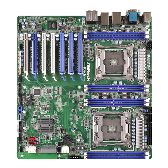
Page 14: Motherboard Layout
EP2C612 WS 1.4 Motherboard Layout 33.0 cm (13 in) ATXPWR1 USB 3.0 PSU_SMB1 T: USB1 Keyboard REAR_FAN1 CPU2_FAN1 /Mouse ATX12V1 B: USB2 ATX12V2 PMBUS_SEL_ALT1 PMBUS_SEL_DAT1 PMBUS_SEL_CLK1 CPU1_FAN1 USB 3.0 IPMI T: USB1 B: USB2 CPU2 LAN2 LAN1 CPU1 PCIE7 (Blue, from CPU1) - Page 15 Description 2 x 288-pin DDR4 DIMM Slots (DDR4_E1, DDR4_F1, Blue) ATX 12V Power Connector (ATX12V2) Rear Fan Connector (REAR_FAN1) CPU 2 Fan Connector (CPU2_FAN1) 2 x 288-pin DDR4 DIMM Slots (DDR4_G1, DDR4_H1, Blue) 2 x 288-pin DDR4 DIMM Slots (DDR4_A1, DDR4_B1, Blue) CPU 1 Fan Connector (CPU1_FAN1) PSU SMBus (PSU_SMB1) PMBUS Mode Jumper (PMBUS_SEL_ALT1)
- Page 16 EP2C612 WS Description Auxiliary Panel Header (AUX_PANEL1) SATA DOM Power Jumper 2 (SATAPWR_SEL2) USB 3.0 Header (USB3_4_5) Vertical Type A USB 3.0 (USB3_7) USB 2.0 Header (USB_1_2) Speaker Header (SPEAKER1) Front Fan Connector (FRNT_FAN3) Front Fan Connector (FRNT_FAN4) hermal Sensor Header (TR1)
-
Page 17: Onboard Led Indicators
DDR4_D1 (64 bit, 288-pin module, Blue) DDR4_C1 (64 bit, 288-pin module, Blue) DDR4_A1 (64 bit, 288-pin module, Blue) DDR4_B1 (64 bit, 288-pin module, Blue) DDR4_H1 (64 bit, 288-pin module, Blue) DDR4_G1 (64 bit, 288-pin module, Blue) DDR4_E1 (64 bit, 288-pin module, Blue) DDR4_F1 (64 bit, 288-pin module, Blue) English... - Page 18 EP2C612 WS Status Description Amber Rear_FAN1 failed Amber CPU2_FAN1 failed Amber CPU1_FAN1 failed Green STB PWR ready Amber Front_FAN2 failed Amber Front_FAN1 failed Amber Front_FAN3 failed Amber Front_FAN4 failed Green BMC heartbeat LED...
-
Page 19: I/O Panel
1.6 I/O Panel No. Description No. Description PS/2 Mouse/Keyboard Port LAN RJ-45 Port (LAN1)** USB 3.0 Ports (USB3_1_2) Central / Bass (Orange) Serial Port (COM1) Rear Speaker (Black) VGA Port (VGA1) Optical SPDIF Out Port LAN RJ-45 Port (IPMI_LAN)* Line In (Light Blue) USB 3.0 Ports (USB3_3_4) Front Speaker (Lime)*** LAN RJ-45 Port (LAN2)**... - Page 20 EP2C612 WS **here are two LEDs on each LAN port. Please refer to the table below for the LAN port LED indications. ACT/LINK LED SPEED LED LAN Port LAN Port (LAN1, LAN2) LED Indications Activity / Link LED Speed LED...
-
Page 21: Block Diagram
1.7 Block Diagram... -
Page 22: Chapter 2 Installation
EP2C612 WS Chapter 2 Installation his is a SSI EEB form factor (12'' x 13'', 30.5 cm x 33.0 cm) motherboard. Before you install the motherboard, study the coniguration of your chassis to ensure that the motherboard its into it. -
Page 23: Installing The Cpu
2.3 Installing the CPU 1. Before you insert the 2011-3-Pin CPU into the socket, please check if the PnP cap is on the socket, if the CPU surface is unclean, or if there are any bent pins in the socket. Do not force to insert the CPU into the socket if above situation is found. - Page 24 EP2C612 WS...
- Page 25 he cover must be placed if returning the motherboard for ater service.
-
Page 26: Installing The Cpu Fan And Heatsink
EP2C612 WS 2.4 Installing the CPU Fan and Heatsink Before you installed the heatsink, you need to spray thermal interface material between the CPU and the heatsink to improve heat dissipation. -
Page 27: Installation Of Memory Modules (Dimm)
2.5 Installation of Memory Modules (DIMM) his motherboard provides eight 288-pin DDR4 (Double Data Rate 4) DIMM slots, and supports Quad Channel Memory Technology. 1. It is not allowed to install a DDR, DDR2 or DDR3 memory module into a DDR4 slot; otherwise, this motherboard and DIMM may be damaged. - Page 28 EP2C612 WS Quad Channel Memory Conigurations CPU2 Priority *he symbol # indicates the slot is populated by a memory module.
- Page 29 he DIMM only its in one correct orientation. It will cause permanent damage to the motherboard and the DIMM if you force the DIMM into the slot at incorrect orientation.
-
Page 30: Expansion Slots (Pci Express Slots)
EP2C612 WS 2.6 Expansion Slots (PCI Express Slots) here are 7 PCI Express slots on this motherboard. PCIE slot: PCIE1 (PCIE 3.0 x16 slot, from CPU 2) is used for PCI Express x16 lane width cards. PCIE2 (PCIE 3.0 x16 slot, from CPU 1) is used for PCI Express x8 lane width cards. -
Page 31: Installing An Expansion Card
PCI Express Slot Coniguration (SLI and CrossFireX Mode) PCIE1 PCIE3 PCIE5 PCIE7 Two Graphics Cards in CrossFireX or SLI Mode hree Graphics Cards in 3-Way CrossFireX or 3-Way Mode Four Graphics Cards in 4-Way CrossFireX or 4-Way Mode For a better thermal environment, please connect a chassis fan to the motherboard’s chassis fan connector (CHA_FAN1, CHA_FAN2 or CHA_FAN3) when using mul- tiple graphics cards. -
Page 32: Jumper Setup
EP2C612 WS 2.7 Jumper Setup he illustration shows how jumpers are setup. When the jumper cap is placed on the pins, the jumper is “Short”. If no jumper cap is placed on the pins, the jumper is “Open”. he illustration shows a 3-pin jumper whose pin1 and pin2 are “Short”... - Page 33 Chassis ID1 Jumper (3-pin CHASSIS_ID1) (see p.6, No. 54) Chassis ID2 Jumper (3-pin CHASSIS_ID2) (see p.6, No. 52) Chassis ID3 Jumper (3-pin CHASSIS_ID3) (see p.6, No. 50) Board Level SKU (Default) Reserved for system level Chassis ID1 Jumper (3-pin CHASSIS_ID1) (see p.6, No.
- Page 34 EP2C612 WS CPU PECI Mode Jumper (3-pin PECI1) (see p.6, No. 16) CPU PECI connect to PCH CPU PECI connect to BMC (Default) PMBUS Mode Jumper (3-pin PMBUS_SEL_ALT1) (see p.6, No. 9) PMBus connected to BMC PMBus connected to PCH...
-
Page 35: Onboard Headers And Connectors
2.8 Onboard Headers and Connectors Onboard headers and connectors are NOT jumpers. Do NOT place jumper caps over these headers and connectors. Placing jumper caps over the headers and connectors will cause permanent damage to the motherboard. PLED+ System Panel Header Con nec t t he power sw itch, PLED- PWRBTN#... - Page 36 EP2C612 WS Auxiliary Panel Header his header supports multiple (18-pin AUX PANEL_1) functions on the front panel, (see p.6, No. 34) including the front panel SMB, internet status indicator and chassis intrusion pin. A. Front panel SMBus connecting pin (6-1 pin FPSMB) his header allows you to connect SMBus (System Management Bus) equipment.
- Page 37 Serial ATA3 Connectors hese eight SATA3 connectors (SATA_0) support SATA data cables for (see p.6, No. 18) internal storage devices with (SATA_1) up to 6.0 Gb/s data transfer (see p.6, No. 23) rate. (SATA_2) (see p.6, No. 25) (SATA_3) (see p.6, No. 19) (SATA_4) (see p.6, No.
- Page 38 EP2C612 WS Serial ATA3 DOM he SATA3 DOM Connectors connectors supports (SSATA_2) both a SATA DOM (see p.6, No. 32) (Disk-On-Module) and (SSATA_3) a SATA data cable for (see p.6, No. 30) internal storage device. Consult the documentation that comes with your SATA DOM and check whether or not Pin 7 requires 5V power supply.
- Page 39 IntA_PA_D+ USB 3.0 Header Besides four default USB 3.0 IntA_PA_D- (19-pin USB3_5_6) ports on the I/O panel, there IntA_PA_SSTX+ IntA_PA_SSTX- (see p.6, No. 36) is one USB 3.0 header on this IntA_PA_SSRX+ IntA_PA_SSRX- motherboard. This USB 3.0 Vbus header can support two USB 3.0 ports.
- Page 40 (4-pin CPU2_FAN1) to connect a 3-Pin CPU fan, (see p.6, No. 4) please connect it to Pin 1-3. *For more details, please refer to the Cooler QVL list on the ASRock Rack website. FAN_VOLTAGE CPU_FAN_SPEED FA N_SPEED_CONTROL Front and Rear Fan...
- Page 41 ATX Power Connector his motherboard provides a (24-pin ATXPWR1) 24-pin ATX power connector. (see p.6, No. 12) To use a 20-pin ATX power supply, please plug it along Pin 1 and Pin 13. ATX 12V Power his motherboard provides +12V2 Connectors two 8-pin ATX 12V power (8-pin ATX12V1)
- Page 42 EP2C612 WS SCLOCK Serial General Purpose This header supports Serial SLOAD Input/Output Headers Li n k i nter face for onboa rd (7-pin SATA_SGPIO1) SATA connections. (see p.6, No. 43) (7-pin SATA_SGPIO2) SDATAOUT (see p.6, No. 44) (7-pin SSATA_SGPIO1) (see p.6, No. 45)
- Page 43 hermal Sensor Header Please connect the thermal (3-pin TR1) sensor cable to either pin 1-2 (see p.6, No. 42) or pin 2-3 and the other end to the device which you wish to monitor its temperature. PCIe Power Connector Please connect a 4 pin molex (4-pin PCIE_PWR1) power cable to this connector (see p.6, No.
-
Page 44: Dr. Debug
EP2C612 WS 2.9 Dr. Debug Dr. Debug is used to provide code information, which makes troubleshooting even easier. Please see the diagrams below for reading the Dr. Debug codes. Code Description Please check if the CPU is installed correctly and then clear CMOS. -
Page 45: Sli Tm
2.10 SLI , 3-Way SLI , 4-Way SLI and Quad SLI Operation Guide his motherboard supports NVIDIA® SLI , 3-way SLI , 4-way SLI and Quad (Scalable Link Interface) technology that allows you to install up to four identical PCI Express x16 graphics cards. Currently, NVIDIA® SLI and Quad technology supports Windows®... - Page 46 EP2C612 WS Step 3 Align and insert the SLI_Bridge_3S Card to the goldingers on each graphics card. Make sure the SLI_Bridge_3S Card is irmly in place. SLI_Bridge_3S Card SLI_Bridge_3S Card Step 4 Connect a VGA cable or a DVI cable to the...
-
Page 47: Installing Three Sli Tm -Ready Graphics Cards
2.10.2 Installing Three SLI -Ready Graphics Cards Step 1 Insert one graphics card into PCIE1 slot, another graphics card to PCIE3 slot, and the other graphics card to PCIE5 slot, or insert one graphics card into PCIE3 slot, another graphics card to PCIE53 slot, and the other graphics card to PCIE7 slot. - Page 48 EP2C612 WS Step 4 Connect a VGA cable or a DVI cable to the monitor connector or the DVI connector of the graphics card that is inserted to PCIE1 slot.
-
Page 49: Installing Four Sli Tm -Ready Graphics Cards
2.10.3 Installing Four SLI -Ready Graphics Cards Step 1 Insert one graphics card into the PCIE1 slot, another graphics card into the PCIE3 slot, the third graphics card into the PCIE5 slot and the last graphics card into the PCIE7 slot. Make sure that the cards are properly seated on the slots. - Page 50 EP2C612 WS Step 4 Connect a VGA cable or a DVI cable to the monitor connector or the DVI connector of the graphics card that is inserted to PCIE1 slot.
-
Page 51: Driver Installation And Setup
2.10.4 Driver Installation and Setup Install the graphics card drivers to your system. Ater that, you can enable the Multi-Graphics Processing Unit (GPU) in the NVIDIA® nView system tray utility. Please follow the below procedures to enable the multi-GPU. Step 1 Double-click the NVIDIA Control Panel icon in the Windows®... -
Page 52: Tm Operation Guide
EP2C612 WS 2.11 CrossFireX , 3-Way CrossFireX , 4-Way CrossFireX Quad CrossFireX Operation Guide his motherboard supports CrossFireX , 3-way CrossFireX , 4-way CrossFireX and Quad CrossFireX that allows you to install up to four identical PCI Express x16 graphics cards. Currently CrossFireX... -
Page 53: Installing Three Crossfirex
2.11.2 Installing Three CrossFireX -Ready Graphics Cards Step 1 Insert one graphics card into PCIE1 slot, another graphics card to PCIE3 slot, and the other graphics card to PCIE5 slot, or insert one graphics card into PCIE3 slot, another graphics card to PCIE5 slot, and the other graphics card to PCIE7 slot. -
Page 54: Driver Installation And Setup
EP2C612 WS Step 2 Connect a VGA cable or a DVI cable to the monitor connector or the DVI con- nector of the graphics card that is inserted to PCIE1 slot. 2.11.4 Driver Installation and Setup Step 1 Power on your computer and boot into OS. -
Page 55: Driver Installation Guide
2.12 Driver Installation Guide To install the drivers to your system, please insert the support CD to your optical drive irst. hen, the drivers compatible to your system can be auto-detected and listed on the support CD driver page. Please follow the order from top to bottom to install those required drivers. -
Page 56: Dual Lan And Teaming Operation Guide
EP2C612 WS 2.13 Dual LAN and Teaming Operation Guide Dual LAN with Teaming enabled on this motherboard allows two single connections to act as one single connection for twice the transmission bandwidth, making data transmission more efective and improving the quality of transmission of distant images. -
Page 57: Chapter 3 Uefi Setup Utility
Chapter 3 UEFI Setup Utility 3.1 Introduction h is section explains how to use the UEFI SETUP UTILITY to coni gure your system. h e UEFI chip on the motherboard stores the UEFI SETUP UTILITY. You may run the UEFI SETUP UTILITY when you start up the computer. -
Page 58: Navigation Keys
EP2C612 WS 3.1.2 Navigation Keys Please check the following table for the function description of each navigation key. Navigation Key(s) Function Description Moves cursor let or right to select Screens Moves cursor up or down to select items + / - To change option for the selected items <Tab>... -
Page 59: Main Screen
3.2 Main Screen Once you enter the UEFI SETUP UTILITY, the Main screen will appear and display the system overview. he Main screen provides system overview information and allows you to set the system time and date. -
Page 60: Oc Tweaker Screen
EP2C612 WS 3.3 OC Tweaker Screen In the OC Tweaker screen, you can set up overclocking features. Because the UEFI sotware is constantly being updated, the following UEFI setup screens and descriptions are for reference purpose only, and they may not exactly match what you see on your screen. -
Page 61: Long Duration Maintained
Long Duration Maintained Conigure the period of time until the CPU ratio is lowered when the Long Duration Power Limit is exceeded. Short Duration Power Limit Conigure Package Power Limit 2 in watts. When the limit is exceeded, the CPU ratio will be lowered immediately. -
Page 62: Advanced Screen
EP2C612 WS 3.4 Advanced Screen In this section, you may set the conigurations for the following items: CPU Coniguration, DRAM Coniguration, ACPI Coniguration, Conigure Super IO Settings, Serial Port Con- sole Redirection, USB Coniguration, Chipset Coniguration, Storage Coniguration, H/W Monitor, Intel ME Coniguration, WHEA Coniguration, Easy RAID Installer and Instant Flash. -
Page 63: Cpu Coniguration
3.4.1 CPU Coniguration Intel SpeedStep Technology Intel SpeedStep technology allows processors to switch between multiple frequencies and voltage points for better power saving and heat dissipation. Intel Turbo Boost Technology Intel Turbo Boost Technology enables the processor to run above its base operating frequency when the operating system requests the highest performance state. -
Page 64: Intel Virtualization Technology
EP2C612 WS Short Duration Power Limit Conigure Package Power Limit 2 in watts. When the limit is exceeded, the CPU ratio will be lowered immediately. A lower limit can protect the CPU and save power, while a higher limit may improve performance. - Page 65 CPU Thermal Throttling Enable CPU internal thermal control mechanisms to keep the CPU from overheating. CPU C States Support Enable CPU C States Support for power saving. It is recommended to keep C3 and C6 enabled for better power saving. Package C State Support Enable CPU, PCIe, Memory, Graphics C State Support for power saving.
-
Page 66: Dram Coniguration
EP2C612 WS 3.4.2 DRAM Coniguration DRAM Frequency If [Auto] is selected, the motherboard will detect the memory module(s) inserted and as- sign the appropriate frequency automatically. ECC Support his allows you to enable or disable the DDR ECC support feature. -
Page 67: Acpi Coniguration
3.4.3 ACPI Coniguration Suspend to RAM Use this item to select whether to auto-detect or disable the Suspend-to-RAM feature. Se- lecting [Auto] will enable this feature if the OS supports it. PS2 Y-Cable Auto/Enable PS2 Y-Cable PS/2 Keyboard Power On Allow the system to be waked up by a PS/2 Keyboard. - Page 68 EP2C612 WS USB Mouse Power On Use this item to enable or disable USB Mouse to turn on the system from the power-sot-of mode. PCIE Devices Power On Use this item to enable or disable PCIE devices to turn on the system from the power-sot-...
-
Page 69: Conigure Super Io Settings
3.4.4 Conigure Super IO Settings Serial Port 1 Coniguration Use this item to conigure the onboard serial port 1. Select and enter the "Serial Port 1 Coniguration" and you will see the followings: Serial Port Use this item to enable or disable the onboard serial port. Change Settings Use this item to select an optimal setting for Super IO device. -
Page 70: Serial Port Console Redirection
EP2C612 WS 3.4.5 Serial Port Console Redirection COM1 / COM2 Console Redirection Use this option to enable or disable Console Redirection. If this item is set to Enabled, you can select a COM Port to be used for Console Redirection. - Page 71 computer and the client computer must be the same. Long or noisy lines may require lower transmission speed. he options include [9600], [19200], [57600] and [115200]. Data Bits Use this item to set the data transmission size. he options include [7] and [8] (Bits). Parity Use this item to select the parity bit.
-
Page 72: Console Redirection
EP2C612 WS Serial Port for Out-of-Band Management/Windows Emergency Management Services (EMS) Console Redirection Use this option to enable or disable Console Redirection. If this item is set to Enabled, you can select a COM Port to be used for Console Redirection. -
Page 73: Usb Coniguration
3.4.6 USB Coniguration USB Controller Enable or disable all the USB ports. Intel USB3.0 Mode Use this item to select the mode of operation of Intel USB3.0 controller. Legacy USB Support Enable or disable Legacy OS Support for USB 2.0 dev ices. If you encounter USB compatibility issues it is recommended to disable legacy USB support. -
Page 74: Chipset Coniguration
EP2C612 WS 3.4.7 Chipset Coniguration Primary Graphics Adapter If PCI Express graphics card is installed on the motherboard, you may use this option to select PCI Express or Onboard as the primary graphics adapter. Onboard VGA Use this to enable or disable the Onboard VGA function. he default value is [Auto]. -
Page 75: Onboard Lan
PCIE 3 & PCIE 4 Link Speed his allows you to select PCIE 3 & PCIE 4 Link Speed. he default value is [Auto]. PCIE 5 Link Speed his allows you to select PCIE 5 Link Speed. he default value is [Auto]. PCIE 6 &... - Page 76 EP2C612 WS Onboard HD Audio Use this item to automatically enable or disable onboard HD audio. Set to Auto to enable onboard HD audio and automatically disable it when a sound card is installed. Front Panel Use this item to set front panel HD audio to Auto or Disabled.
-
Page 77: Storage Coniguration
3.4.8 Storage Coniguration Hard Disk S.M.A.R.T. Use this item to enable or disable the S.M.A.R.T. (Self-Monitoring, Analysis, and Reporting Technology) feature. Coniguration options: [Disabled] and [Enabled]. SATA Storage Coniguration SATA Controller Use this item to enable or disable SATA Controller. SATA Mode Selection Use this to select SATA mode. -
Page 78: Hot Plug
EP2C612 WS SATA Port 0 / 1 / 2 / 3 / 4 / 5 Depending on how many SATA ports you have, you will see SATA_x (x means number) listed on the screen, with its status indicated as SATA device [(Model Name)] or [Not Detected]. - Page 79 sSATA Port 0 / 1 / 2 / 3 Depending on how many sSATA ports you have, you will see sSATA_x (x means number) listed on the screen, with its status indicated as SATA device [(Model Name)] or [Not Detected]. External sSATA Use this item to enable SATA safe removal notiications.
-
Page 80: H/W Monitor Screen
EP2C612 WS 3.4.9 H/W Monitor Screen In this section, it allows you to monitor the status of the hardware on your system, includ- ing the parameters of the CPU temperature, motherboard temperature, CPU fan speed, chassis fan speed, and the critical voltage. - Page 81 FRNT_FAN 4 his allows you to set the front fan 4’s speed. he default value is [Smart Fan]. Smart Fan Control his allows you to set the Smart fan’s level speed. Smart Fan Duty Control Smart Fan Duty x (x means 1 to 11 stage) his allows you to set duty cycle for each stage.
-
Page 82: Intel Me Coniguration
EP2C612 WS 3.4.10 Intel ME Coniguration ME Subsystem screen displays the Intel ME Subsystem Configuration information, such as Operational Firmware Version, ME Firmware, ME Firmware Type, ME Firmware SKU and ME File System Integrity Vaalue. Spread Spectrum Select Spread spectrum mode. -
Page 83: Whea Coniguration
3.4.11 WHEA Coniguration WHEA Support Use this item to enable or disable Windows Hardware Error Architecture. System Error Use this item to enable or disable System Error feature. When it is set to [Enabled], you canconigure Memory Error and PCIE Error log features. -
Page 84: Easy Raid Installer
EP2C612 WS 3.4.12 Easy RAID Installer Easy RAID Installer can help you to copy the RAID driver from a support CD to your USB storage device. Ater copying the RAID driver to your USB storage device, please change “SATA Mode” to “RAID”, then you can start installing the OS in RAID mode. -
Page 85: Instant Flash
3.4.13 Instant Flash Instant Flash is a UEFI lash utility embedded in Flash ROM. his convenient UEFI update tool allows you to update system UEFI without entering operating systems ® irst like MS-DOS or Windows . Just save the new UEFI ile to your USB lash drive, loppy disk or hard drive and launch this tool, then you can update your UEFI only in a few clicks without preparing an additional loppy diskette or other compli- cated lash utility. -
Page 86: Server Mgmt
EP2C612 WS 3.5 Server Mgmt Wait For BMC Wait For BMC response for speciied time out. In PILOTII, BMC starts at the same time when BIOS starts during AC power ON. It takes around 30 seconds to initialize Host to... -
Page 87: System Event Log
3.5.1 System Event Log SEL Components Change this to enable ro disable all features of System Event Logging during boot. Erase SEL Use this to choose options for earsing SEL. When SEL is Full Use this to choose options for reactions to a full SEL. Log EFI Status Codes Use this item to disable the logging of EFI Status Codes or log only error code or only progress or both. -
Page 88: Bmc Network Coniguration
EP2C612 WS 3.5.2 BMC Network Coniguration Lan Channel (Failover) Manual setting IPMI LAN If [No] is selected, the IP address is assigned by DHCP. If you prefer using a static IP address, toggle to [Yes], and the changes take efect ater the system reboots. he default value is [No]. - Page 89 he default login information for the IPMI web interface is: Username: admin Password: admin For more instructions on how to set up remote control environment and use the IPMI man- agement platform, please refer to the IPMI Coniguration User Guide or go to the Support website at: http://www.asrockrack.com/support/ipmi.asp BMC Mac Backup Tool Use this to restore BMC Mac from the backup.
-
Page 90: Security Screen
EP2C612 WS 3.6 Security Screen In this section, you may set or change the supervisor/user password for the system. For the user password, you may also clear it. Supervisor Password Set or change the password for the administrator account. Only the administrator has authority to change the settings in the UEFI Setup Utility. -
Page 91: Boot Screen
3.7 Boot Screen In this section, it will display the available devices on your system for you to conigure the boot settings and the boot priority. Boot Option #1 Use this item to set the system boot order. Boot From Onboard LAN Use this item to enable or disable the Boot From Onboard LAN feature. - Page 92 EP2C612 WS Full Screen Logo Use this item to enable or disable OEM Logo. he default value is [Enabled]. AddOn ROM Display Use this option to adjust AddOn ROM Display. If you enable the option “Full Screen Logo” but you want to see the AddOn ROM information when the system boots, please select [Enabled].
-
Page 93: Csm Parameters
3.7.1 CSM Parameters Use this option to conigure the parameters of OpROM execution, boot options ilter, etc. Enable to launch the Compatibility Support Module. If you are using Windows 8 64- bit UEFI and all of your devices support UEFI, you may also disable CSM for faster boot speed. - Page 94 EP2C612 WS Option ROM policy.) PCIE2 Slot OpROM Select PCIE2 Storage and Network Option ROM policy. (This item can't select Video Option ROM policy.) PCIE3 and PCIE4 Slot OpROM Select PCIE3 and PCIE4 Storage and Network Option ROM policy. (his item can't select Video Option ROM policy.)
-
Page 95: Event Logs
3.8 Event Logs Change Smbios Event Log Settings his allows you to conigure the Smbios Event Log Settings. When entering the item, you will see the followings: Smbios Event Log Use this item to enable or disable all features of the SMBIOS Event Logging during system boot. -
Page 96: View Smbios Event Log
EP2C612 WS entries which utilize a multiple-event counter. he value ranges from 0 to 99 minutes. View Smbios Event Log his allows you to view the Smbios Event Log records. All values changed here do not take efect until computer is restarted. -
Page 97: Exit Screen
3.9 Exit Screen Save Changes and Exit When you select this option, the following message “Save coniguration changes and exit setup?” will pop-out. Select [Yes] to save the changes and exit the UEFI SETUP UTILITY. Discard Changes and Exit When you select this option, the following message “Discard changes and exit setup?” will pop-out. -
Page 98: Chapter 4 Software Support
4.2.4 Contact Information If you need to contact ASRock Rack or want to know more about ASRock Rack, welcome to visit ASRock Rack’s website at http://www.ASRockRack.com; or you may contact your... -
Page 99: Chapter 5 Troubleshooting
Chapter 5 Troubleshooting 5.1 Troubleshooting Procedures Follow the procedures below to troubleshoot your system. Always unplug the power cord before adding, removing or changing any hardware com- ponents. Failure to do so may cause physical injuries to you and damages to motherboard components. - Page 100 1. Verify if the battery on the motherboard provides ~3VDC. Install a new battery if it does not. 2. Conirm whether your power supply provides adaquate and stable power. Other problems... 1. Try searching keywords related to your problem on ASRock Rack’s FAQ page: http://www.asrockrack.com/support...
-
Page 101: Technical Support Procedures
5.2 Technical Support Procedures If you have tried the troubleshooting procedures mentioned above and the problems are still unsolved, please contact ASRock Rack’s technical support with the following information: 1. Your contact information 2. Model name, BIOS version and problem type. - Page 102 EP2C612 WS Chapter 6: Net Framework Installation Guide ® To let Intel RSTe works properly, it is required to install Net Framework. Please follow the ® ® steps below to enable “.Net Framework” feature on Microsot Windows Server 2008 R2.
- Page 103 3. Check the box next to .Net Framework 3.5.1 and then click Next. 4. Click Next to continue.
- Page 104 EP2C612 WS 5. Click Install to start installing .Net Framework 3.5.1. 6. Ater the installation completes, click Close.
Need help?
Do you have a question about the EP2C612 WS and is the answer not in the manual?
Questions and answers