Table of Contents
Advertisement
Advertisement
Table of Contents

Related Manuals for DFI G5G330-P


Summary of Contents for DFI G5G330-P
- Page 1 G5G330-P System Board User’s Manual 935-G5G331-000 A86200515...
- Page 2 Copyright This publication contains information that is protected by copyright. No part of it may be reproduced in any form or by any means or used to make any transformation/adaptation without the prior written permission from the copyright holders. This publication is provided for informational purposes only. The manufacturer makes no representations or warranties with respect to the contents or use of this manual and specifically disclaims any express or implied warranties of merchantability or fitness for any...
-
Page 3: Fcc And Doc Statement On Class B
FCC and DOC Statement on Class B This equipment has been tested and found to comply with the limits for a Class B digital device, pursuant to Part 15 of the FCC rules. These limits are designed to provide reasonable protection against harmful interference when the equipment is operated in a residential installation. - Page 4 Notice An electronic file of this manual is included in the CD. To view the user’s manual in the CD, insert the CD into a CD-ROM drive. The autorun screen (Main Board Utility CD) will appear. Click “User’s Manual” on the main menu.
-
Page 5: Table Of Contents
Table of Contents Chapter 1 - Introduction Features.............................. Special Features of the System Board..............Package Checklist........................Chapter 2 - Hardware Installation System Board Layout ......................System Memory.......................... CPU............................... Jumper Settings..........................Rear Panel I/O Ports......................I/O Connectors.......................... Chapter 3 - BIOS Setup Award BIOS Setup Utility.................... - Page 6 Introduction Appendix A - Watchdog Timer Watchdog Timer........................Appendix B - System Error Messages POST Beep..........................Error Messages.......................... Appendix C - Troubleshooting Troubleshooting Checklist....................
-
Page 7: Chapter 1 - Introduction
Introduction Chapter 1 - Introduction Features Processor ® ® • Intel Pentium M Dothan processor 533MHz/400MHz system data bus ® ® • Intel Celeron M processor 400MHz system data bus • Processor socket: mPGA479M Chipset ® • Intel 915GM chipset ®... - Page 8 Introduction • CPU stopped clock control ® ® • Microsoft /Intel APM 1.2 compliant • Soft Power supported - ACPI v1.0a specification • AC power failure recovery Damage Free Intelligence • Monitors CPU/system temperature and overheat alarm • Monitors CPU(V), +1.5V, +3.3V, +5V, +12V, -12V, VBAT(V) and 5VSB(V) voltages and failure alarm •...
- Page 9 Introduction High quality 3D setup and render engine Triangle lists, strips and fans Supports D3D and OGL pixelization rules Shadow maps Zone rendering 2.0 support High quality texture engine 533 MegaTexel/sec performance - 266 Mpixel/sec fill rate up to 2 bilinear textures Per-pixel perspective corrected texture mapping 3D graphics rendering enhancements 16- and 24-bit Z buffering...
- Page 10 Introduction IDE Interface • Supports up to UltraDMA 100Mbps hard drives • PIO Mode 4 Enhanced IDE (data transfer rate up to 14MB/sec.) IEEE 1394 Interface • VIA VT6307 • Supports two 100/200/400 Mb/sec ports Rear Panel I/O Ports • 1 mini-DIN-6 PS/2 mouse port •...
-
Page 11: Special Features Of The System Board
Introduction Expansion Slots • 1 PCI Express x16 slot • 1 PCI Express x1 slot • 2 PCI slots Compatibility • PCI 2.2 and AC ’97 compliant • 6 layers, microATX form factor • 24.4cm (9.6") x 24.4cm (9.6") Special Features of the System Board Watchdog Timer The Watchdog Timer function allows your application to regularly “clear”... - Page 12 Introduction 5.1-channel audio output The audio jacks at the rear panel will support 6-channel audio only when the audio utility is configured to support this function. The mic- in at the rear will be disabled. Use the front audio’s mic-in jack. S/PDIF S/PDIF is a standard audio file transfer format that transfers digital audio signals to a device without having to be converted first to an...
- Page 13 Introduction USB Ports The system board supports USB 2.0 and USB 1.1 ports. USB 1.1 supports 12Mb/second bandwidth while USB 2.0 supports 480Mb/ second bandwidth providing a marked improvement in device transfer speeds between your computer and a wide range of simultaneously accessible external Plug and Play peripherals.
- Page 14 Introduction Wake-On-PS/2 Keyboard/Mouse This function allows you to use the PS/2 keyboard or PS/2 mouse to power-on the system. Important: The 5VSB power source of your power supply must support ≥ 720mA. Wake-On-USB Keyboard/Mouse This function allows you to use a USB keyboard or USB mouse to wake up a system from the S3 (STR - Suspend To RAM) state.
-
Page 15: Package Checklist
Introduction Important: The 5VSB power source of your power supply must support ≥ 1A. Virus Protection Most viruses today destroy data stored in hard drives. The system board is designed to protect the boot sector and partition table of your hard disk drive. Package Checklist The system board package contains the following items: The system board... -
Page 16: Chapter 2 - Hardware Installation
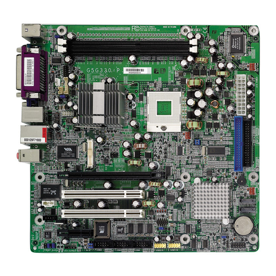
Hardware Installation Chapter 2 - Hardware Installation System Board Layout... -
Page 17: System Memory
Hardware Installation Warning: Electrostatic discharge (ESD) can damage your system board, proces- sor, disk drives, add-in boards, and other components. Perform the upgrade instruction procedures described at an ESD workstation only. If such a station is not available, you can provide some ESD protection by wearing an antistatic wrist strap and attaching it to a metal part of the system chassis. -
Page 18: Installing The Dim Module
Hardware Installation Installing the DIM Module A DIM module simply snaps into a DIMM socket on the system board. Pin 1 of the DIM module must correspond with Pin 1 of the socket. Notch Pin 1 1. Pull the “tabs” which are at the ends of the socket to the side. 2. -
Page 19: Cpu
Hardware Installation Overview The system board is equipped with a surface mount mPGA479M (Socket 479) CPU socket. This socket is exclusively designed for ® ® ® installing an Intel Pentium M / Celeron M processor. Installing the CPU 1. Make sure the PC and all other peripheral devices connected to it has been powered down. -
Page 20: Hardware Installation
Hardware Installation 5. Position the CPU above the socket. The gold triangular mark on the CPU must align with pin 1 of the CPU socket. Important: Handle the CPU by its edges and avoid touching the pins. Pin 1 of the socket Gold triangular mark... -
Page 21: Installing The Fan And Heat Sink
Hardware Installation Installing the Fan and Heat Sink The CPU must be kept cool by using a CPU fan with heat sink. Without sufficient air circulation across the CPU and heat sink, the CPU will overheat damaging both the CPU and system board. Note: •... - Page 22 Hardware Installation 2. Place the heat sink on top of the CPU. The 4 screws around the heat sink must match the screw holes of the retention module base. Refer to the figure below for the correct position of the heat sink.
-
Page 23: Jumper Settings
Hardware Installation Jumper Settings Clear CMOS Data 1-2 On: Normal (default) 2-3 On: Clear CMOS Data If you encounter the following, a) CMOS data becomes corrupted. b) You forgot the supervisor or user password. you can reconfigure the system with the default values stored in the ROM BIOS. - Page 24 Hardware Installation PS/2 Power Select 1-2 On: 5V 2-3 On: 5VSB (default) JP1 is used to select the power of the PS/2 keyboard/mouse port. Selecting 5VSB will allow you to use the PS/2 keyboard or PS/2 mouse to wake up the system. BIOS Setting Configure the PS/2 keyboard/mouse wake up function in the Integrated Peripherals submenu (“Super IO Device”...
-
Page 25: Usb Power Select
Hardware Installation USB Power Select USB 1-4 (JP2) 1-2 On: 5V 2-3 On: 5VSB (default) USB 5-8 1-2 On: 5V 2-3 On: 5VSB (JP5) (default) JP2 and JP5 are used to select the power of the USB ports. Selecting 5VSB will allow you to use the USB keyboard or USB mouse to wake up the system. -
Page 26: Lcd/Inverter Settings
Hardware Installation LCD/Inverter Settings JP3 is used to select the power supplied to the LCD panel and to configure the inverter. LCD/Inverter Settings - JP3 Panel Power Inverter On Level Inverter On/Off Select 1-3 On 2-4 On Active Low 8-10 On 3.3V 3-5 On 4-6 On... - Page 27 Hardware Installation LCD Brightness Control (Voltage Level Adjust) 1-2 On: Increases the voltage level 2-3 On: Decreases the voltage level Use J4 to connect to the LCD Brightness Control button of the LCD Display Panel. It is used to adjust the brightness of the LCD Display Panel.
- Page 28 Hardware Installation COM 4 RS232/RS485/AUX Select JP6 is used to set COM 4 to RS-232 or RS-485. If the serial device connected to this port requires 5V/12V power from the system board, set JP6 pins 1-3, 2-4, 9-11 and 10-12 to On. This setting automatically sets COM 4 at RS-232.
- Page 29 Hardware Installation COM 2 RS232/AUX Select 1-3, 2-4 On: 3-5 (5V), RS232 4-6 (12V) On: (default) Auxiliary power COM 2 is an RS-232 port. If the serial device connected to this port requires 5V/12V power from the system board, set JP4 pins 3-5 and 4-6 to On.
- Page 30 Hardware Installation Power-on Select 2-3 On: 1-2 On: Power-on via Power-on via power button AC power (default) JP8 is used to select the method of powering on the system. If you want the system to power-on whenever AC power comes in, set JP8 pins 1 and 2 to On.
- Page 31 Hardware Installation Pentium M Processor FSB Select 1-3, 2-4 On: 4-6 On: 3-5, 4-6 On: Dothan-B step Dothan-A step Dothan-A step FSB400 FSB533 ® JP7 is used to select the front side bus of a Pentium M processor. Important: Overclocking may result to the CPU’s or system’s instability and are not guaranteed to provide better system performance.
-
Page 32: Rear Panel I/O Ports
Hardware Installation Rear Panel I/O Ports PS/2 Mouse Parallel 1394_1 Mic-in Line-in Line-out PS/2 KB COM 1 USB 1-2 USB 3-4 The rear panel I/O ports consist of the following: • PS/2 mouse port • PS/2 keyboard port • Parallel port •... - Page 33 Hardware Installation PS/2 Mouse and PS/2 Keyboard Ports PS/2 Mouse PS/2 Keyboard The system board is equipped with an onboard PS/2 mouse (Green) and PS/2 keyboard (Purple) ports - both at location CN1 of the system board. The PS/2 mouse port uses IRQ12. If a mouse is not connected to this port, the system will reserve IRQ12 for other expansion cards.
- Page 34 Hardware Installation • BIOS Setting: Configure the PS/2 wake up function in the Integrated Peripherals submenu (“Super IO Device” section) of the BIOS. Refer to chapter 3 for more information. Important: The 5VSB power source of your power supply must support ≥...
-
Page 35: Serial Ports
Hardware Installation Serial Ports COM 1 COM 2 COM 4 COM 3 The system board is equipped with an onboard serial port at location CN4 (COM 1). It is also equipped with three 9-pin connectors at locations J8 (COM 2), J11 (COM 3) and J12 (COM 4). - Page 36 Hardware Installation Jumper Setting If the serial device connected to COM 2 and/or COM 4 requires auxiliar y power from the system board, set JP4 and/or JP6 appropriately. Refer to “COM 2 RS232/AUX Select” and “COM 4 RS232/RS485/AUX Select” in this chapter for more information. BIOS Setting Configure the serial ports in the Integrated Peripherals submenu of the BIOS.
-
Page 37: Parallel Port
Hardware Installation Parallel Port Parallel The system board has a standard parallel port (Burgundy) at loca- tion CN7 for interfacing your PC to a parallel printer. It supports SPP, ECP and EPP. Setting Function Allows normal speed operation but (Standard Parallel Port) in one direction only. -
Page 38: Vga Port
Hardware Installation VGA Port The system board can only be used with an analog video monitor. Connect the monitor’s 15-pin D-shell cable connector to the VGA port (Blue) at location CN2. If your monitor supports analog video but does not have a 15-pin D-shell connector, see your monitor dealer for the adapter or optional cable. - Page 39 Hardware Installation IEEE 1394 1394_1 1394_2 1 2 The system board is equipped with an onboard IEEE 1394 port at location CN6 (IEEE 1394_1) of the system board. It is also equipped with an IEEE 1394 connector at location J5 (IEEE 1394_2) for connecting an additional 1394 device.
- Page 40 Hardware Installation RJ45 Fast-Ethernet Port The system board is equipped with an onboard RJ45 LAN port at location CN5. This port allows the system board to connect to a local area network by means of a network hub. BIOS Setting Enable or disable the onboard LAN in the Integrated Peripherals submenu (“Onboard Device”...
-
Page 41: Universal Serial Bus Connectors
Hardware Installation Universal Serial Bus Connectors USB 2 USB 1 USB 4 USB 3 USB 5-6 USB 7-8 The system board supports 8 USB 2.0/1.1 ports. USB allows data exchange between your computer and a wide range of simultaneously accessible external Plug and Play peripherals. The 4 onboard USB 2.0/1.1 ports (Black) are at locations CN5 (USB 3-4) and CN6 (USB 1-2). - Page 42 Hardware Installation Driver Installation You may need to install the proper drivers in your operating system to use the USB device. Refer to your operating system’s manual or documentation for more information. If you are using a USB 2.0 device, install the “Intel USB 2.0 Drivers”. Refer to chapter 4 for more information.
-
Page 43: Audio (Rear Audio And Front Audio)
Hardware Installation Audio (Rear Audio and Front Audio) Mic-in Line-in Rear audio Line-out Front audio Rear Audio The system board is equipped with 3 audio jacks at location CN3. A jack is a one-hole connecting interface for inserting a plug. •... - Page 44 Hardware Installation 2-channel 6-channel 4-channel Light Blue Line-in Rear R/L Rear R/L Lime Line-out Front R/L Front R/L Pink Mic-in Center/Subwoofer Mic-in Front Audio The front audio connector (J1) allows you to connect to the line-out and mic-in jacks that are at the front panel of your system. Using the line-out and mic-in jacks will disable the rear audio’s line-out and mic- in functions.
-
Page 45: I/O Connectors
Hardware Installation I/O Connectors CD-in Internal Audio Connector Ground Ground Left audio Right audio channel channel The CD-in connector at location J3 is used to receive audio from a CD-ROM drive, TV tuner or MPEG card. - Page 46 Hardware Installation S/PDIF Connector SPDIF out SPDIF in The S/PDIF connector is used to connect external S/PDIF ports. Your S/PDIF ports may be mounted on a card-edge bracket. Install the card-edge bracket to the system chassis then connect the audio cable connector to SPDIF1.
- Page 47 Hardware Installation LVDS LCD Panel, LCD/Inverter Power and LCD AUX Power Connectors LCD AUX Power LVDS LCD Panel LCD/Inverter Power The system board allows you to connect a LCD Display Panel by means of the LVDS LCD panel connector (J7) and the LCD/Inverter power connector (J6).
- Page 48 Hardware Installation LVDS LCD Panel Connector Pins Pins Function Function N. C. N. C. N. C. N. C. LVDS_Out2+ LVDS_Out6+ LVDS_Out2- LVDS_Out6- LVDS_Out5+ LVDS_Out1+ LVDS_Out5- LVDS_Out1- LVDS_Out0+ LVDS_Out4+ LVDS_Out0- LVDS_Out4- LVDS_CLK2+ LVDS_CLK1+ LVDS_CLK2- LVDS_CLK1- COM3_TD COM3_DTR COM3_RTS COM3_RI COM3_DSR COM3_RD COM3_DCD COM3_CTS LCD/Inverter Power Connector...
-
Page 49: Floppy Disk Drive Connector
Hardware Installation Floppy Disk Drive Connector The system board is equipped with a shrouded floppy disk drive connector for connecting standard floppy disk drives. To prevent im- proper floppy cable installation, the shrouded floppy disk header has a keying mechanism. The 34-pin connector on the floppy cable can be placed into the header only if pin 1 of the connector is aligned with pin 1 of the header. -
Page 50: Serial Ata Connectors
Hardware Installation Serial ATA Connectors SATA 2 SATA 1 The system board is equipped with two Serial ATA connectors for connecting Serial ATA devices. Connect one end of the Serial ATA cable to SATA 1 or SATA 2 and the other end to your Serial ATA device. -
Page 51: Ide Disk Drive Connectors
Hardware Installation IDE Disk Drive Connectors The system board is equipped with a shrouded PCI IDE header that will interface two Enhanced IDE (Integrated Drive Electronics) disk drives. To prevent improper IDE cable installation, the shrouded PCI IDE header has a keying mechanism. The 40-pin connector on the IDE cable can be placed into the header only if pin 1 of the connector is aligned with pin 1 of the header. - Page 52 Hardware Installation Adding a Second IDE Disk Drive When using two IDE drives, one must be set as the master and the other as the slave. Follow the instructions provided by the drive manufacturer for setting the jumpers and/or switches on the drives. The system board suppor ts Enhanced IDE or ATA-2, ATA/33, ATA/66 and ATA/100 hard drives.
-
Page 53: Irda Connector
Hardware Installation IrDA Connector IRRX N. C. Ground IRTX Connect your IrDA cable to connector J10 on the system board. Note: The sequence of the pin functions on some IrDA cable may be reversed from the pin function defined on the system board. Make sure to connect the cable to the IrDA connector according to their pin functions. -
Page 54: Cooling Fan Connectors
Hardware Installation Cooling Fan Connectors Sense Power Ground 2nd fan Sense Power Ground CPU fan Sense Power Ground Chassis fan Connect the CPU fan’s cable connector to the CPU fan connector (J15) on the system board. The 2nd fan (J21) and chassis fan (J22) connectors are used to connect additional cooling fans. - Page 55 Hardware Installation Chassis Open Connector Chassis Ground signal The system board supports the chassis intrusion detection function. Connect the chassis intrusion sensor cable from the chassis to the chassis open connector. Whenever a chassis component has been removed, the sensor sends signal to the connector alerting you of a chassis intrusion event.
-
Page 56: Power Connectors
Hardware Installation Power Connectors 3.3V 3.3V -12V 3.3V Ground Ground PS-ON Ground Ground Ground Ground Ground PW-OK 5VSB +12V Use a power supply that complies with the ATX12V Power Supply Design Guide Version 1.1. An ATX12V power supply has a standard 20-pin ATX main power connector that must be inserted onto the J19 connector. - Page 57 Hardware Installation DIMM and PCI Standby Power LEDs DIMM Standby Power LED PCI Standby Power LED DIMM Standby Power LED This LED will turn red when the system’s power is on or when it is in the Suspend state (Power On Suspend or Suspend to RAM). It will not light when the system is in the Soft-Off state.
-
Page 58: Front Panel Connectors
Hardware Installation Front Panel Connectors RESET SW HDD-LED PWR-LED PWR-BTN HDD-LED - HDD LED This LED will light when the hard drive is being accessed. RESET SW - Reset Switch This switch allows you to reboot without having to power off the system. - Page 59 Hardware Installation PCI Express x16 and x1 Slots PCI Express x16 PCI Express x1 The system board is equipped with one PCI Express x16 and one PCI Express x1 slots. PCI Express x16 Install PCI Express x16 graphics card, that comply to the PCI Express specifications, into the PCI Express x16 slot.
-
Page 60: Chapter 3 - Bios Setup
BIOS Setup Chapter 3 - BIOS Setup Award BIOS Setup Utility The Basic Input/Output System (BIOS) is a program that takes care of the basic level of communication between the processor and peripherals. In addition, the BIOS also contains codes for various advanced features found in this system board. -
Page 61: Bios Setup
BIOS Setup Standard CMOS Features Use the arrow keys to highlight “Standard CMOS Features” and press <Enter>. A screen similar to the one below will appear. The settings on the screen are for reference only. Your version may not be identical to this one. - Page 62 BIOS Setup IDE Channel 0 Master/Slave and IDE Channel 1 Master/Slave Move the cursor to the “IDE Channel 0 Master”, “IDE Channel 0 Slave”, “IDE Channel 1 Master” or “IDE Channel 1 Slave” field, then press <Enter>. The settings on the screen are for reference only. Your version may not be identical to this one.
- Page 63 BIOS Setup Access Mode For hard drives larger than 528MB, you would typically select the LBA type. Certain operating systems require that you select CHS or Large. Please check your operating system’s manual or Help desk on which one to select. Capacity Displays the approximate capacity of the disk drive.
- Page 64 BIOS Setup Video This field selects the type of video adapter used for the primary system monitor. Although secondary monitors are supported, you do not have to select the type. The default setting is EGA/VGA. EGA/VGA Enhanced Graphics Adapter/Video Graphics Array. For EGA, VGA, SVGA and PGA monitor adapters.
- Page 65 BIOS Setup Extended Memory Displays the amount of extended memory detected during boot-up. Total Memory Displays the total memory available in the system.
-
Page 66: Advanced Bios Features
BIOS Setup Advanced BIOS Features The Advanced BIOS Features allows you to configure your system for basic operation. Some entries are defaults required by the system board, while others, if enabled, will improve the performance of your system or let you set some features according to your preference. The screen above list all the fields available in the Advanced BIOS Features submenu, for ease of reference in this manual. - Page 67 BIOS Setup CPU Feature Move the cursor to this field and press <Enter>. The following screen will appear. The settings on the screen are for reference only. Your version may not be identical to this one. Delay Prior To Thermal This field is used to select the time that would force the CPU to a 50% duty cycle when it exceeds its maximum operating temperature therefore protecting the CPU and the system board from...
- Page 68 BIOS Setup TM2 Bus VID This field is used to select the voltage of the throttled performance state that will be initiated when the on-die sensor turns from cool to hot. Execute Disable Bit When this field is set to Disabled, it will force the XD feature flag to always return to 0.
- Page 69 BIOS Setup CPU L1 & L2 Cache These fields speed up the memory access. The default value is enabled. Enable the external cache for better performance. CPU L3 Cache This field is used to enable or disable the CPU’s L3 cache. Quick Power On Self Test This field speeds up Power On Self Test (POST) whenever the system is powered on.
- Page 70 BIOS Setup Boot Up NumLock Status This allows you to determine the default state of the numeric keypad. By default, the system boots up with NumLock on wherein the function of the numeric keypad is the number keys. When set to Off, the function of the numeric keypad is the arrow keys.
- Page 71 BIOS Setup Security Option This field determines when the system will prompt for the password - everytime the system boots or only when you enter the BIOS setup. Set the password in the Set Supervisor/User Password submenu. System The system will not boot and access to Setup will be denied unless the correct password is entered at the prompt.
-
Page 72: Advanced Chipset Features
BIOS Setup Advanced Chipset Features The screen above list all the fields available in the Advanced Chipset Features submenu, for ease of reference in this manual. In the actual CMOS setup, you have to use the scroll bar to view the fields. The settings on the screen are for reference only. - Page 73 BIOS Setup select the best option in the “CAS Latency Time” to “System Memory Frequency” fields. CAS Latency Time This field is used to select the latency between the DRAM read command and the time that the data was received. DRAM RAS# to CAS# Delay This field is used to select the latency between the DRAM active command and the read/write command.
- Page 74 BIOS Setup Memory Hole At 15M-16M In order to improve system performance, certain space in memory can be reserved for ISA cards. This memory must be mapped into the memory space below 16MB. When enabled, the CPU assumes the 15- 16MB memory range is allocated to the hidden ISA address range instead of the actual system DRAM.
- Page 75 BIOS Setup PEG/Onchip VGA Control This field is used to select the graphics controller that will serve as the primary boot device. The options are Auto, Onchip VGA and PEG Port. PEG Force X1 The options are Enabled and Disabled. On-Chip Frame Buffer Size This field is used to select the onboard VGA’s frame buffer size that is shared from the system memory.
- Page 76 BIOS Setup Panel Number Panel 1 640x480, one channel 18-bit, LVDS Panel 2 800x600, one channel 18-bit, LVDS Panel 3 1024x768, one channel 18-bit, LVDS Panel 4 1280x1024, two channel 36-bit, LVDS If you are using one of the standard panels shown above, select the appropriate option according to the type of panel that you are using.
-
Page 77: Integrated Peripherals
BIOS Setup Integrated Peripherals The settings on the screen are for reference only. Your version may not be identical to this one. OnChip IDE Device Move the cursor to this field and press <Enter>. The following screen will appear. The settings on the screen are for reference only. Your version may not be identical to this one. - Page 78 BIOS Setup IDE HDD Block Mode Enabled The IDE HDD uses the block mode. The system BIOS will check the hard disk drive for the maxi- mum block size the system can transfer. The block size will depend on the type of hard disk drive. Disabled The IDE HDD uses the standard mode.
- Page 79 BIOS Setup On-Chip Serial ATA Setting On-Chip Serial ATA Disabled Disables the onboard SATA. Auto The system will detect the existing SATA and IDE drives then automatically set them to the available master/slave mode. Combined Mode This option allows you to use both IDE and SATA drives;...
- Page 80 BIOS Setup Onboard Device Move the cursor to this field and press <Enter>. The following screen will appear. The settings on the screen are for reference only. Your version may not be identical to this one. USB Controller Enabled Enables the onboard USB. Disabled Disables the onboard USB.
- Page 81 BIOS Setup USB Mouse Support This field is used to enable or disable the USB mouse. AC97 Audio Auto Select this option when using the onboard audio CODEC. Disabled Select this option when using a PCI sound card. Onboard LAN Control This field is used to enable or disable the onboard LAN.
- Page 82 BIOS Setup Super IO Device Move the cursor to this field and press <Enter>. The following screen will appear. The settings on the screen are for reference only. Your version may not be identical to this one. Power On Function This field allows you to use the keyboard or PS/2 mouse to power- on the system.
- Page 83 BIOS Setup KB Power On Password Move the cursor to this field and press <Enter>. Enter your pass- word. You can enter up to 5 characters. Type in exactly the same password to confirm, then press <Enter>. The power button will not function once a keyboard password has been set in this field.
- Page 84 BIOS Setup EPP Mode Select This field is used to select the EPP mode. ECP Mode Use DMA This is used to select a DMA channel of the parallel port. PWRON After PWR-Fail When power returns after an AC power failure, the system’s power is off.
- Page 85 BIOS Setup Onboard Serial Port 3 This is used to select an I/O address for the onboard serial port 3. However, if the LCD Display Panel supports touch screen, leave this field in its default setting because the touch screen is internally connected to COM 3 therefore a default address has already been assigned to this port.
-
Page 86: Power Management Setup
BIOS Setup Power Management Setup The Power Management Setup allows you to configure your system to most effectively save energy. The settings on the screen are for reference only. Your version may not be identical to this one. ACPI Function This function should be enabled only in operating systems that sup- ®... - Page 87 BIOS Setup Power Management This field allows you to select the type (or degree) of power saving by changing the length of idle time that elapses before the Suspend mode and HDD Power Down fields are activated. Min Saving Minimum power saving time for the Suspend Mode (1 hour) and HDD Power Down (15 min.) Max Saving Maximum power saving time for the.
- Page 88 BIOS Setup Suspend Mode This is selectable only when the Power Management field is set to User Define. When the system enters the Suspend mode according to the power saving time selected, the CPU and onboard peripherals will be shut off. HDD Power Down This is selectable only when the Power Management field is set to User Define.
- Page 89 BIOS Setup Wake-Up By PCI Card Enabled This field should be set to Enabled only if your PCI card such as LAN card or modem card uses the PCI PME (Power Management Event) signal to remotely wake up the system. Access to the LAN card or PCI card will cause the system to wake up.
- Page 90 BIOS Setup Time (hh:mm:ss) Alarm This is used to set the time you would like the system to power-on. If you want the system to power-on everyday as set in the “Date (of Month) Alarm” field, the time set in this field must be later than the time of the RTC set in the Standard CMOS Features submenu.
- Page 91 BIOS Setup PnP/PCI Configurations This section describes configuring the PCI bus system. It covers some very technical items and it is strongly recommended that only experienced users should make any changes to the default settings. The settings on the screen are for reference only. Your version may not be identical to this one.
- Page 92 BIOS Setup Resources Controlled By The Award Plug and Play BIOS has the capability to automatically configure all of the boot and Plug and Play compatible devices. Auto The system will automatically detect the settings for you. Manual Choose the specific IRQ in the “IRQ Resources” field respectively.
-
Page 93: Pc Health Status
BIOS Setup PC Health Status The settings on the screen are for reference only. Your version may not be identical to this one. Current System Temp., Current CPU Temperature, Current Chassis Fan Speed, Current CPU Fan Speed and Current 2nd Fan Speed These fields will show the internal temperature of the system, current temperature of the CPU, and the current fan speed of the cooling fans in RPM (Revolutions Per Minute). - Page 94 BIOS Setup Frequency/Voltage Control The settings on the screen are for reference only. Your version may not be identical to this one. Auto Detect PCI Clk When enabled, the system will automatically send clock signals to existing PCI devices. Spread Spectrum Leave this field in its default setting.
- Page 95 BIOS Setup Load Fail-Safe Defaults The “Load Fail-Safe Defaults” option loads the troubleshooting default values permanently stored in the ROM chips. These settings are not optimal and turn off all high performance features. You should use these values only if you have hardware problems. Highlight this option in the main menu and press <Enter>.
-
Page 96: Load Optimized Defaults
BIOS Setup Load Optimized Defaults The “Load Optimized Defaults” option loads optimized settings from the BIOS ROM. Use the default values as standard values for your system. Highlight this option in the main menu and press <Enter>. Type <Y> and press <Enter> to load the Setup default values. -
Page 97: Set Supervisor Password
BIOS Setup Set Supervisor Password If you want to protect your system and setup from unauthorized entry, set a supervisor’s password with the “System” option selected in the Advanced BIOS Features. If you want to protect access to setup only, but not your system, set a supervisor’s password with the “Setup”... - Page 98 BIOS Setup Set User Password If you want another user to have access only to your system but not to setup, set a user’s password with the “System” option se- lected in the Advanced BIOS Features. If you want a user to enter a password when trying to access setup, set a user’s password with the “Setup”...
- Page 99 BIOS Setup Save & Exit Setup When all the changes have been made, highlight “Save & Exit Setup” and press <Enter>. Type “Y” and press <Enter>. The modifications you have made will be written into the CMOS memory, and the system will reboot. You will once again see the initial diagnostics on the screen.
-
Page 100: Exit Without Saving
BIOS Setup Exit Without Saving When you do not want to save the changes you have made, highlight “Exit Without Saving” and press <Enter>. Type “Y” and press <Enter>. The system will reboot and you will once again see the initial diagnostics on the screen. If you wish to make any changes to the setup, press <Ctrl>... -
Page 101: Updating The Bios
BIOS Setup Updating the BIOS To update the BIOS, you will need the new BIOS file and a flash utility, AWDFLASH.EXE. Please contact technical support or your sales representative for the files. 1. Save the new BIOS file along with the flash utility AWDFLASH.EXE to a floppy disk. - Page 102 BIOS Setup 6. The following will appear. Do You Want to Save BIOS (Y/N) This question refers to the current existing BIOS in your system. We recommend that you save the current BIOS and its flash utility; just in case you need to reinstall the BIOS. To save the current BIOS, press <Y>...
-
Page 103: Chapter 4 - Supported Softwares
Supported Software Chapter 4 - Supported Software Drivers, Utilities and Software Applications The CD that came with the system board contains drivers, utilities and software applications required to enhance the performance of the system board. Insert the CD into a CD-ROM drive. The autorun screen (Main Board Utility CD) will appear. -
Page 104: Supported Software
Supported Software Intel Chipset Software Installation Utility The Intel Chipset Software Installation Utility is used for updating Windows INF files so that the Intel chipset can be recognized and configured properly in the system. To install the utility, please follow the steps below. 1. -
Page 105: Intel Graphics Drivers
Supported Software Intel Graphics Drivers To install the driver, please follow the steps below. 1. Click “Intel Graphics Drivers” on the main menu. The following screen will appear. 2. Follow the prompts on the screen to complete installation. 3. Reboot the system for the driver to take effect. -
Page 106: Audio Drivers
Supported Software Audio Drivers To install the driver, please follow the steps below. 1. Click “Audio Drivers” on the main menu. The following screen will appear. 2. Follow the prompts on the screen to complete installation. 3. Reboot the system for the driver to take effect. -
Page 107: Lan Drivers
Supported Software LAN Drivers To install the driver, please follow the steps below. 1. Click “LAN Drivers” on the main menu. The following screen will appear. 2. Follow the prompts on the screen to complete installation. 3. Reboot the system for the driver to take effect. -
Page 108: Hardware Monitor For Windows
Supported Software Hardware Monitor for Windows Hardware Monitor for Windows is capable of monitoring the system’s hardware conditions such as the temperature of the CPU and system, voltage, and speed of the cooling fans. It also allows you to manually set a range to the items being monitored. If the values are over or under the set range, a warning message will pop-up. - Page 109 Supported Software Microsoft DirectX 9 Driver To install, please follow the steps below. 1. Click “Microsoft DirectX 9 Driver” on the main menu. The following screen will appear. 2. Click “I accept the agreement” then click “Next”. 3. Follow the prompts on the screen to complete installation. 4.
-
Page 110: Installation Notes
Supported Software Intel USB 2.0 Drivers The Intel chipset does not support USB 2.0 drivers for Windows 98 SE and Windows ® Windows ® If your Windows XP CD already includes Service Pack 1, the USB 2.0 driver will automatically install when you install the operating system. -
Page 111: Watchdog Timer
Watchdog Timer Appendix A - Watchdog Timer Watchdog Timer The following parameters are references for setting the time interval of the Watchdog Timer function. The system will regularly be “cleared” according to the set time interval. If the system hangs or fails to function, it will also reset according to the time interval so that your system will continue to operate. -
Page 112: Appendix B - System Error Messages
System Error Message Appendix B - System Error Message When the BIOS encounters an error that requires the user to correct something, either a beep code will sound or a message will be displayed in a box in the middle of the screen and the message, PRESS F1 TO CONTINUE or DEL TO ENTER SETUP, will be shown in the information box at the bottom. - Page 113 System Error Message setting than indicated in Setup. Determine which setting is correct, either turn off the system and change the jumper or enter Setup and change the VIDEO selection. FLOPPY DISK(S) fail (80) Unable to reset floppy subsystem. FLOPPY DISK(S) fail (40) Floppy type mismatch.
-
Page 114: Appendix C - Troubleshooting
Troubleshooting Appendix C - Troubleshooting Troubleshooting Checklist This chapter of the manual is designed to help you with problems that you may encounter with your personal computer. To efficiently troubleshoot your system, treat each problem individually. This is to ensure an accurate diagnosis of the problem in case a problem has multiple causes. -
Page 115: Power Supply
Troubleshooting The picture seems to be constantly moving. 1. The monitor has lost its vertical sync. Adjust the monitor’s vertical sync. 2. Move away any objects, such as another monitor or fan, that may be creating a magnetic field around the display. 3. -
Page 116: Hard Drive
Troubleshooting Hard Drive Hard disk failure. 1. Make sure the correct drive type for the hard disk drive has been entered in the BIOS. 2. If the system is configured with two hard drives, make sure the bootable (first) hard drive is configured as Master and the second hard drive is configured as Slave. -
Page 117: Serial Port
Troubleshooting Serial Port The serial device (modem, printer) doesn’t output anything or is outputting garbled characters. 1. Make sure that the serial device’s power is turned on and that the device is on-line. 2. Verify that the device is plugged into the correct serial port on the rear of the computer.
Need help?
Do you have a question about the G5G330-P and is the answer not in the manual?
Questions and answers