Table of Contents
Advertisement
Quick Links
Advertisement
Table of Contents
Troubleshooting

Related Manuals for DFI G5C100-B


Summary of Contents for DFI G5C100-B
-
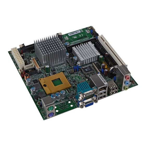
Page 1: System Board
G5C100-B System Board User’s Manual 935-G5C104-300G A01610805... - Page 2 Copyright This publication contains information that is protected by copyright. No part of it may be reproduced in any form or by any means or used to make any transformation/adaptation without the prior writ- ten permission from the copyright holders. This publication is provided for informational purposes only.
-
Page 3: Fcc And Doc Statement On Class B
FCC and DOC Statement on Class B This equipment has been tested and found to comply with the limits for a Class B digital device, pursuant to Part 15 of the FCC rules. These limits are designed to provide reasonable protection against harmful interference when the equipment is operated in a residential installation. -
Page 4: Table Of Contents
Table of Contents About this Manual................Warranty....................Static Electricity Precaution..............Safety Measures..................About the Package................Before Using the System Board............Chapter 1 - Introduction..............Specifications........................... Special Features of the System Board..............Chapter 2 - Hardware Installation............ System Board Layout ......................System Memory.......................... -
Page 5: About This Manual
About this Manual An electronic file of this manual is included in the CD. To view the user’s manual in the CD, insert the CD into a CD-ROM drive. The autorun screen (Main Board Utility CD) will appear. Click “User’s Manual”... -
Page 6: Static Electricity Precaution
Introduction Static Electricity Precautions It is quite easy to inadvertently damage your PC, system board, components or devices even before installing them in your system unit. Static electrical discharge can damage computer components without causing any signs of physical damage. You must take extra care in handling them to ensure against electrostatic build-up. -
Page 7: About The Package
Introduction About the Package The system board package contains the following items. If any of these items are missing or damaged, please contact your dealer or sales representative for assistance. The system board A user’s manual One IDE cable One bracket mounted with 2 USB ports One Serial ATA data cable One Serial ATA power cable One “Main Board Utility”... -
Page 8: Chapter 1 - Introduction
Introduction Chapter 1 - Introduction Specifications Processor • Intel Core Duo/Solo processor ® Intel Core 2 Duo processor ® - 667MHz/533MHz system data bus • Intel Celeron M processor ® ® - 533MHz system data bus (on Ultra Low Voltage) •... - Page 9 Introduction • Supports up to two IDE devices • Supports Ultra ATA 100/66/33 Rear Panel I/O • 1 mini-DIN-6 PS/2 mouse port Ports • 1 mini-DIN-6 PS/2 keyboard port • 1 DB-9 serial port • 1 DB-15 VGA port • 1 RJ45 LAN port •...
-
Page 10: Special Features Of The System Board
Introduction Features The Watchdog Timer function allows your watchdog timer application to regularly “clear” the system at the set time interval. If the system hangs or fails to function, it will reset at the set time interval so that your system will continue to operate. - Page 11 Introduction The Marvell 88E8053 Gigabit LAN chip supports gigabit lan up to 1Gbps data transmission. The system board is equipped with an IrDA connec- irda tor for wireless connectivity between your computer and peripheral devices. The IRDA (Infrared Data Association) specifi- cation supports data transfers of 115K baud at a distance of 1 meter.
- Page 12 Introduction Important: The 5V_standby power source of your power supply must sup- port ≥ 720mA. This function allows you to use a USB key- wake-on-USB board or USB mouse to wake up a system from the S3 (STR - Suspend To RAM) state. Important: If you are using the Wake-On-USB Keyboard/Mouse function for 2 USB ports, the 5V_standby power source of your power sup-...
- Page 13 Introduction When power returns after an AC power fail- Power failure ure, you may choose to either power-on the recovery system manually or let the system power-on automatically.
-
Page 14: Chapter 2 - Hardware Installation
Hardware Installation Chapter 2 - Hardware Installation System Board Layout... -
Page 15: System Memory
Hardware Installation Warning: Electrostatic discharge (ESD) can damage your system board, proces- sor, disk drives, add-in boards, and other components. Perform the upgrade instruction procedures described at an ESD workstation only. If such a station is not available, you can provide some ESD protec- tion by wearing an antistatic wrist strap and attaching it to a metal part of the system chassis. -
Page 16: Hardware Installation
Hardware Installation The system board is equipped with 2 SODIMM sockets. SODIMM 1 is a 90 socket located beneath SODIMM 2. SODIMM 2 SODIMM 1 The two DDR2 SODIMM sockets on the system board are divided into 2 channels: Channel A - SODIMM 1 Channel B - SODIMM 2 The system board supports the following memory interface. -
Page 17: Installing The Memory Module
Hardware Installation Installing the Memory Module 1. Make sure the PC and all other peripheral devices connected to it has been powered down. 2. Disconnect all power cords and cables. 3. Locate the SODIMM 2 socket on the system board. 4. - Page 18 Hardware Installation 7. To install another SODIMM, locate the SODIMM 1 socket on the system board. 8. Insert the module into the socket at an approximately 30 de- grees angle. Note that the socket and module are both keyed, which means the module can be plugged into the socket in only one way.
-
Page 19: Cpu
Hardware Installation Overview The system board is equipped with a surface mount mPGA478 CPU socket. Installing the CPU 1. Make sure the PC and all other peripheral devices connected to it has been powered down. 2. Disconnect all power cords and cables. 3. - Page 20 Hardware Installation 5. Position the CPU above the socket. The gold triangular mark on the CPU must align with pin 1 of the CPU socket. Important: ® 1. Only Use Intel Core Duo/Solo processor or ® ® Intel Celeron M processor manufactured on 65nm technology.
- Page 21 Hardware Installation Installing the Fan and Heat Sink The CPU must be kept cool by using a CPU fan with heat sink. Without sufficient air circulation across the CPU and heat sink, the CPU will overheat damaging both the CPU and system board. Note: •...
- Page 22 Hardware Installation 2. Place the heat sink on top of the CPU. The 4 screws around the heat sink must match the screw holes of the retention module base. Refer to the figure below for the correct position of the heat sink.
- Page 23 Hardware Installation Important: When you install the CPU fan and heat sink assembly, make sure the assembly is positioned in such a way that the direc- tion of the airflow blows towards the Northbridge. This is to ensure optimum thermal condition and system performance.
-
Page 24: Jumper Settings
Hardware Installation Jumper Settings Clear CMOS Data 1-2 On: Normal (default) 2-3 On: Clear CMOS Data If you encounter the following, a) CMOS data becomes corrupted. b) You forgot the supervisor or user password. you can reconfigure the system with the default values stored in the ROM BIOS. - Page 25 Hardware Installation PS/2 Power Select 1-2 On: 5V 2-3 On: (default) 5V_standby JP8 is used to select the power of the PS/2 keyboard/mouse port. Selecting 5V_standby will allow you to use the PS/2 keyboard or PS/2 mouse to wake up the system. BIOS Setting Configure the PS/2 keyboard/mouse wake up function in the Inte- grated Peripherals submenu (“Super IO Device”...
-
Page 26: Usb Power Select
Hardware Installation USB Power Select USB 1-4 (JP6) 1-2 On: 5V 2-3 On: (default) 5V_standby USB 5-8 (JP5) 1-2 On: 5V 2-3 On: (default) 5V_standby JP6 (for USB 1-4) and JP5 (for USB 5-8) are used to select the power of the USB ports. Selecting 5V_standby will allow you to use a USB device to wake up the system. -
Page 27: Lcd/Inverter Settings
Hardware Installation LCD/Inverter Settings JP7 is used to select the power supplied to the LCD panel and to configure the inverter. LCD/Inverter Settings - JP7 Panel Power Inverter On Level Inverter On/Off Select 1-3 On 2-4 On Active Low 8-10 On 3.3V 3-5 On 4-6 On... - Page 28 Hardware Installation LCD Brightness Control (Voltage Level Adjust) 1-2 On: Increases the voltage level 2-3 On: Decreases the voltage level Use J7 to connect to the LCD Brightness Control button of the LCD Display Panel. It is used to adjust the brightness of the LCD Display Panel.
- Page 29 Hardware Installation COM 4 RS232/RS485/AUX Select JP11 JP11 is used to set COM 4 to RS-232 or RS-485. If the serial device connected to this port requires 5V/12V power from the sys- tem board, set JP11 pins 1-3, 2-4, 9-11 and 10-12 to On. COM 4 RS232/RS485/AUX Select JP11 RS232 (default)
- Page 30 Hardware Installation Power-on Select 1-2 On: Power-on via AC power 2-3 On: Power-on via power button (default) JP9 is used to select the method of powering on the system. If you want the system to power-on whenever AC power comes in, set JP9 pins 1 and 2 to On.
- Page 31 Hardware Installation Intel Core Duo/Solo, Core2 Duo CPU FSB Select Auto Detect 533MHz FSB Jumpers JP1, JP2 and JP3 are used to select the Front Side Bus of the CPU. Important: • If you are using a CPU whose frequency has been locked by the manufacturer, overclocking will have no effect.
-
Page 32: Rear Panel I/O Ports
Hardware Installation Rear Panel I/O Ports PS/2 COM 4 Mic-in Mouse USB 4 Line-in Line-out PS/2 K/B USB 1-2 USB 3 The rear panel I/O ports consist of the following: • PS/2 mouse port • PS/2 keyboard port • COM port •... - Page 33 Hardware Installation PS/2 Mouse and PS/2 Keyboard Ports PS/2 Mouse PS/2 Keyboard The system board is equipped with an onboard PS/2 mouse (Green) and PS/2 keyboard (Purple) ports - both at location CN8 of the system board. The PS/2 mouse port uses IRQ12. If a mouse is not connected to this port, the system will reserve IRQ12 for other expansion cards.
- Page 34 Hardware Installation • BIOS Setting: Configure the PS/2 wake up function in the Integrated Peripherals submenu (“Super IO Device” section) of the BIOS. Refer to chapter 3 for more information. Important: The 5V_standby power source of your power supply must sup- port ≥...
-
Page 35: Serial Ports
Hardware Installation Serial Ports COM 4 9 9 9 9 9 2 2 2 2 2 1 1 1 1 1 COM 3 The system board is equipped with an onboard serial port at location CN1 (COM 4). It is also equipped with a 9-pin connector at location J15 (COM 3). - Page 36 Hardware Installation Jumper Setting Use JP11 to set COM 4 to RS-232 or RS-485. Refer to “COM 4 RS232/RS485/AUX Select” in this chapter for more information. BIOS Setting Configure the serial ports in the Integrated Peripherals submenu (“Super IO Device” section) of the BIOS. Refer to chapter 3 for more information.
-
Page 37: Vga Port
Hardware Installation VGA Port The VGA port is used for connecting a VGA monitor. Connect the monitor’s 15-pin D-shell cable connector to the VGA port (Blue) at location CN1. After you plug the monitor’s cable connector into the VGA port, gently tighten the cable screws to hold the connector in place. - Page 38 Hardware Installation RJ45 Fast-Ethernet Port The onboard LAN port allows the system board to connect to a local area network by means of a network hub. BIOS Setting Configure the onboard LAN in the Integrated Peripherals submenu (“Onboard Device” section) of the BIOS. Refer to chapter 3 for more information.
-
Page 39: Universal Serial Bus Connectors
Hardware Installation Universal Serial Bus Connectors USB 2 USB 1 USB 4 USB 3 USB 7-8 USB 5-6 The system board supports 8 USB 2.0/1.1 ports. USB allows data exchange between your computer and a wide range of simultane- ously accessible external Plug and Play peripherals. Four onboard USB 2.0/1.1 ports (Black) are at locations CN4 (USB 1-2) and CN3 (USB 3-4) of the system board. - Page 40 Hardware Installation Driver Installation You may need to install the proper drivers in your operating system to use the USB device. Refer to your operating system’s manual or documentation for more information. Refer to chapter 4 for more information about installing the USB 2.0 driver.
- Page 41 Hardware Installation Audio Mic-in Line-in Line-out 1 0 9 AuD_L_Return AuD_L_Out N. C. AuD_R_Return AuD_R_Out AuD_Vcc Mic Power Front audio Audio Jacks The system board is equipped with 3 audio jacks at location CN5. A jack is a one-hole connecting interface for inserting a plug. •...
- Page 42 Hardware Installation Front Audio The front audio connector (J2) allows you to connect to the line-out and mic-in jacks that are at the front panel of your system. Using the line-out and mic-in jacks will disable the rear audio’s line-out and mic- in functions.
-
Page 43: I/O Connectors
Hardware Installation I/O Connectors CD-in Internal Audio Connector Right audio channel Ground Ground Left audio channel The CD-in connector (CDIN1) is used to receive audio from a CD- ROM drive, TV tuner or MPEG card. - Page 44 Hardware Installation S/PDIF-out Connector N.C. SPDIF out The S/PDIF-out connector (SPDIF1) is used to connect an external S/PDIF-out port. Your S/PDIF-out port may be mounted on a card- edge bracket. Install the card-edge bracket to an available slot at the rear of the system chassis then connect the audio cable connector to the S/PDIF-out connector.
- Page 45 Hardware Installation LVDS LCD Panel Connector LCD/Inverter Power Connector LCD AUX Power Connector LCD/Inverter Power LCD AUX Power LVDS LCD Panel The system board allows you to connect a LCD Display Panel by means of the LVDS LCD panel connector (CN7) and the LCD/ Inverter power connector (CN6).
- Page 46 Hardware Installation LVDS LCD Panel Connector Pins Function Pins Function LVDS_Out3+ LVDS_Out7+ LVDS_Out3- LVDS_Out7- LVDS_Out2+ LVDS_Out6+ LVDS_Out2- LVDS_Out6- LVDS_Out1+ LVDS_Out5+ LVDS_Out1- LVDS_Out5- LVDS_Out0+ LVDS_Out4+ LVDS_Out0- LVDS_Out4- LVDS_CLK1+ LVDS_CLK2+ LVDS_CLK1- LVDS_CLK2- COM3-(NDTR3-) COM3-(NTD3) COM3-(NRTS3-) COM3-(XRI3-) COM3-(NRD3) COM3-(NDSR3-) COM3-(NCTS3-) COM3-(NDCD3-) LCD/Inverter Power Connector Pins Function Pins...
- Page 47 Hardware Installation Digital I/O Connector The Digital I/O connector provides powering-on function of an exter- nal device that is connected to this connector. Digital I/O Connector Pins Function Pins Function +12V DIO7 +12V DIO6 DIO5 DIO4 DIO3 DIO2 V_5P0_STBY DIO1 V_5P0_STBY DIO0...
-
Page 48: Floppy Disk Drive Connector
Hardware Installation Floppy Disk Drive Connector The system board is equipped with a 26-pin FPC type floppy disk drive connector. Only connect a 1.44MB slim-type floppy disk drive. Floppy drives other than the one mentioned above are optional. Refer to the next page for the pin function of this connector. Connecting the Floppy Disk Drive Cable Install one end of the floppy disk drive cable into the floppy disk connector (FDC1) on the system board and the other end connec-... - Page 49 Hardware Installation FPC Type FDD Connector Pins Pins Function Function INDEX# DR0# DSKCH# N. C. N. C. MTR0# N. C. N. C. DIR# STEP# DRVDE0 WDATA# WGATE# TRK0# WRPRO# RDATA# HDSEL#...
-
Page 50: Serial Ata Connectors
Hardware Installation Serial ATA Connectors SATA 2 SATA 1 The system board is equipped with two Serial ATA connectors for connecting Serial ATA devices. Connect one end of the Serial ATA cable to SATA 1 or SATA 2 connector and the other end to your Serial ATA device. -
Page 51: Ide Disk Drive Connectors
Hardware Installation IDE Disk Drive Connectors The system board is equipped with a 40-pin IDE (IDE 1) connector for connecting 3.5” hard drives. To prevent improper IDE cable instal- lation, the IDE 1 connector has a keying mechanism. The connector on the IDE cable can be inserted into IDE 1 only if pin 1 of the cable connector is aligned with pin 1 of IDE 1. - Page 52 Hardware Installation Connecting the IDE Disk Drive Cable Install one end of the IDE cable into IDE 1 on the system board and the other connectors to the IDE devices. Note: Refer to your disk drive user’s manual for information about selecting proper drive switch settings.
-
Page 53: Irda Connector
Hardware Installation IrDA Connector IRTX Ground IRRX N. C. Connect your IrDA cable to the IR1 connector on the system board. Note: The sequence of the pin functions on some IrDA cable may be reversed from the pin function defined on the system board. Make sure to connect the cable to the IrDA connector accord- ing to their pin functions. -
Page 54: Cooling Fan Connectors
Hardware Installation Cooling Fan Connectors Power Ground Sense CPU fan Power Ground Sense System fan Connect the CPU fan’s cable connector to the CPU fan connector (J11) on the system board. The system fan connector (J9) is used to connect an additional cooling fan. The cooling fans will provide ad- equate airflow throughout the chassis to prevent overheating the CPU and system board components. - Page 55 Hardware Installation Chassis Open Connector Ground Chassis signal The system board supports the chassis intrusion detection function. Connect the chassis intrusion sensor cable from the chassis to J12. Whenever a chassis component has been removed, the sensor sends signal to J12 alerting you of a chassis intrusion event. To dis- able this function, place a jumper cap over J12.
-
Page 56: Power Connector
Hardware Installation Power Connector The 20-pin ATX main power connector must be inserted onto the P1 connector. The system board requires a minimum of 100 Watt power supply to operate. We recommend that you use a power supply that complies with the ATX12V Power Supply Design Guide Version 1.1. - Page 57 Hardware Installation DRAM Power LED and Standby Power LED DRAM Power LED Standby Power LED DRAM Power LED This LED will turn red when the system’s power is on or when it is in the Suspend state (Power On Suspend or Suspend to RAM). It will not light when the system is in the Soft-Off state.
-
Page 58: Front Panel Connectors
Hardware Installation Front Panel Connectors RESET SW HDD-LED PWR-LED PWR-BTN HDD-LED - HDD LED This LED will light when the hard drive is being accessed. RESET SW - Reset Switch This switch allows you to reboot without having to power off the system. - Page 59 Hardware Installation PCI Slot PCI Slot You can install a PCI expansion card or a customized riser card designed for 1, 2 or 3 PCI slots expansion (for low profile PCI card only) into the PCI slot.
- Page 60 Hardware Installation Battery Battery The lithium ion battery powers the real-time clock and CMOS memory. It is an auxiliary source of power when the main power is shut off. Safety Measures • Danger of explosion if battery incorrectly replaced. • Replace only with the same or equivalent type recommend by the manufacturer.
-
Page 61: Chapter 3 - Bios Setup
BIOS Setup Chapter 3 - BIOS Setup Award BIOS Setup Utility The Basic Input/Output System (BIOS) is a program that takes care of the basic level of communication between the processor and pe- ripherals. In addition, the BIOS also contains codes for various ad- vanced features found in this system board. -
Page 62: Standard Cmos Features
BIOS Setup Standard CMOS Features Use the arrow keys to highlight “Standard CMOS Features” and press <Enter>. A screen similar to the one below will appear. Phoenix - AwardBIOS CMOS Setup Utility Standard CMOS Features Mon, Jun 4 2007 Date <mm:dd:yy> Item Help Time <hh:mm:ss>... -
Page 63: Ide Hdd Auto Detection
BIOS Setup IDE Channel 0 Master, IDE Channel 0 Slave, IDE Channel 1 Master and IDE Channel 1 Slave To configure the IDE drives, move the cursor to a field then press <Enter>. The following screen will appear. Phoenix - AwardBIOS CMOS Setup Utility IDE Channel 0 Master IDE HDD Auto-Detection Press Enter... -
Page 64: Bios Setup
BIOS Setup Capacity Displays the approximate capacity of the disk drive. Usually the size is slightly greater than the size of a formatted disk given by a disk checking program. Cylinder This field displays the number of cylinders. Head This field displays the number of read/write heads. Precomp This field displays the number of cylinders at which to change the write timing. - Page 65 BIOS Setup Video This field selects the type of video adapter used for the primary system monitor. Although secondary monitors are supported, you do not have to select the type. The default setting is EGA/VGA. EGA/VGA Enhanced Graphics Adapter/Video Graphics Array. For EGA, VGA, SVGA and PGA monitor adapters.
- Page 66 BIOS Setup Extended Memory Displays the amount of extended memory detected during boot-up. Total Memory Displays the total memory available in the system.
-
Page 67: Advanced Bios Features
BIOS Setup Advanced BIOS Features The Advanced BIOS Features allows you to configure your system for basic operation. Some entries are defaults required by the system board, while others, if enabled, will improve the performance of your system or let you set some features according to your preference. Phoenix - AwardBIOS CMOS Setup Utility Advanced BIOS Features Item Help... - Page 68 BIOS Setup CPU Feature This field is used to configure the CPU that is installed on the sys- tem board. Move the cursor to this field then press <Enter>. Phoenix - AwardBIOS CMOS Setup Utility CPU Feature Delay Prior to Thermal 16 Min Item Help C1E Function...
-
Page 69: Hard Disk Boot Priority
BIOS Setup Hard Disk Boot Priority This field is used to select the boot sequence of the hard drives. Move the cursor to this field then press <Enter>. Use the Up or Down arrow keys to select a device then press <+> to move it up or <->... - Page 70 BIOS Setup Many disk diagnostic programs which attempt to access the boot sector table will cause the warning message to appear. If you are running such a program, we recommend that you first disable this field. Also, disable this field if you are installing or running certain operating systems like Windows 98/2000/ME/XP or the operating ®...
- Page 71 BIOS Setup Boot Up NumLock Status This allows you to determine the default state of the numeric keypad. By default, the system boots up with NumLock on wherein the function of the numeric keypad is the number keys. When set to Off, the function of the numeric keypad is the arrow keys.
- Page 72 BIOS Setup Security Option This field determines when the system will prompt for the password - everytime the system boots or only when you enter the BIOS setup. Set the password in the Set Supervisor/User Password submenu. System The system will not boot and access to Setup will be denied unless the correct password is entered at the prompt.
-
Page 73: Advanced Chipset Features
BIOS Setup Advanced Chipset Features Phoenix - AwardBIOS CMOS Setup Utility Advanced Chipset Features DRAM Timing Selectable By SPD Item Help CAS Latency Time Auto Menu Level DRAM RAS# to CAS# Delay Auto DRAM RAS# Precharge Auto Precharge Delay <tRAS> Auto System Memory Frequency Auto... - Page 74 BIOS Setup ble condition for the system. The “CAS Latency Time” and “Precharge Delay” fields will show the default settings by SPD. Manual If you want better performance for your system other than the one “by SPD”, select “Manual” then select the best option in the “CAS Latency Time”...
- Page 75 BIOS Setup Video BIOS Cacheable As with caching the system BIOS, enabling the Video BIOS cache will allow access to video BIOS addresssed at C0000H to C7FFFH to be cached, if the cache controller is also enabled. The larger the range of the Cache RAM, the faster the video performance.
- Page 76 BIOS Setup Boot Display This field is used to select the type of display to use when the system boots. Select this option if you want the system to boot the CRT display. Select this option if you want the system to boot the LCD flat panel display.
-
Page 77: Integrated Peripherals
BIOS Setup Integrated Peripherals Phoenix - AwardBIOS CMOS Setup Utility Integrated Peripherals Press Enter OnChip IDE Device Item Help Press Enter Onboard Device Menu Level Super IO Device Press Enter ↑↓→← : Move Enter: Select +/-/PU/PD: Value F10: Save ESC: Exit F1: General Help F5: Previous Values F6: Fail-Safe Defaults... - Page 78 BIOS Setup IDE HDD Block Mode Enabled The IDE HDD uses the block mode. The system BIOS will check the hard disk drive for the maximum block size the system can transfer. The block size will depend on the type of hard disk drive. Disabled The IDE HDD uses the standard mode.
- Page 79 BIOS Setup On-Chip Serial ATA Disabled Disables the onboard SATA. Auto The system will detect the existing SATA and IDE drives then automatically set them to the available master/slave mode. Combined Mode This option allows you to combine both IDE and SATA drives;...
-
Page 80: Onboard Device
BIOS Setup Onboard Device Move the cursor to this field and press <Enter>. The following screen will appear. Phoenix - AwardBIOS CMOS Setup Utility Onboard Device USB Controller Enabled Item Help Enabled USB 2.0 Controller Menu Level USB Keyboard Support Disabled AC97 Audio Auto... - Page 81 BIOS Setup AC97 Audio Auto Select this option when using the onboard audio codec. Disabled Select this option when using a PCI sound card. Onboard LAN 1 Control Auto The system automatically detects the onboard LAN Disabled Disables the onboard LAN 1.
-
Page 82: Power On Function
BIOS Setup Super IO Device Move the cursor to this field and press <Enter>. The following screen will appear. Phoenix - AwardBIOS CMOS Setup Utility Super IO Device Power On Function BUTTON ONLY Item Help Hot Key Power ON Ctrl-F1 Menu Level Onboard FDC Controller Enabled... - Page 83 BIOS Setup Hot Key Power On This field is used to select a function key that you would like to use to power-on the system. Onboard FDC Controller Enabled Enables the onboard floppy disk controller. Disabled Disables the onboard floppy disk controller. PWRON After PWR-Fail When power returns after an AC power failure, the system’s power is off.
- Page 84 BIOS Setup Onboard Serial Port 1, Onboard Serial Port 3 and Onboard Serial Port 4 3F8, 2F8, 3E8, 2E8 Allows you to manually select an I/O address for the serial port. Disabled Disables the serial por t. Note: The touch screen is internally connected to COM 3. If the LCD Display Panel supports touch screen, leave the “Onboard Serial Port 3”...
-
Page 85: Power Management Setup
BIOS Setup Power Management Setup The Power Management Setup allows you to configure your system to most effectively save energy. Phoenix - AwardBIOS CMOS Setup Utility Power Management Setup ACPI Function Enabled Item Help ACPI Suspend Type S1(POS) Menu Level Auto x Run VGABIOS if S3 Resumes User Define... - Page 86 BIOS Setup Run VGABIOS if S3 Resume When this field is set to Auto, the system will initialize the VGA BIOS when it wakes up from the S3 state. This can be configured only if the “ACPI Suspend Type” field is set to “S3(STR)”. Power Management This field allows you to select the type (or degree) of power saving by changing the length of idle time that elapses before the “Suspend...
- Page 87 BIOS Setup Suspend Mode When the system enters the Suspend mode, the CPU and onboard peripherals will be shut off. HDD Power Down This is selectable only when the Power Management field is set to User Define. When the system enters the HDD Power Down mode according to the power saving time selected, the hard disk drive will be powered down while all other devices remain active.
- Page 88 BIOS Setup Power On By Ring When this field is set to Enabled, the system will power-on to respond to calls coming from a modem. Refer to “Wake-On-Ring Connector” in chapter 2 for more information. USB KB Wake-Up From S3 This field, when enabled, allows you to use a USB keyboard or USB mouse to wake up a system that is in the S3 (STR - Suspend To RAM) state.
- Page 89 BIOS Setup PnP/PCI Configurations This section shows how to configure the PCI bus system. It covers some very technical items and it is strongly recommended that only experienced users should make any changes to the default settings. Phoenix - AwardBIOS CMOS Setup Utility PnP/PCI Configurations Reset Configuration Data Disabled...
-
Page 90: Resources Controlled By
BIOS Setup Resources Controlled By The Award Plug and Play BIOS has the capability to automatically configure all of the boot and Plug and Play compatible devices. Auto(ESCD) The system will automatically detect the settings for you. Manual Choose the specific IRQ resources in the “IRQ Re- sources”... -
Page 91: Pc Health Status
BIOS Setup PC Health Status Phoenix - AwardBIOS CMOS Setup Utility PC Health Status Current System Temp Item Help Current CPU Temperature Menu Level System Fan 0 RPM CPU Fan 1004 RPM Vcore 1.26V +12V 11.89V 4.88V +3.3V 3.32V VBAT (V) 3.00V 5VSB (V) 5.02V... -
Page 92: Spread Spectrum
BIOS Setup Frequency/Voltage Control Phoenix - AwardBIOS CMOS Setup Utility Frequency/Voltage Control Disabled Spread Spectrum Item Help Menu Level ↑↓→← : Move Enter: Select +/-/PU/PD: Value F10: Save ESC: Exit F1: General Help F5: Previous Values F6: Fail-Safe Defaults F7: Optimized Defaults The settings on the screen are for reference only. -
Page 93: Load Fail-Safe Defaults
BIOS Setup Load Fail-Safe Defaults The “Load Fail-Safe Defaults” option loads the troubleshooting de- fault values permanently stored in the ROM chips. These settings are not optimal and turn off all high performance features. You should use these values only if you have hardware problems. Highlight this option in the main menu and press <Enter>. -
Page 94: Load Optimized Defaults
BIOS Setup Load Optimized Defaults The “Load Optimized Defaults” option loads optimized settings from the BIOS ROM. Use the default values as standard values for your system. Highlight this option in the main menu and press <Enter>. Phoenix - AwardBIOS CMOS Setup Utility Standard CMOS Features Frequency/Voltage Control Advanced BIOS Features... -
Page 95: Set Supervisor Password
BIOS Setup Set Supervisor Password If you want to protect your system and setup from unauthorized entry, set a supervisor’s password with the “System” option selected in the Advanced BIOS Features. If you want to protect access to setup only, but not your system, set a supervisor’s password with the “Setup”... -
Page 96: Set User Password
BIOS Setup Set User Password If you want another user to have access only to your system but not to setup, set a user’s password with the “System” option se- lected in the Advanced BIOS Features. If you want a user to enter a password when trying to access setup, set a user’s password with the “Setup”... -
Page 97: Save & Exit Setup
BIOS Setup Save & Exit Setup When all the changes have been made, highlight “Save & Exit Setup” and press <Enter>. Phoenix - AwardBIOS CMOS Setup Utility Standard CMOS Features Frequency/Voltage Control Advanced BIOS Features Load Fail-Safe Defaults Advanced Chipset Features Load Optimized Defaults Integrated Peripherals Set Supervisor Password... -
Page 98: Exit Without Saving
BIOS Setup Exit Without Saving When you do not want to save the changes you have made, high- light “Exit Without Saving” and press <Enter>. Phoenix - AwardBIOS CMOS Setup Utility Standard CMOS Features Frequency/Voltage Control Advanced BIOS Features Load Fail-Safe Defaults Advanced Chipset Features Load Optimized Defaults Integrated Peripherals... -
Page 99: Updating The Bios
BIOS Setup Updating the BIOS To update the BIOS, you will need the new BIOS file and a flash utility, AWDFLASH.EXE. Please contact technical support or your sales representative for the files. 1. Save the new BIOS file along with the flash utility AWDFLASH.EXE to a floppy disk. - Page 100 BIOS Setup 6. The following will appear. Do You Want to Save BIOS (Y/N) This question refers to the current existing BIOS in your system. We recommend that you save the current BIOS and its flash utility; just in case you need to reinstall the BIOS. To save the current BIOS, press <Y>...
-
Page 101: Chapter 4 - Supported Softwares
Supported Software Chapter 4 - Supported Software Drivers for Windows Vista System The CD that came with the system board contains drivers, utilities and software applications required to enhance the performance of the system board. Insert the CD into a CD-ROM drive. The autorun screen (Mainboard Utility CD) will appear. -
Page 102: Supported Software
Supported Software Intel Chipset Software Installation Utility The Intel Chipset Software Installation Utility is used for updating ® Windows INF files so that the Intel chipset can be recognized and configured properly in the system. To install the utility, click “Intel Chipset Software Installation Utility” on the main menu. - Page 103 Supported Software 3. Go through the readme document for system requirements installation tips then click Next. 4. Setup is now installing the driver. Click Next to continue. 5. After completing installa- tion, click Finish to exit setup.
-
Page 104: Intel Graphics Drivers
Supported Software Intel Graphics Drivers To install the driver, click “Intel Graphics Drivers” on the main menu. 1. Setup is now ready to install the graphics driver. Click Next. 2. Read license agreement then click Yes. 3. Go through the readme document for system requirements installation tips then click... - Page 105 Supported Software 4. Setup is now installing the driver. Click Next to continue. 5. Click “Yes, I want to restar t this computer now” then click Finish. Restarting the system will allow the new software installation to take effect.
-
Page 106: Audio Drivers
Supported Software Audio Drivers To install the driver, click “Audio Drivers” on the main menu. 1. Setup is now ready to install the audio driver. Click Next. 2. Click “Install this driver software anyway” to continue. Important: The warning message appeared because Windows Vista does not sup- port AC’97. - Page 107 Supported Software 3. Click “Yes, I want to restar t my computer now” then click Finish. Restar ting the system will allow the new software installation to take effect.
-
Page 108: Intel Matrix Storage Manager Utility
Supported Software Intel Matrix Storage Manager Utility Intel Matrix Storage Manager is a utility that allows you to monitor the current status of the SATA drives. It enables enhanced performance and power management for the storage subsystem. Note: This utility is supported only when the SATA Mode field is set to AHCI. - Page 109 Supported Software 3. Read license agreement then click Yes. 4. Go through the readme document to view system requirements and installation informa- tion then click Next. 5. Click “Yes, I want to restar t my computer now” then click Finish. Restarting the system will allow the new software installation to take effect.
-
Page 110: Lan Drivers
Supported Software LAN Drivers To install the driver, click “LAN Drivers” on the main menu. 1. Setup is now ready to install the driver. Click Next. 2. Read license agreement then click “I accept the terms in the license agreement”. Click Next. - Page 111 Supported Software 3. Click Install to begin installation. 4. After completing installa- tion, click Finish to exit setup.
-
Page 112: Hardware Monitor For Windows
Supported Software Hardware Monitor for Windows The system board comes with the Hardware Monitor for Windows utility. This utility is capable of monitoring the system’s temperature, fan speed, voltage, etc. and allows you to manually set a range (Highest and Lowest Limit) to the items being monitored. - Page 113 Supported Software 3. Click Next to install or click Browse to select another folder. 4. Click Next to add the program icon to the Program Folder. 5. After completing installa- tion, click Finish to exit setup.
- Page 114 Supported Software 6. Click Yes if you want to create Hardware Doctor shortcut at your desktop. 7. Click “Yes, I want to restar t my computer now” then click Finish. Restarting the system will allow the utility to take effect.
- Page 115 Supported Software Using the Hardware Monitor for Windows Utility 1. When you try to run the utility, which is usually done by double-clicking the Hardware Doctor shor tcut, error message will appear. 2. To solve this problem, right-click the Hardware Doctor shor tcut.
- Page 116 Supported Software 4. You can now access the utility.
-
Page 117: Drivers For Windows Xp System
Supported Software Drivers for Windows XP System The CD that came with the system board contains drivers, utilities and software applications required to enhance the performance of the system board. Insert the CD into a CD-ROM drive. The autorun screen (Mainboard Utility CD) will appear. If after inserting the CD, "Autorun"... - Page 118 Supported Software Microsoft DirectX 9.0C Driver To install the driver, click “Microsoft DirectX 9.0C Driver” on the main menu. 1. Click “I accept the agree- ment” then click Next. 2. To start installation, click Next. 3. Click Finish. Reboot the system for DirectX to take effect.
- Page 119 Supported Software Intel Chipset Software Installation Utility The Intel Chipset Software Installation Utility is used for updating ® Windows INF files so that the Intel chipset can be recognized and configured properly in the system. To install the utility, click “Intel Chipset Software Installation Utility” on the main menu.
- Page 120 Supported Software 3. Go through the readme document for system requirements installation tips then click Next. 4. Setup is now installing the driver. Click Next to continue. 5. Click “Yes, I want to restar t this computer now” then click Finish. Restar ting the system will allow the new software installation to...
- Page 121 Supported Software Intel Graphics Drivers To install the driver, click “Intel Graphics Drivers” on the main menu. 1. To start installation, click Next. 2. Setup is now ready to install the graphics driver. Click Next. 3. Read license agreement then click Yes.
- Page 122 Supported Software 4. Go through the readme document for system requirements installation tips then click Next. 5. Setup is now installing the driver. Click Next to continue. 6. Click “Yes, I want to restar t my computer now” then click Finish. Restarting the system will allow the new software installation to take effect.
- Page 123 Supported Software Audio Drivers To install the driver, click “Audio Drivers” on the main menu. 1. Setup is now ready to install the audio driver. Click Next. 2. Follow the remainder of the steps that appeared on the screen; clicking “next”...
- Page 124 Supported Software Intel Matrix Storage Manager Utility Intel Matrix Storage Manager is a utility that allows you to monitor the current status of the SATA drives. It enables enhanced performance and power management for the storage subsystem. Note: This utility is supported only when the SATA Mode field is set to AHCI.
- Page 125 Supported Software 3. Read license agreement then click Yes. 4. Go through the readme document view system requirements and installation information then click Next. 5. Click “Yes, I want to restar t my computer now” then click Finish. Restarting the system will allow the new software installation to take effect.
- Page 126 Supported Software LAN Drivers To install the driver, click “LAN Drivers” on the main menu. 1. Setup is now ready to install the driver. Click Next. 2. Read license agreement then click “I accept the terms in the license agreement”. Click Next.
- Page 127 Supported Software 3. Click Install to begin the installation. 4. After completing installa- tion, click Finish to exit setup.
- Page 128 Supported Software Hardware Monitor for Windows The system board comes with the Hardware Monitor for Windows utility. This utility is capable of monitoring the system’s temperature, fan speed, voltage, etc. and allows you to manually set a range (Highest and Lowest Limit) to the items being monitored.
- Page 129 Supported Software 3. Click Next to add the program icon to the Program Folder. 4. After completing installa- tion, click Finish to exit setup. 5. Click Yes if you want to create a Hardware Doctor shortcut at your desktop.
- Page 130 Supported Software 6. Click “Yes, I want to restar t my computer now” then click Finish. Restarting the system will allow the driver to take effect.
-
Page 131: Installation Notes
Supported Software USB 2.0 Drivers ® Windows ® If your Windows XP CD already includes Service Pack 1, the USB 2.0 driver will automatically install when you install the operating system. If the CD does not include Service Pack 1, it is available for download at Microsoft’s Windows Update website. -
Page 132: Appendix A - Watchdog Timer
Watchdog Timer Appendix A - Watchdog Timer Watchdog Timer The following parameters are references for setting the time interval of the Watchdog Timer function. The system will regularly be “cleared” according to the set time interval. If the system hangs or fails to function, it will also reset according to the time interval so that your system will continue to operate. -
Page 133: Appendix B - System Error Messages
System Error Message Appendix B - System Error Message When the BIOS encounters an error that requires the user to correct something, either a beep code will sound or a message will be displayed in a box in the middle of the screen and the message, PRESS F1 TO CONTINUE, CTRL-ALT-ESC or DEL TO ENTER SETUP, will be shown in the information box at the bottom. - Page 134 System Error Message setting than indicated in Setup. Determine which setting is correct, either turn off the system and change the jumper or enter Setup and change the VIDEO selection. FLOPPY DISK(S) fail (80) Unable to reset floppy subsystem. FLOPPY DISK(S) fail (40) Floppy type mismatch.
-
Page 135: Appendix C - Troubleshooting
Troubleshooting Appendix C - Troubleshooting Troubleshooting Checklist This chapter of the manual is designed to help you with problems that you may encounter with your personal computer. To efficiently troubleshoot your system, treat each problem individually. This is to ensure an accurate diagnosis of the problem in case a problem has multiple causes. -
Page 136: Power Supply
Troubleshooting The picture seems to be constantly moving. 1. The monitor has lost its vertical sync. Adjust the monitor’s vertical sync. 2. Move away any objects, such as another monitor or fan, that may be creating a magnetic field around the display. 3. -
Page 137: Hard Drive
Troubleshooting Hard Drive Hard disk failure. 1. Make sure the correct drive type for the hard disk drive has been entered in the BIOS. 2. If the system is configured with two hard drives, make sure the bootable (first) hard drive is configured as Master and the sec- ond hard drive is configured as Slave. -
Page 138: Troubleshooting
Troubleshooting Keyboard Nothing happens when a key on the keyboard was pressed. 1. Make sure the keyboard is properly connected. 2. Make sure there are no objects resting on the keyboard and that no keys are pressed during the booting process. System Board 1.
Need help?
Do you have a question about the G5C100-B and is the answer not in the manual?
Questions and answers