Advertisement
Quick Links
Advertisement

Related Manuals for Kaba Solitaire 710-II


Summary of Contents for Kaba Solitaire 710-II
- Page 1 Solitaire 710-II INSTALLATION SolitaireSMART INSTRUCTIONS Knob Retrofit Kit PK2943...
-
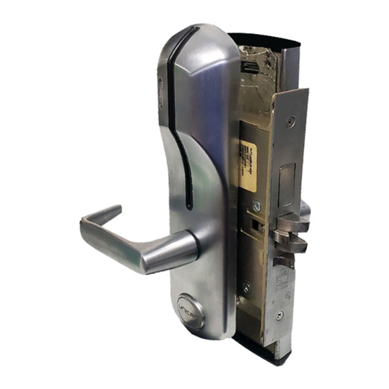
Page 2: Kit Contents
Kit part #062-510479-XXX Warning: Installation of this kit by the end user may cancel the complete lock warranty. Kaba Ilco is not responsible for any damage caused by installation. IMPORTANT: DO NOT install the knob on the insert before instructed to do so. - Page 3 Step by Step Instructions Outside Housing Remove spindle and compression spring. Remove extension spring. Remove retaining ring. 7 1 0 - 1 1 / S M A R T R e t r o f i t I n s t a l l a t i o n I n s t r u c t i o n s • P K 2 9 4 3 P a g e 3...
- Page 4 Step by Step Instructions (cont) Outside Housing Disassemble stop plate (A), bushing (B) and lever. Assemble insert (D) and sleeve (C) from kit with existing nylon bushing (B) and stop plate (A). Check handing 7 1 0 - 1 1 / S M A R T R e t r o f i t I n s t a l l a t i o n I n s t r u c t i o n s • P K 2 9 4 3 P a g e 4...
- Page 5 Step by Step Instructions (cont) Outside Housing Reattach retaining ring in position shown. TIP: Pry up the groove in the insert if necessary. Connect the long extension spring from the knob kit between the stop Closed plate and the hook on the end to housing.
- Page 6 Step by Step Instructions (cont) Outside Housing Assemble the knob on the insert. Ensure it clips in place. TIP: The tooth inside the knob engages the slot on the insert. Insert short half-spindle from kit and compression spring IMPORTANT: See notes at the end of this document before reinstalling lock on door.
- Page 7 Step by Step Instructions (cont) Inside Housing Remove spindle and compression spring. Unscrew two Phillips screws. Remove plate. Remove override cam (A), gear (B) and felt washer (C). Remove extension spring. Remove retaining ring. 7 1 0 - 1 1 / S M A R T R e t r o f i t I n s t a l l a t i o n I n s t r u c t i o n s • P K 2 9 4 3 P a g e 7...
- Page 8 Step by Step Instructions (cont) Inside Housing Disassemble stop plate (A), bushing (B) and lever. Assemble insert (D) and sleeve (C) from kit with existing nylon bushing (B) and stop plate (A). Check handing 7 1 0 - 1 1 / S M A R T R e t r o f i t I n s t a l l a t i o n I n s t r u c t i o n s • P K 2 9 4 3 P a g e 8...
- Page 9 Step by Step Instructions (cont) Inside Housing Reattach retaining ring in position shown. TIP: Pry up the groove in the insert if necessary. Connect the short extension spring from the knob kit between the stop plate and the hook on the housing. Closed end to hook...
- Page 10 Step by Step Instructions (cont) Inside Housing If the thumbturn has a pin, position MARK the pin as shown. Install override gear, override cam, and felt washer. POINT MARK MARK POINT 7 1 0 - 1 1 / S M A R T R e t r o f i t I n s t a l l a t i o n I n s t r u c t i o n s • P K 2 9 4 3 P a g e 1 0...
- Page 11 Step by Step Instructions (cont) Inside Housing Reinstall plate DO NOT PINCH BATTERY CABLE ! Assemble the knob TIP: The tooth on the insert. Ensure inside the knob it clips in place. engages the slot on the insert. Insert short half-spindle from kit and compression spring.
-
Page 12: Important Notes
Step by Step Instructions (cont) Inside Housing IMPORTANT NOTES: Always re-install the lock components on the same door from which they were taken. If you disconnected the battery, you will need to reset the lock time to restore the lock to a working condition (see reference manual). - Page 13 Your Total Access Partner Contact our office for the name of the sales representative or dealer/distributor in your region. www.kaba-ilco.com Customer Service: 1-877-468-3555 (North America) Technical Support: 1-800-906-4526 (North America) 1-514-735-5411 (International)
Need help?
Do you have a question about the Solitaire 710-II and is the answer not in the manual?
Questions and answers