Table of Contents
Advertisement
IMPORTANT
• Do not carry out installation, setup, service, or
maintenance until thoroughly understanding the
contents of this manual.
• Keep this manual available at all times for
installation, setup, service, and maintenance.
INS-100 Service Manual No. 085-6692-09
BATTERY DRIVEN SCALE
INS-100
Service Manual
Second Edition
Advertisement
Table of Contents

Subscribe to Our Youtube Channel
Related Manuals for ISHIDA INS-100


Summary of Contents for ISHIDA INS-100
- Page 1 Second Edition IMPORTANT • Do not carry out installation, setup, service, or maintenance until thoroughly understanding the contents of this manual. • Keep this manual available at all times for installation, setup, service, and maintenance. INS-100 Service Manual No. 085-6692-09...
- Page 2 Ishida. No patent liability is assumed with respect to the use of the information contained herein. Moreover, because Ishida is constantly striving to improve its high-quality products, the information contained in this manual is subject to change without notice.
- Page 3 ISHIDA assumes no responsibility for clerical, typographical or proofreading errors, or omissions. LIMITATIONS OF LIABILITY ISHIDA is not liable for any damage, loss or injury that results from incorrect handling, insufficient caution, unauthorized modifications to the machine, or failure to follow the instructions contained in this manual.
- Page 4 Indicates information that, if not heeded, could possibly result in loss of life or serious injury. Indicates information that, if not heeded, could result in relatively serious or minor injury, damage to the machine, or faulty operation. INS-100 Service Manual No. 085-6692-09...
- Page 5 AC Power Supply (when used) • Use the specified voltage after referring to the specification plate located on the machine. • Use a dedicated power source. (Voltage fluctuation may cause the machine to malfunction) INS-100 Service Manual No. 085-6692-09...
- Page 6 • Always ensure that the machine is level. If the machine is not level, weighing may not be accurate. • Adjust the machine to a level position using the four level adjustment feet located on the button of the machine, until the bubble is completely centered in the round level indicator. INS-100 Service Manual No. 085-6692-09...
-
Page 7: Table Of Contents
Replacing the Transformer ................30 Replacing the Battery ..................31 4. REFERENCE DATA ..................... 32 E2ROM Map (0 - 127) Data Format..............32 Weighing Condition Setting Table (D008A)............33 Weighing Capacity Number Table..............35 Country Code Table (D008A)................36 INS-100 Service Manual No. 085-6692-09... - Page 8 5. DIAGRAMS ......................37 External Dimensions..................37 Exploded Diagram ................... 38 Parts List......................40 Block Diagram ....................41 Main Board Circuit Diagram................42 Display Board Circuit Diagram................. 43 Key Board Circuit Diagram ................43 6. TROUBLESHOOTING..................44 INS-100 Service Manual No. 085-6692-09...
-
Page 9: Product Overview
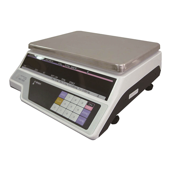
Chapter 1 PRODUCT OVERVIEW 1. PRODUCT OVERVIEW Front View Weigh platter Operator display Upper case Lower case Operating panel Height adjustment foot Level Keys INS-100 Service Manual No. 085-6692-09... -
Page 10: Rear View
Chapter 1 PRODUCT OVERVIEW Rear View Customer display Operating Panel Level guide INS-100 Service Manual No. 085-6692-09... -
Page 11: Basic Specifications
(Can be driven by the rechargeable lead storage battery: option) Main functions 1/4 and 1/2 price key function Auto power OFF function “lb” / “kg” change function Weight only display function Total function Option None INS-100 Service Manual No. 085-6692-09... -
Page 12: Setup Procedure
Auto power function check Auto power function can be checked. Country setting check Country setting and weighing conditions can be checked. Power OFF ON/OFF key Various Modes Start Normal Mode Checking Scale ON TARE Voltage Check Mode Setup Mode Test Mode INS-100 Service Manual No. 085-6692-09... -
Page 13: Items In Each Mode
Scale adjustment (country code, weighing capacity, area, zero, span) Key check Display check 1 (simplified check) Display check 2 (detailed check) Program number display RAM and E2ROM clear Country specification/Weighing condition settings E2ROM data read INS-100 Service Manual No. 085-6692-09... -
Page 14: Voltage Check Mode
“BATT CHECK” display appears. 6.8V or more 6.6V or more 6.4V or more Voltage level 6.2V or more 6.0V or more 6.0V or less (Charge is required) Note: To exit this mode, press the [CLEAR] key. INS-100 Service Manual No. 085-6692-09... -
Page 15: Setup Mode
Set value Menu number. 2.5.2 Key Operation • Used to advance a menu number. ZERO • Used to increase a set value. TARE • Used to decrease a set value. • Used to finish current menu. INS-100 Service Manual No. 085-6692-09... -
Page 16: Menu List
5: 50 minutes F17 Automatic power OFF time setting 6: 60 minutes 7: 0.5 minutes 8: 1 minute 9: 5 minutes Note: To exit this mode, press the [CLEAR] key. F2 – F15 is Invalid function. INS-100 Service Manual No. 085-6692-09... -
Page 17: Test Mode
• Used to increase a set value • Used to move menus in descending order like C8 TARE • Used to decrease a set value. • Used to return the display to the first step of current menu. INS-100 Service Manual No. 085-6692-09... -
Page 18: Scale Adjustment (C1 Mode)
• Press the [ZERO] or [TARE] key to increase or decrease the set value. • Press the [ADD] key to move to the zero point adjustment menu (C1-4). • Press the [ZERO] or [TARE] key to increase or decrease the set value. INS-100 Service Manual No. 085-6692-09... - Page 19 • Place weights that are equivalent weight to the weighing capacity on the weigh platter. • Press the [TARE] key to execute span adjustment. • Remove weights from the weigh platter. INS-100 Service Manual No. 085-6692-09...
- Page 20 Chapter 2 INSTALLATION & SETUP • If the memory button is pressed at this point, “STORE OK” display will appear. (Refer to Section 2.6.11 in this Chapter) • Press the [CLEAR] key to return to the C1-5 menu. INS-100 Service Manual No. 085-6692-09...
-
Page 21: Key Check (C2 Menu)
• Press the [ZERO] key twice to enter the simplified display check menu (C3). • Press the [ADD] key to enter the simplified display check menu. All segments will blink. • Press the [CLEAR] key to return to the “C3” menu. INS-100 Service Manual No. 085-6692-09... -
Page 22: Display Check 2 (C4 Menu)
[ZERO] key to enter into “C5” menu. • Press the [ADD] key to advance step. • Confirm on the software number shown on the display. Software number • Press the [CLEAR] key to return to the “C5” menu. INS-100 Service Manual No. 085-6692-09... -
Page 23: Ram/E2Rom Clear (C6 Menu)
• When the Memory Button is pressed, displays will appear as shown in the right. • Press the [CLEAR] key to return to the “C6” menu. Note: Country code will become “0” after RAM data is cleared. INS-100 Service Manual No. 085-6692-09... -
Page 24: Weighing Conditions For Each Country (C7 Menu)
• Press the [ADD] key again to change an address. • Press the [ZERO] or [TARE] key to increase or decrease the set value. Address Set value • Press the [CLEAR] key to return to the “C7” menu. INS-100 Service Manual No. 085-6692-09... -
Page 25: E2Rom Data Read (C8 Menu)
• Press the [ZERO] or [TARE] key to increase or decrease an address. Address Set value Note: This data cannot be changed. • Press the [CLEAR] key to return to the “C8” menu. • Press the [ON/OFF] key to exit Test Mode. INS-100 Service Manual No. 085-6692-09... -
Page 26: Memory Button
• There is a hole for memory button on the base of the machine. • Push the memory button through the hole using a smaller screw-driver or stick to store Memory button all change data in the memory. INS-100 Service Manual No. 085-6692-09... -
Page 27: Component Replacement
3. Detach the display unit. Assembly procedure 1. Place the display unit to its original position. 2. Fix the display unit by tightening the 2 screws. 3. Insert the connector CN1 to the display unit. Screws INS-100 Service Manual No. 085-6692-09... -
Page 28: Customer Display Unit
1. Return the main board to its original position, and fix it with two screws. 2. Insert the connectors CN5, CN4, CN2, and CN1 to their original positions. 3. Solder the 5 load cell harnesses CN6 S, B, G, W, and R. Screw Screw INS-100 Service Manual No. 085-6692-09... -
Page 29: Replacing The Load Cell Unit
2. Fix the load cell with the 2 hex-head nuts on the bottom of the machine. 3. Solder the 5 load cell harnesses CN6 S, B, G, W, and R to the main board. 4. Fix the platter holder to its original position, with the 2 hex-head nuts. INS-100 Service Manual No. 085-6692-09... -
Page 30: Replacing The Transformer
1. Fix the transformer with the 2 screws. 2. Solder the 2 transformer input lead wires. 3. Fix the clamp with the screw. 4. Bind harnesses with the binding clip. 5. Insert the CN2 connector on the main board. INS-100 Service Manual No. 085-6692-09... -
Page 31: Replacing The Battery
Replacing the Battery Disassembly procedure 1. Remove the 2 screws fixing the battery cover. 2. Remove the battery cover. 3. Pull out the battery. 4. Beware of faulty wiring when replacing with a new battery. INS-100 Service Manual No. 085-6692-09... -
Page 32: Reference Data
0 - 15 Note: Refer to the district code table. Adjusted span flag 125B 5H or others 5H = OK Others = Error 126, 127 No.100 - 113 checksum Note: F2 – F15 is Invalid function. INS-100 Service Manual No. 085-6692-09... -
Page 33: Weighing Condition Setting Table (D008A)
1: 100g (0.1lb) Price fraction processing 0: Half-adjust 1: Round-down Price display in instability 0: Display 1: No display Reserve 116B Allow accumulate 0: No 1: Yes Reserve Reserve 0: No 1: Yes Special Price calculation INS-100 Service Manual No. 085-6692-09... - Page 34 15kg 0.005kg 100g unit price 0.002kg 100g unit price 30lb 0.01lb 100g unit price 0.001kg 100g unit price 15lb 0.005lb 100g unit price 6000g 100g unit price 3000g 100g unit price 0.002lb 100g unit price INS-100 Service Manual No. 085-6692-09...
-
Page 35: Weighing Capacity Number Table
(Price/Unit price 4 digits) 3kg (0.001kg) 1/3000 single range (Price/Unit price 4 digits) Setting of individual weighing capacity * Individual setting value “99” cannot be entered. (Displayed only when setting is changed in the C7 mode) INS-100 Service Manual No. 085-6692-09... -
Page 36: Country Code Table (D008A)
Manual tare entry function Zero tracking function Slight weight follow processing 8 Unstable width Price decimal point position 4 price calculation 1 Unit price Price fraction processing Price display in instability 1 Allow accumulate Special Price calculation INS-100 Service Manual No. 085-6692-09... -
Page 37: Diagrams
Chapter 5 DIAGRAMS 5. DIAGRAMS External Dimensions φ (Unit: mm) INS-100 Service Manual No. 085-6692-09... -
Page 38: Exploded Diagram
Chapter 5 DIAGRAMS Exploded Diagram Drawing No. 900-3251-02-0 (South Africa Specification) INS-100 Service Manual No. 085-6692-09... - Page 39 Battery Cover 900-3258-** Power Cord 900-0227-** Seal Screw M4 900-2576-** Screw Washer 900-1331-** Storage Battery 900-2820-** Connector Inlet 900-0223-** Level unit 900-2812-** PWB 'PS-031' Soft (D007) *South Africa 15Kg Specification as of April, 2006 INS-100 Service Manual No. 085-6692-09...
-
Page 40: Parts List
Harness 'S2' Key 900-2495-01 Harness 'S2' GND 900-2598-01 Harness 'S1' GND 900-2525-09 Harness 'C3' Battery 900-2483-06 Harness 'S3' Display 900-2819-03 Transformer 'LYTR-011201M-1' INS-100 220V 900-2820-08 Connector Inlet (PST-101FS PRONIC) 900-0042-00 Fuse Glass 5 X 20mm 1A INS-100 Service Manual No. 085-6692-09... -
Page 41: Block Diagram
Chapter 5 DIAGRAMS Block Diagram KK-3P XH-2P Terminal Terminal INS-100 Service Manual No. 085-6692-09... -
Page 42: Main Board Circuit Diagram
Chapter 5 DIAGRAMS Main Board Circuit Diagram INS-100 Service Manual No. 085-6692-09... -
Page 43: Display Board Circuit Diagram
Chapter 5 DIAGRAMS Display Board Circuit Diagram Key Board Circuit Diagram INS-100 Service Manual No. 085-6692-09... -
Page 44: Troubleshooting
• The battery cannot be when the power supply is function is operating to protect turned on. the battery over electrical charged because of discharge. Due to voltage deterioration. decrease. (About 5.4V or less while energized) INS-100 Service Manual No. 085-6692-09... - Page 45 Design and specifications are subject to change without notice. 44 SANNO-CHO, SHOGOIN, SAKYO-KU KYOTO, 606-8392 JAPAN PHONE: 81-75-771-4141 FACSIMILE: 81-75-751-1634 URL: http://www.ishidajapan.com...
Need help?
Do you have a question about the INS-100 and is the answer not in the manual?
Questions and answers