Advertisement
Advertisement
Table of Contents

Summary of Contents for Worx WG118E
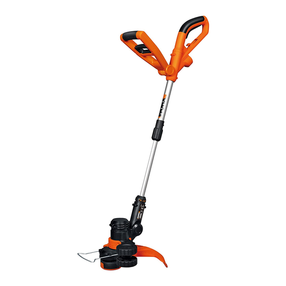
- Page 1 SAFETY AND OPERATING MANUAL 2-in-1 Grass Trimmer/Edger WG1 18E...
-
Page 2: General Safety Warnings
GENERAL SAFETY BEFORE DISCONNECTING THE SUPPLY. Do not use the appliance if the cord is WARNINGS damaged or worn. 2. Read the instructions carefully. Be familiar WARNING!When using the machine with the controls and proper use of the the safety rules must be followed. equipment. - Page 3 SYMBOLS 22. Take care against injury from any device fitted for trimming the filament line length. After extending new cutter line always return the machine to its normal operating position before switching on; Read instruction sheet 23. Never fit metal cutting elements; 24.
- Page 4 2-in-1 Grass Trimmer/Edger WG1 18E...
-
Page 5: Auxiliary Handle
REAR HANdlE PlUG INSERT lOCkING COllAR SAfETy GUARd SPACER GUARd TElESCOPIC SHAfT AUxIlIARy HANdlE EdGER WHEEl lINE CUTTER 10. AUxIlIARy HANdlE lOCkING lEVER 11. CUTTING HEAd COVER (See fig. k ) 12. CAP RElEASE lATCH (See fig. k) 13. SPOOl (See fig. k) 14. -
Page 6: Technical Data
TECHNICAL DATA Rated voltage 220–240V~50/60Hz Power 550W No load speed 8900/min Cutting diameter 30cm Line diameter 1.65mm Line length 2*5m machine weight 2.8kg ACCESSORY Safety guard Auxiliary handle Edger wheel Spacer guard We recommend that you purchase your accessories from the same store that sold you the tool. Use good quality accessories marked with a well-known brand name. -
Page 7: Operating Instructions
ASSEMBLY 1. ASSEMBly Of THE SAfETy GUARd (See fig. A) Remove the screw from the Safety Guard (4) and fit the guard to the trimmer head; align the guard so it slides into the slots located on the trimmer head. Turn the tool over and secure the Safety Guard onto the trimmer head with the screw (a) provided. - Page 8 2. AdJUSTMENT Of THE TElESCOPIC SHAfT (See fig. d) Unscrew the Locking Collar (3) clockwise to unlock, as indicated. Adjust the length of the Telescopic Shaft (6)to the most comfortable length. Tighten the Locking Collar counter-clockwise to lock, as indicated. 3.
- Page 9 5. ATTACHING ExTENSION CORd(See fig. G) An extension cord retainer is built into the Rear Handle (1) that prevents the cord from coming unplugged. To use this feature, simply double the extension cord about (203mm from the end, forming a small loop.
- Page 10 A ‘clattering’ noise will be heard for a short time. This is normal and is caused by the line being cut by the line cutter. Once the line is cut to the correct length, the ‘clattering’ noise will stop and the trimmer motor will run at full speed.
-
Page 11: Maintenance
separate piece of line on lower section of Spool (See Fig. L2 & L3). Leave approximately 100mm of line unwound and place it into the cleat. Repeat on the lower section of the Spool. Care should be taken to ensure that the line is neatly coiled on the Spool (See Fig L4). - Page 12 Copyright © 2013, Positec. All Rights Reserved. 2GGT12CPK11002A0...


Need help?
Do you have a question about the WG118E and is the answer not in the manual?
Questions and answers