Epson TM-T70II Technical Reference Manual
Receipt printer
Hide thumbs
Also See for TM-T70II:
- Technical reference manual (102 pages) ,
- User manual (11 pages) ,
- Product information manual (4 pages)
Table of Contents
Advertisement
Quick Links
Technical Reference Guide
Product Overview
Describes features and general specifications for the product.
Setup
Describes setup and instrallation of the product and peripherals.
Application Development Information
Describes how to control the printer and necessary information
when you develop applications.
Handling
Describes how to handle the product.
Replacement of the TM-T70
Describes precautions for replacement.
Appendix
Describes interfaces, connectors and character code tables.
M00063501
Rev. B
Advertisement
Table of Contents

Related Manuals for Epson TM-T70II


Summary of Contents for Epson TM-T70II
- Page 1 Technical Reference Guide Product Overview Describes features and general specifications for the product. Setup Describes setup and instrallation of the product and peripherals. Application Development Information Describes how to control the printer and necessary information when you develop applications. Handling Describes how to handle the product.
- Page 2 • Neither is any liability assumed for damages resulting from the use of the information contained herein. • Neither Seiko Epson Corporation nor its affiliates shall be liable to the purchaser of this product or third parties for damages, losses, costs, or expenses incurred by the purchaser or third parties as a result of: accident, misuse, or abuse of this product or unauthorized modifications, repairs, or alterations to this product, or (excluding the U.S.) failure to strictly comply with Seiko Epson Corporation’s operating...
-
Page 3: For Safety
For Safety Key to Symbols The symbols in this manual are identified by their level of importance, as defined below. Read the following carefully before handling the product. You must follow warnings carefully to avoid serious bodily injury. WARNING Provides information that must be observed to prevent damage to the equipment or loss of data. -
Page 4: Warnings
Shut down your equipment immediately if it produces smoke, a strange odor, or unusual noise. Continued use may lead to fire. Immediately unplug the equipment and contact your dealer or a Seiko Epson service center for advice. Never attempt to repair this product yourself. Improper repair work can be dangerous. -
Page 5: Cautions
Cautions Do not connect cables in ways other than those mentioned in this manual. Different connections may cause equipment damage or fire. Be sure to set this equipment on a firm, stable, horizontal surface. CAUTION The product may break or cause injury if it falls. ... -
Page 6: About This Manual
About this Manual Aim of the Manual This manual was created to provide information on development, design, and installation of POS systems and development and design of printer applications for developers. Manual Content The manual is made up of the following sections: Chapter 1 Product Overview Chapter 2... -
Page 7: Table Of Contents
Contents ■ For Safety..........................3 Key to Symbols ............................3 Warnings ..............................4 Cautions..............................5 ■ Restriction of Use ........................5 ■ About this Manual ........................6 Aim of the Manual..........................6 Manual Content ............................ 6 Product Overview ................13 ■ Features ..........................13 ■ Product Configuration ......................15 Interface ............................... - Page 8 Electrical Characteristics........................36 Environmental Conditions ........................37 External Dimensions and Mass......................38 ■ Option Specifications ......................39 AC Adapter (PS-180)..........................39 Setup .....................41 ■ Flow of Setup........................41 ■ Installing the Printer......................42 Important Notes on Installation ......................43 Affixing Position of DF-10 ........................43 ■ Connecting the Printer to the Host Computer ..............44 For Serial Interface..........................44 For Parallel Interface ..........................47 For USB Interface...........................48...
- Page 9 ■ Setting/Checking Modes....................82 Self-test Mode ............................82 Hexadecimal Dumping Mode ......................84 NV Graphics Information Print Mode ....................85 R/E (Receipt Enhancement) Information Print Mode ..............86 Memory Switch Setting Mode......................87 Handling ..................93 ■ Installing and Replacing Roll Paper..................93 ■...
- Page 10 Appendix ..................105 ■ Specifications of Interface and Connector ..............105 RS-232 Serial Interface........................105 IEEE 1284 Parallel Interface........................108 USB (Universal Serial Bus) Interface ....................111 ■ Character Code Tables ....................112 Common to All Pages........................112 Page 0 [PC437: USA, Standard Europe]...................113 Page 1 (Katakana)..........................114 Page 2 (PC850: Multilingual) ......................115 Page 3 (PC860: Portuguese) ......................116 Page 4 (PC863: Canadian-French)....................117...
- Page 11 Page 255 (User-Defined Page) ......................155 International Character Sets ......................156...
-
Page 13: Product Overview
This chapter describes features and specifications of the product. Features The TM-T70II is a receipt printer with high speed printing and a small footprint. With its compact design, it can be placed in a narrow space, such as under a counter, and it also has full front access for easy operability. - Page 14 Others • Various interface boards (EPSON UB series) can be used. • The TM-T70II Software & Documents Disc (drivers, utility software, and manuals)
-
Page 15: Product Configuration
• Model without the buzzer function The optional external buzzer and the internal buzzer cannot be used together at the same time. Color • ECW (Epson Cool White) • EDG (Epson Dark Gray) Accessories Included • Roll paper (for operation check) •... - Page 16 • Locking wire saddle* • The TM-T70II Software & Documents Disc (drivers, utility software, and manuals)* • Setup Guide • Warranty certificate* * May not be included depending on the model. Options • AC adapter • AC cable • Connector cover (Model: OT-CC702W/OT-CC702B)...
-
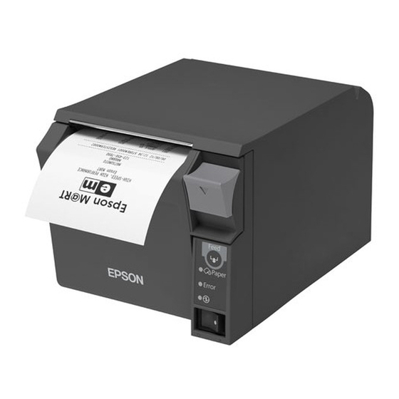
Page 17: Parts Name And Function
Chapter 1 Product Overview Parts Name and Function Manual cutter Roll paper cover Cover open lever Control panel Power switch cover Power switch Power Switch Turns the printer on or off. The marks on the switch: ( Before turning on the printer, be sure to check that the AC adapter is connected to the power supply. -
Page 18: Power Switch Cover
Power Switch Cover Install the power switch cover that comes with the TM-T70II onto the printer to prevent inadvertent changing of the power switch, to prevent tampering, and to improve the appearance of the printer. To reset the printer when the power switch cover is installed, insert a long, thin object (such as the end of a paper clip) into the hole in the power switch cover and press the power switch. -
Page 19: Connectors
Chapter 1 Product Overview • Lights when the end of the roll paper is detected, and when printing has stopped (offline). If this happens, replace the roll paper. • Flashes when an error occurs. (For details about the flash codes, see "Error Status"... - Page 20 • When the roll paper cover is open • While roll paper is fed using the Feed button • When the printer stops printing due to a paper-end (if an empty paper supply is detected by the roll paper end sensor or if the driver has been set to stop printing when a roll paper near- end is detected) •...
-
Page 21: Error Status
Chapter 1 Product Overview Error Status There are three possible error types: automatically recoverable errors, recoverable errors, and unrecoverable errors. Automatically Recoverable Errors Printing is no longer possible when automatically recoverable errors occur. They can be recovered easily, as described below. Error LED flash code Error Error description... -
Page 22: Unrecoverable Errors
Unrecoverable Errors Printing is no longer possible when unrecoverable errors occur. The printer must be repaired. Turn off the power immediately when unrecoverable errors occur. CAUTION Error LED flash code Error Error description Approx. 160 ms Memory R/W error After R/W checking, the printer does not work correctly. -
Page 23: Nv Memory (Non-Volatile Memory)
Graphics, such as shop logos to be printed on receipts, can be stored. Even with a serial interface model whose communication speed is low, high speed graphics printing is possible. Use the TM-T70II Utility to register graphics. You can also use the TM-T70II Utility or the NV graphics information print mode to confirm the registered graphics. -
Page 24: Memory Switches
NV memory. You can read the information with the Status API of the APD or OPOS ADK to use it for periodical checks or part replacement. Maintenance Counter can be checked with the TM-T70II Utility or in a self-test. -
Page 25: Product Specifications
Chapter 1 Product Overview Product Specifications Printing method Thermal line printing Cutting method Partial cut (cutting with one point in left edge left uncut) Roll paper (single-ply) width 80 mm width paper printing: 79.5 ± 0.5 mm {3.13 ± 0.02"} 58 mm width paper printing: 57.5 ±... -
Page 26: Printing Specifications
Weight (mass) Approx. 1.7 kg {3.75 lb} (Roll paper excluded) Printing Specifications 80 mm width paper 58 mm width paper printing printing Printing method Thermal line printing Dot density ANK models 180 dpi Simplified Chinese models 203 dpi Traditional Chinese models 203 dpi South Asia font models 203 dpi... - Page 27 Chapter 1 Product Overview Character ANK models 0.28 mm {0.0110"} (2 dots) spacing Simplified Chinese models 0.25 mm {0.0098"} (2 dots) Traditional Chinese models 0.25 mm {0.0098"} (2 dots) South Asia font models 0.25 mm {0.0098"} (2 dots) Maximum print speed* 250 mm/s {9.84"/s} (200 mm/s {7.87"/s} for some models) -: Not supported dpi: dots per inch...
-
Page 28: Character Specifications
Character Specifications Number of characters ANK models Font A (initial setting) Alphanumeric characters: 95 Font B Extended graphics: 128 × 43 pages (including user- defined page) International characters: 18 sets Simplified Font A (initial setting) Alphanumeric characters: 95 Chinese models Font B Extended graphics: 128 ×... -
Page 29: Character Size
Chapter 1 Product Overview Character structure 80 mm width paper 58 mm width paper printing printing Font A (initial setting) 12 × 24 (including 2-dot horizontal spacing) Font B 9 × 17 (including 2-dot horizontal spacing) Kanji font 24 × 24 Special font A 12 ×... - Page 30 Special font A South Asia font 1.25 × 3.00/1.25 × 6.00/2.50 × 3.00/ models 2.50 × 6.00 Special font B South Asia font 0.88 × 3.00/0.88 × 6.00/1.75 × 3.00/ models 1.75 × 6.00 -: Not supported Note: Space between characters is not included. Characters can be scaled up to 64 times as large as the standard size.
-
Page 31: Characters Per Line
Chapter 1 Product Overview Characters per line Standard/Double-height/Double-width/Double-width, double-height W × H (mm) 80 mm width paper 58 mm width paper printing printing Font A ANK models 42/42/21/21 Simplified 48/48/24/24 Chinese models Traditional 48/48/24/24 34/34/17/17 Chinese models South Asia font 48/48/24/24 models Font B... -
Page 32: Printable Area
Printable Area 80 mm paper width printing 79.5 0.5 mm 79.5 0.5 mm 0.141 0.05 mm 0.125 0.05 mm 72.2 0.2 mm 72 0.2 mm (3.65 mm) (3.65 mm) (3.75 mm) (3.75 mm) <203 dpi model> <180 dpi model> <180 dpi model> In 2-divided energizing, the print position within the printable area of the thermal elements for dots 1 to 256 and 257 to 512 is shifted approximately 0.07 mm {0.0028"} as shown in the figure below in the paper feed direction. - Page 33 Chapter 1 Product Overview 58 mm paper width printing 57.5 0.5 mm 0.125 0.05 mm 0.2 mm (2.75 mm) (2.75 mm) In 2-divided energizing, the print position within the printable area of the thermal elements for dots 1 to 208 and 209 to 416 is shifted approximately 0.06 mm {0.0024"} as shown in the figure below in the paper feed direction.
-
Page 34: Printing And Cutting Positions
Printing and Cutting Positions Manual-cutter position Approx. 30 Approx. 13 Autocutter blade position Center of the print dotline Paper feed direction [units: mm (All the numeric values are typical.)] The values above may vary slightly as a result of paper slack or variations in the paper. Take the notice into account when setting the cutting position of the autocutter. - Page 35 Chapter 1 Product Overview Specified original paper type TF50KS-E, TF60KS-E (NIPPON Paper Industries Co., Ltd.) PD160R, PD190R (OJI Paper Mfg. Co., Ltd.) P220AGB-1 (Mitsubishi Paper Mills Limited.) P300, P310, P350 (Kanzaki Specialty Papers) AF50KS-E (Jujo Thermal Oy) F5041 (Mitsubishi HiTec) KT55F20, KT48F20 (Koehler Paper Group) ...
-
Page 36: Electrical Characteristics
Electrical Characteristics Supply voltage DC 24 V ± 7% Current consumption Standby Mean: Approximately 0.1 A (at 24 V, 25°C, normal Maximum 1 A for drawer kick-out driving. print density) Operating Mean: Approximately 2.0 A (180 dpi model) (80 mm Mean: Approximately 1.5 A (203 dpi model) width Note: When print ratio is... -
Page 37: Environmental Conditions
Ambient temperature Acoustic noise (Operating) Approximately 55 dB (Bystander position) Note: The values above are measured in the Epson evaluation condition. The acoustic noise differs depending on the paper used, printing contents, or the setting values such as print speed or... -
Page 38: External Dimensions And Mass
External Dimensions and Mass • Height: Approximately 114 mm {4.49"} • Width: Approximately 125 mm {4.92"} • Depth: Approximately 194 mm {7.64"} • Mass: Approximately 1.7 kg {3.75 lb} (except for roll paper) <When the Optional OT-CC702W/OT-CC702B is installed> 255.5 [Units: mm]... -
Page 39: Option Specifications
Chapter 1 Product Overview Option Specifications AC Adapter (PS-180) [Units: mm] Electric Input conditions input voltage (rating): AC 90 to 264 V characteristics (AC 100 V -10% to AC 230 V +15%) Frequency (rating): 50/60 Hz ± 3 Hz Power consumption (rating): 100 VA Output conditions Output voltage (rating): DC 24 V ±... -
Page 41: Setup
Chapter 2 Setup Setup This chapter describes setup and installation of the product and peripherals. Flow of Setup This chapter consists of the following sections along with the setup flow of the product and peripherals. Installing the Printer (page 42) Connecting the Printer to the Host Computer (page 44) Connecting the AC Adapter (PS-180) (page 53) Setting the Memory Switches/Receipt Enhancement (page 54) -
Page 42: Installing The Printer
Installing the Printer You can install this printer only horizontally. Fix the printer so that it does not move around when you open the roll paper cover and cut roll paper. A tape for fixing the printer is available as an option. (See "Affixing Position of DF-10"... -
Page 43: Important Notes On Installation
Chapter 2 Setup Important Notes on Installation • The printer must be installed horizontally. • Do not place the printer in dusty locations. • Do not catch cables or foreign matter under the printer. • Do not put anything that has a force of more than 32.7 N {3 kgf} on the top of the printer. Affixing Position of DF-10 When you use the affixing tapes for fixing the printer (Model: DF-10), paste them as shown in the figure below. -
Page 44: Connecting The Printer To The Host Computer
(DM-D) is to be connected, connect it to the host computer via the serial port or USB port. AC adapter + AC cable DM-D (Serial I/F model) Extension cable for power supply Serial cable Cash drawer TM-T70II Modular cable Serial cable DM-D (USB I/F model) AC adapter + AC cable USB cable Cash drawer... - Page 45 Baud rate: 19200 bps Bit length: 8-bit Parity: no parity Stop bit: 1 Modular cable DM-D TM-T70II Modular cable Serial cable Cash drawer AC adapter + AC cable Connecting the serial interface (RS-232) cable Be sure to turn off the power supply for both the printer and host computer before connecting the cables.
- Page 46 When using interface cables equipped with a grounding line, attach the ground line to the screw hole marked “FG” on the printer. Connect the other end of the interface cable to the host computer.
-
Page 47: For Parallel Interface
Use the extension cable for power supply bundled with the customer display. AC adapter + AC cable DM-D (Serial I/F model) Extension cable for power supply Serial cable Cash drawer TM-T70II Parallel cable Modular cable DM-D (USB I/F model) AC adapter + AC cable USB cable Cash drawer... -
Page 48: For Usb Interface
(DM-D) is to be connected, connect it to the host computer via the serial port or USB port. AC adapter + AC cable DM-D (Serial I/F model) Extension cable for power supply Serial cable TM-T70II Cash drawer Modular cable USB cable DM-D (USB I/F model) AC adapter + AC cable... -
Page 49: Connecting The Usb Interface Cable
Baud rate: 19200 bps Bit length: 8-bit Parity: no parity Stop bit: 1 Modular cable DM-D TM-T70II Modular cable USB cable Cash drawer AC adapter + AC cable Connecting the USB interface cable Attach the locking wire saddle at the location shown in the figure below. -
Page 50: For Lan Interface
For LAN Interface Connect the printer to a network by a LAN cable via a hub. For the setting method of the IP address, see the TM-T70II Software User’s Manual. LAN interface connection diagram DM-D 10BASE-T/100BASE-TX M o d u l a r... - Page 51 Chapter 2 Setup Connect a 10BASE-T/100BASE-TX cable to the 10BASE-T/100BASE-TX LAN connector by pressing firmly until the connector clicks into place. 10BASE-T/100BASE-TX LAN NOT FOR TELECOMMUNICATION USE interface connector KEIN TELEFONANSCHLUSS M6 Switch L E D (Green) (Yellow) Press down the switch for a while when the power is on to initialize to the factory settings.
-
Page 52: For Wireless Lan Interface
For Wireless LAN Interface For details on how to set up a wireless LAN interface, see the TM-T70II Software User’s Manual. Wireless LAN interface connection diagram Access point Modular cable Cash drawer TM-T70II... -
Page 53: Connecting The Ac Adapter (Ps-180)
Connecting the AC Adapter (PS-180) Use the PS-180 or an equivalent product as the AC adapter. Always use the EPSON PS-180 or an equivalent product as the AC adapter. Using a nonstandard power supply can result in electric shock and fire. -
Page 54: Setting The Memory Switches/Receipt Enhancement
For an outline of the functions, see the following section. Use the methods shown in the table below; TM-T70II Utility, Memory Switch Setting Mode, or ESC/POS commands, to set the memory switches and R/E functions. -
Page 55: Functions
*2: Enabled only for South Asia font models *3: Enabled only for ANK models *4: Excluding some functions. For information about the TM-T70II Utility, see the TM-T70II Utility User’s Manual. For information about how to use the memory switch setting mode, see "Memory Switch Setting Mode"... -
Page 56: Auto Line Feed
Processing when data receive error • Prints “?” (initial setting) • Ignored Auto line feed • Always disabled (initial setting) • Always enabled USB power-saving function • Disabled • Enabled (initial setting) The USB power-saving function is valid only when the USB interface communication condition is set to the vendor-defined class and the system configuration is set so that the USB driver can support the USB power-saving function. - Page 57 Chapter 2 Setup Depending on the paper type, it is recommended to set the print density as shown in the table below for the best print quality. Original Paper type Density Level TF50KS-E, P220AGB-1, AF50KS-E Level 5 (90%) TF60KS-E, PD160R, PD190R, KT48F20, KT55F20, Level 7 (100%) F5041 P300, P310, P350...
-
Page 58: Interface Selection
Usually, the number of head energizing parts does not need to be changed. When printing at the maximum speed, select “One-part energizing.” Character code table default Selectable from 43 pages including user defined page Initial setting: Page 0 (PC437: USA, Standard Europe) ... - Page 59 Chapter 2 Setup Autocutting after closing cover • Cuts • Does not cut (initial setting) Paper reduction Extra upper space reduction • Disabled (initial setting) • Enabled Extra lower space reduction • Disabled (initial setting) • Enabled Line space reduction rate •...
- Page 60 Font A auto replacement • Does not replace (initial setting) • Font B Font B auto replacement • Does not replace (initial setting) • Font A Buzzer For models without the internal buzzer function, the optional external buzzer (OT-BZ20) needs to be connected to use the buzzer function.
- Page 61 Chapter 2 Setup Buzzer frequency (Pulse 1) • Does not sound (initial setting) • Sounds 1 time Sound pattern (Pulse 2) (only for the optional external buzzer) Selectable from Patterns A to E Initial setting: Pattern B Buzzer frequency (Pulse 2) •...
- Page 62 Communication condition of USB interface • USB printer class • USB vendor-defined class (initial setting) Auto top logo TM-T70II Utility does not support the function for Number of lines to be deleted below top logo. Key-code Selectable from key-codes of registered logos Alignment •...
- Page 63 Chapter 2 Setup Auto top/bottom logo extended functions TM-T70II Utility does not support the following functions. Top logo print while paper feeding to the cutting position Top logo print while clearing the buffer to recover from a recoverable error ...
-
Page 64: Connecting The Optional External Buzzer
Connecting the Optional External Buzzer When using the optional external buzzer (OT-BZ20), install the optional external buzzer. If your printer is not equipped with a buzzer, you can use the optional external buzzer (OT- BZ20) by connecting it to the drawer. ... -
Page 65: Installation Position
Chapter 2 Setup Installation Position This product is recommended to be installed in the following position. • Either side of the printer. Do not install the optional external buzzer at the roll paper exit. To prevent liquid from entering inside, it is recommended to install the optional external buzzer so that the volume adjustment knob is positioned sideways or downward. -
Page 66: Installation Procedures
Installation Procedures Turn off the printer. Connect and disconnect the optional external buzzer while the printer is turned off. If you connect it while the printer is turned on, the buzzer does not function correctly. Clean and dry the printer case where the optional external buzzer will be installed. -
Page 67: Adjusting The Buzzer Volume
Chapter 2 Setup Peel off the sticker on the other side of the affixing tape, and attach and fix the optional external buzzer to the printer case. Printer case Turn on the printer. Make settings for the optional external buzzer on the printer. ... -
Page 68: Connecting The Cash Drawer
Connecting the Cash Drawer Use the cash drawer handled by EPSON or your dealer. Connecting the Drawer Kick-out Cable Specifications of drawers differ depending on makers or models. When you use a drawer other than specified, make sure its specification meets the following con- ditions.... -
Page 69: Setting The Internal Buzzer (For Models With An Internal Buzzer)
Chapter 2 Setup Drawer connection diagram Drawer kick-out connector With shielded Drawer kick-out solenoid Control device Drawer open/close switch User side [Drawer kick-out side] Printer side Setting the Internal Buzzer (for Models with an Internal Buzzer) Models with the buzzer function can beep the buzzer when the drawer is opened, by setting the properties of the driver or outputting a pulse signal by a command. -
Page 71: Application Development Information
Chapter 3 Application Development Information Application Development Information This chapter describes how to control the printer and gives information useful for printer application development. How to Control the Printer Use a driver or ESC/POS commands to control the printer. Selecting a Driver Choose one of the drivers listed in "Software and Manuals"... -
Page 72: Esc/Pos Command
ESC/POS Command ESC/POS is the Epson original printer command system. With ESC/POS commands, you can directly control all the TM printer functions, but detailed knowledge of printer specifications or combination of commands is required compared to using a driver. The ESC/POS command functions are listed as follows. For detailed information about ESC/ POS commands, see the ESC/POS Command Reference. - Page 73 Chapter 3 Application Development Information Define user-defined characters Cancel user-defined characters Cancel print data in page mode Commands for panel buttons Enable/disable panel buttons Commands for paper sensors Select paper sensor(s) to stop printing Select paper sensor(s) to output paper-end signals Commands for print positions Horizontal tab Set horizontal tab positions...
- Page 74 Transmit the key code list for defined download graphics Delete all download graphics data Delete the specified download graphics data Define the downloaded graphics data (raster format) Print the specified download graphics data Store the graphics data in the print buffer (raster format) Select bit-image mode Define downloaded bit image Print downloaded bit image...
- Page 75 Chapter 3 Application Development Information PDF417: Transmit the size information of the symbol data in the symbol storage area QR Code: Select the model QR Code: Set the size of module QR Code: Select the error correction level QR Code: Store the data in the symbol storage area QR Code: Print the symbol data in the symbol storage data area QR Code: Transmit the size information of the symbol data in the symbol storage area MaxiCode: Select the mode...
- Page 76 Transmit the setting of the memory switch Set the customized setting values Transmit the customized setting values Set the configuration item for the serial interface Transmit the configuration item for the serial interface Set conditions for USB interface communication Transmit conditions for USB interface communication Delete the specified record of NV user memory Store the data in the specified record of NV user memory Transmit the data in the specified record of NV user memory...
- Page 77 Chapter 3 Application Development Information Select the print speed Select the number of parts for the thermal head energizing Initialize maintenance counter Transmit maintenance counter Commands for receipt enhancement Cancel set values for top/bottom logo printing Transmit set values for top/bottom logo printing Set top logo printing Set bottom logo printing Make extended settings for top/bottom logo printing...
-
Page 78: Software And Manuals
POS, such as controls for paper cut, a cash drawer, or customer display. The Devmode API/PRINTERINFO Manual Status API (Epson original DLL) that monitors printer Status API Manual status and sends ESC/POS commands is also ... - Page 79 Windows drivers. It is not a driver to be used for printing from commercial applications. *2: This guide describes general information on how to control printers using the OPOS ADK (in the chapter “POS Printer” and “Appendix-A”). It does not describe Epson’s specific functions.
-
Page 80: Utilities
UB-R04 Technical Reference Guide EpsonNet Simple Viewer: EpsonNet Simple Viewer User’s Manual Use for checking the status of EPSON printers connected to a network and EPSON TM/BA printers connected to computers on a network. TM / BA /EU Printer Remote Configuration Tool: TM / BA /EU Printer Remote Configuration Tool User’s Manual... -
Page 81: How To Get Drivers, Manuals, And The Utility
Chapter 3 Application Development Information How to Get Drivers, Manuals, and the Utility Drivers, manuals, and the TM-T70II Utility can be installed by the TM-T70II installer in the included TM-T70II Software & Documents Disc. You can also obtain them from one of the following URLs. -
Page 82: Setting/Checking Modes
Setting/Checking Modes Besides the ordinary print mode, the printer has the following modes to set or check settings of the printer. • Self-test Mode • Hexadecimal Dumping Mode (page • NV Graphics Information Print Mode (page • Receipt Enhancement Information Print Mode (page •... - Page 83 Chapter 3 Application Development Information With the LAN interface, before printing starts, it takes 6 seconds if the IP address is fixed and 13 seconds if the IP address is obtained with the automatic setting. (It may take longer depending on the response time from the host.) When the printer finishes printing the printer status, the following message is printed and the Paper LED flashes.
-
Page 84: Hexadecimal Dumping Mode
Hexadecimal Dumping Mode In the hexadecimal dumping mode, the printer prints the data transmitted from a host computer in hexadecimal numbers and their corresponding characters. Follow the steps below to run this mode. If there is no character corresponding to print data, “.” is printed. ... -
Page 85: Nv Graphics Information Print Mode
Chapter 3 Application Development Information NV Graphics Information Print Mode You can confirm the following information by running the NV graphics information print mode: • Capacity of the NV graphics • Used capacity of the NV graphics • Unused capacity of the NV graphics •... -
Page 86: R/E (Receipt Enhancement) Information Print Mode
R/E (Receipt Enhancement) Information Print Mode You can confirm the following information by running the R/E information mode: • Automatic top logo setting • Automatic bottom logo setting • Extended settings for automatic top/bottom logo Follow the steps below to run this mode. Close the roll paper cover. -
Page 87: Memory Switch Setting Mode
Chapter 3 Application Development Information Memory Switch Setting Mode You can configure the memory switches of the printer. • Receive buffer capacity • BUSY condition • Processing when data receive error • Auto line feed • USB power-saving function • Release condition of receive buffer BUSY •... - Page 88 After the printing has been completed, press the Feed button three times. Then press the Feed button for more than one second. The printer starts printing instructions for settings. Follow the instructions. After one setting has been completed, the printer stores the setting and then starts initializing. After that, the printer returns to the normal mode.
- Page 89 Chapter 3 Application Development Information Setting the memory switch Follow the steps below to run this mode. Enter the memory switch setting mode. 1. Check that the roll paper is set and that the printer is turned off. 2. While pressing the Feed button, turn on the printer. Keep pressing the Feed button until the printer starts printing.
- Page 90 Setting conditions • Print Density Number of times to press the Feed button Settings No change Monochrome Multi-Tone • Serial Interface Settings Number of times to press the Feed button Settings No change Baud Rate Parity Handshaking Data Bits Data Receive Error •...
- Page 91 Chapter 3 Application Development Information • Default Character Number of times to press the Feed button Settings No change Code Page International Character Set • Embedded Font Replacement Number of times to press the Feed button Settings No change Font A Replacement Font B Replacement •...
- Page 92 • Printing Speed Number of times to press the Feed button Settings No change Level 1 (Slow) Level 2 Level 3 Level 4 Level 5 Level 6 Level 7 Level 8 Level 9 Level 10 Level 11 Level 12 Level 13 (Fast) •...
-
Page 93: Handling
Chapter 4 Handling Handling This chapter describes basic handling of the printer. Installing and Replacing Roll Paper Do not open the roll paper cover during printing. The printer may be damaged. Do not touch the manual cutter with your hands when installing or replacing the WARNING roll paper.... - Page 94 Pull out some roll paper, and make sure that the roll paper is set between the paper guides. Paper guides Close the roll paper cover. Tear off the roll paper.
-
Page 95: Removing Jammed Paper
Remove the jammed paper, reinstall the roll, and close the roll paper cover. Cleaning the Thermal Head Epson recommends cleaning the thermal head periodically (generally every 3 months) to maintain receipt print quality. After printing, the thermal head can be very hot. Do not touch it and let it cool before you clean it. -
Page 96: Preparing For Transport
Preparing for Transport Follow the steps below to transport the printer. Turn off the printer. Confirm that LED is off. Remove the power supply connector. Remove the roll paper. Pack the printer upright. -
Page 97: Replacement Of The Tm-T70
TM-T70II prints the same results as the TM-T70 prints. Print Density The print density of the TM-T70II can be set with the memory switch as can the TM-T70. For detailed information about the memory switch, see "Setting the Memory Switches/ Receipt Enhancement"... -
Page 98: Cutting Method
Receive Buffer You can set the receive buffer of the TM-T70II to 4 KB or 45 bytes with the memory switch, while you can set the receive buffer of the TM-T70 with the DIP switch. The buffer full condition and buffer full release condition of the TM-T70II are the same as those of the TM-T70. -
Page 99: Logo Registration
For detailed information about the TM-T70II Utility, see the TM-T70II Utility User’s Manual. Driver Compatibility You can operate the TM-T70II with a driver for the TM-T70 (APD Ver.3xx or later or APD Ver.4.54 or later). You cannot operate the TM-T70 with a driver for the TM-T70II. -
Page 100: Overall Dimensions
For detailed information about ESC/POS commands, see the ESC/POS Command Reference. Overall Dimensions You can place the TM-T70II in the same location as the TM-T70, since its overall dimensions and weight are about the same as or smaller than those of the TM-T70. -
Page 101: Additional Functions And Functional Improvements
Chapter 5 Replacement of the TM-T70 Additional Functions and Functional Improvements Print Speed The TM-T70II has increased its print speed up to a maximum of 250 mm/s (200 mm/s for some models). TM-T70II TM-T70 250 mm/s 170 mm/s Maximum print speed... -
Page 102: Number Of Characters
The TM-T70II allows you to specify tone of images (2 tones/Multi-tone). Interface The USB interface is added to the main unit of the TM-T70II as standard equipment. USB Class When using the built-in USB interface or USB Plus Power, USB printer class can be used beside the USB vendor-defined class. -
Page 103: Memory Switches
For detailed information about the memory switches, see "Setting the Memory Switches/ Receipt Enhancement" on page R/E Information Print Mode The TM-T70II has a Receipt Enhancement (R/E) Information Print mode that lets you confirm the following information: • Automatic top logo setting • Automatic bottom logo setting... -
Page 104: Reliability
Reliability The TM-T70II has improved reliability. TM-T70II TM-T70 Printer mechanism 17 million lines 15 million lines Life Print head 120 million pulses, 120 km 100 million pulses, 100 km Autocutter 1.7 million cuts 1.5 million cuts MCBF 65 million lines... -
Page 105: Appendix
Appendix Appendix Specifications of Interface and Connector For detailed information about LAN or wireless LAN, see one of the following: LAN: UB-E03 Technical Reference Guide Wireless LAN: UB-R04 Technical Reference Guide RS-232 Serial Interface Interface board specifications (RS-232-compliant) Item Specifications Data transfer method... -
Page 106: Functions Of Each Connector Pin
Functions of each connector pin Pin no. Signal name Signal direction Function — Frame ground Output Transmission data Input Reception data Output Equivalent to DTR signal (pin 20) Input This signal indicates whether the host computer can receive data. SPACE indicates that the host computer can receive data. - Page 107 Appendix Memory switch 1-3 Signal Printer status 1 (ON) 0 (OFF) 1) When the printer goes online after turning on the power (or Transmit Transmit reset using the interface) 2) When the receive buffer is released from the buffer full state Transmit Transmit 3) When the printer switches from offline to online...
-
Page 108: Ieee 1284 Parallel Interface
IEEE 1284 Parallel Interface Modes The IEEE 1284 parallel interface supports the following two modes. Mode Communication direction Other information Host Printer communication Compatibility mode Centronics-compliant Printer Host communication Reverse mode Assumes a data transfer from an asynchronous printer Compatibility Mode Compatibility mode allows data transmission from host to printer only: Centronics-compatible. -
Page 109: Interface Signals
Appendix Interface signals Compatibility Source Nibble Mode Byte Mode Mode Host Strobe HostClk HostClk Host/Ptr Data0 (LSB) Data0 (LSB) Data0 (LSB) Host/Ptr Data1 Data1 Data1 Host/Ptr Data2 Data2 Data2 Host/Ptr Data3 Data3 Data3 Host/Ptr Data4 Data4 Data4 Host/Ptr Data5 Data5 Data5 Host/Ptr Data6... - Page 110 Compatibility Source Nibble Mode Byte Mode Mode Host Init Init Init Printer Fault DataAvail/Data0,4 DataAvail Printer DK_STATUS Printer +5 V Host SelectIn 1284-Active 1284-Active NC: Not Connected ND: Not Defined A signal name with a rule above it indicates an “L” active signal. ...
-
Page 111: Usb (Universal Serial Bus) Interface
Appendix USB (Universal Serial Bus) Interface Outline • Full-speed transmission at 12 Mbps [bps: bits per second] • Plug & Play, Hot Insertion & Removable USB transmission specifications USB function Overall specifications According to USB 2.0 specifications Transmission speed USB Full-Speed (12 Mbps) Transmission method USB bulk transmission method Power supply specifications... -
Page 112: Character Code Tables
Character Code Tables The character code tables show only character configurations. They do not show the actual print pattern. “SP” in the table shows a space. Common to All Pages When International character set (See "International Character Sets" on page 156.) is USA:... -
Page 113: Pc437: Usa, Standard Europe]
Appendix Page 0 [PC437: USA, Standard Europe]... -
Page 114: Katakana)
Page 1 (Katakana) -
Page 115: Pc850: Multilingual)
Appendix Page 2 (PC850: Multilingual) -
Page 116: Pc860: Portuguese)
Page 3 (PC860: Portuguese) -
Page 117: Pc863: Canadian-French)
Appendix Page 4 (PC863: Canadian-French) -
Page 118: Pc865: Nordic)
Page 5 (PC865: Nordic) -
Page 119: Pc851: Greek)
Appendix Page 11 (PC851: Greek) -
Page 120: Pc853: Turkish)
Page 12 (PC853: Turkish) -
Page 121: Pc857: Turkish)
Appendix Page 13 (PC857: Turkish) -
Page 122: Pc737: Greek)
Page 14 (PC737: Greek) -
Page 123: Iso8859-7: Greek)
Appendix Page 15 (ISO8859-7: Greek) -
Page 124: Wpc1252)
Page 16 (WPC1252) -
Page 125: Pc866: Cyrillic #2)
Appendix Page 17 (PC866: Cyrillic #2) -
Page 126: Pc852: Latin2)
Page 18 (PC852: Latin2) -
Page 127: Pc858: Euro)
Appendix Page 19 (PC858: Euro) -
Page 128: Ku42: Thai)
Page 20 (KU42: Thai) -
Page 129: Tis11: Thai)
Appendix Page 21 (TIS11: Thai) -
Page 130: Tis18: Thai)
Page 26 (TIS18: Thai) -
Page 131: Tcvn-3: Vietnamese)
Appendix Page 30 (TCVN-3: Vietnamese) -
Page 132: Tcvn-3: Vietnamese)
Page 31 (TCVN-3: Vietnamese) -
Page 133: Pc720: Arabic)
Appendix Page 32 (PC720: Arabic) -
Page 134: Wpc775: Baltic Rim)
Page 33 (WPC775: Baltic Rim) -
Page 135: Pc855: Cyrillic)
Appendix Page 34 (PC855: Cyrillic) -
Page 136: Pc861: Icelandic)
Page 35 (PC861: Icelandic) -
Page 137: Pc862: Hebrew)
Appendix Page 36 (PC862: Hebrew) -
Page 138: Pc864: Arabic)
Page 37 (PC864: Arabic) -
Page 139: Pc869: Greek)
Appendix Page 38 (PC869: Greek) -
Page 140: Iso8859-2: Latin2)
Page 39 (ISO8859-2: Latin2) -
Page 141: Iso8859-15: Latin9)
Appendix Page 40 (ISO8859-15: Latin9) -
Page 142: Pc1098: Farsi)
Page 41 (PC1098: Farsi) -
Page 143: Pc1118: Lithuanian)
Appendix Page 42 (PC1118: Lithuanian) -
Page 144: Pc1119: Lithuanian)
Page 43 (PC1119: Lithuanian) -
Page 145: Pc1125: Ukrainian)
Appendix Page 44 (PC1125: Ukrainian) -
Page 146: Wpc1250: Latin 2)
Page 45 (WPC1250: Latin 2) -
Page 147: Wpc1251: Cyrillic)
Appendix Page 46 (WPC1251: Cyrillic) -
Page 148: Wpc1253: Greek)
Page 47 (WPC1253: Greek) -
Page 149: Wpc1254: Turkish)
Appendix Page 48 (WPC1254: Turkish) -
Page 150: Wpc1255: Hebrew)
Page 49 (WPC1255: Hebrew) -
Page 151: Wpc1256: Arabic)
Appendix Page 50 (WPC1256: Arabic) -
Page 152: Wpc1257: Baltic Rim)
Page 51 (WPC1257: Baltic Rim) -
Page 153: Wpc1258: Vietnamese)
Appendix Page 52 (WPC1258: Vietnamese) -
Page 154: Kz1048: Kazakhstan)
Page 53 (KZ1048: Kazakhstan) - Page 155 Appendix Page 255 (User-Defined Page)
- Page 156 International Character Sets ASCII code (Hex) Country France à ° ç § é ù è ¨ Germany § Ä Ö Ü ä ö ü β U.K. £ Denmark I Æ Ø Å æ ø å Sweden ¤ É Ä Ö Å...
Need help?
Do you have a question about the TM-T70II and is the answer not in the manual?
Questions and answers