Table of Contents
Advertisement
Technical Reference Guide
Product Overview
Describes features and general specifications for the product.
Setup
Describes setup and instrallation of the product and peripherals.
Application Development Information
Describes how to control the printer and necessary information
when you develop applications.
Handling
Describes how to handle the product.
Appendix
Describes interfaces, connectors and character code tables.
410620803
Rev. C
Advertisement
Table of Contents

Related Manuals for Epson TM T70


Summary of Contents for Epson TM T70
- Page 1 Describes features and general specifications for the product. Setup Describes setup and instrallation of the product and peripherals. Application Development Information Describes how to control the printer and necessary information when you develop applications. Handling Describes how to handle the product.
-
Page 2: Command System
• Neither is any liability assumed for damages resulting from the use of the information contained herein. • Neither Seiko Epson Corporation nor its affiliates shall be liable to the purchaser of this product or third parties for damages, losses, costs, or expenses incurred by the purchaser or third parties as a result of: accident, misuse, or abuse of this product or unauthorized modifications, repairs, or alterations to this product, or (excluding the U.S.) failure to strictly comply with Seiko Epson Corporation’s operating... -
Page 3: For Safety
For Safety Key to Symbols The symbols in this manual are identified by their level of importance, as defined below. Read the following carefully before handling the product. You must follow warnings carefully to avoid serious bodily injury. WARNING Provides information that must be observed to prevent damage to the equipment or loss of data. -
Page 4: Warnings
• Shut down your equipment immediately if it produces smoke, a strange odor, or unusual noise. Continued use may lead to fire. Immediately unplug the equipment and contact your dealer or a Seiko Epson service center for advice. • Never attempt to repair this product yourself. Improper repair work can be dangerous. -
Page 5: Cautions
Cautions • Do not connect cables in ways other than those mentioned in this manual. Different connections may cause equipment damage or fire. • Be sure to set this equipment on a firm, stable, horizontal surface. CAUTION The product may break or cause injury if it falls. •... -
Page 6: About This Manual
About this Manual Aim of the Manual This manual was created to provide information on development, design, and installation of POS systems and development and design of printer applications for developers. Manual Content The manual is made up of the following sections:... -
Page 7: Table Of Contents
Contents ■ Revision History ...2 ■ For Safety...3 Key to Symbols ... 3 Warnings ... 4 Cautions... 5 ■ Restriction of Use ...5 ■ About this Manual ...6 Aim of the Manual... 6 Manual Content ... 6 ■ Contents ...7 Product Overview ...11 ■... - Page 8 For Interfaces Other Than Serial Interface ...35 Selecting the Print Density (DIP Switch 2-3/2-4) ...36 Selecting the BUSY Status ...37 ■ Setting the Memory Switches... 38 ■ Connecting the Printer to the Host Computer ... 39 For Serial Interface...39 For Parallel Interface ...41 For USB Interface...42 For LAN Interface...44...
- Page 9 Handling ...61 ■ Installing and Replacing Roll Paper...61 ■ Removing Jammed Paper...63 ■ Cleaning the Thermal Head ...63 ■ Preparing for Transport ...64 Appendix...65 ■ Specifications of Interface and Connector ...65 RS-232C Serial Interface ... 65 IEEE 1284 Parallel Interface ... 68 USB (Universal Serial Bus) Interface ...
-
Page 11: Product Overview
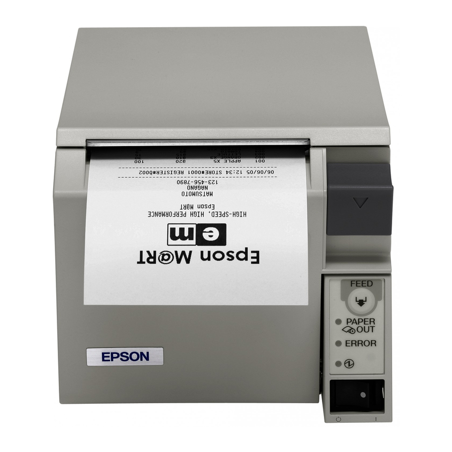
This chapter describes features and specifications of the product. Features The TM-T70 is a receipt printer with high speed printing and a small footprint. With its compact design, it can be placed in a narrow space, such as under a counter, and it also has full front access for easy operability. -
Page 12: Product Configuration
• Wireless LAN interface model (IEEE802.11b) Buzzer • Model with the buzzer function • Model without the buzzer function Color • ECW (Epson Cool White) • EDG (Epson Dark Gray) Accessories Attachments • Roll paper (for operation check) • User’s manual •... -
Page 13: Parts Name And Function
Power switch cover Power Switch Turns the printer on or off. The marks on the switch: ( Before turning on the printer, be sure to check that the AC adapter is connected to the power supply. CAUTION Before turning the printer off, it is recommended to send a power-off command to the printer. -
Page 14: Power Switch Cover
To reset the printer when the power switch cover is installed, insert a long, thin object (such as the end of a paper clip) into the hole in the power switch cover and press the power switch. -
Page 15: Connectors
• While roll paper is fed using the FEED button. • When the printer stops printing due to a paper-end (if an empty paper supply is detected by the roll paper end sensor or if the driver has been set to stop printing when a roll paper near- end is detected) •... -
Page 16: Error Status
Error LED flash code Recovery measure Approx. 160 ms Remove the jammed paper or foreign matter Approx.2.56 s in the printer, close the roll paper cover, send the error recover command, or turn the power on to recover. -
Page 17: Unrecoverable Errors
Unrecoverable Errors Printing is no longer possible when unrecoverable errors occur. The printer must be repaired. Turn off the power immediately when unrecoverable errors occur. CAUTION Error Memory R/W error After R/W checking, the printer does not work correctly. High voltage error The power supply voltage is extremely high. -
Page 18: Nv Memory (Non-Volatile Memory)
NV Memory (Non-Volatile Memory) The printer has NV memory which includes the user NV memory and NV graphics memory that users can use. NV memory can be rewritten about 100,000 times. As a guide, NV memory rewriting should be 10 times or less a day when you program applications. - Page 19 Procedure Open the roll paper cover. While pressing the FEED button, turn the power on. Press the FEED button once. Close the roll paper cover. After instructions are printed, open the roll paper cover. Press the FEED button once. Close the roll paper cover. Turn the power off and on to return to the normal mode.
-
Page 20: Product Specifications
Product Specifications Printing method Cutting method Roll paper (single-ply) Interface Buffer Receive buffer Downloaded buffer NV graphics data NV user memory Barcode/two-dimensional code printing DKD Function Supplied voltage Life Mechanism Thermal head Autocutter MTBF MCBF Temperature/humidity Overall dimensions Weight (mass) Thermal line printing Partial cut (cutting with one point in left edge left uncut) Width: 79.5 ±... -
Page 21: Printing Specifications
Line spacing dpi: dots per inch *1: when the printer prints with the default print density level at 24V and 25°C {77°F}. • Printing speed may be slower, depending on the such items as the data transmission speed. • High speed mode/low power consumption mode can be shifted with a DIP switch (2-3/2-4). -
Page 22: Character Specifications
Character Specifications Number of characters Character structure Character size Font A Font B Note) 1. The actual print character may be smaller than the size shown in the table above, because the above size includes spaces in the font. 2. Characters can be scaled up to 64 times as large as the standard size. 3. -
Page 23: Printable Area
Chapter 1 Product Overview Printable Area In 2-divided energizing, the print position within the printable area of the thermal elements for dots 1 to 256 and 257 to 512 is shifted approximately 0.07 mm {0.0028"} as shown in the figure below in the paper feed direction. In 4-divided energizing, the print position within the printable area of the thermal elements for dots 1 to 96, 97 to 240, 241 to 368, and 369 to 512 is shifted approximately 0.04 mm {0.0016"} as shown in the figure below in the paper feed direction. -
Page 24: Printing And Cutting Positions
Printing and Cutting Positions Manual-cutter position Autocutter blade position Center of the print dotline The values above may vary slightly as a result of paper slack or variations in the paper. Take the notice into account when setting the cutting position of the autocutter. Paper Specifications Paper type Size... -
Page 25: Electrical Characteristics
Electrical Characteristics Supply voltage Current consumption Standby (at 24V, 25°C, normal print density) Operating Chapter 1 Product Overview Low current consumption High speed mode DC24V ± 7% Mean: Approximately 0.1A Maximum 1A for drawer kick-out driving. Mean: Approximately 1.8A Mean: Approximately 1.2A Note) When print ratio is approximately 18% •... -
Page 26: Environmental Conditions
Operating environment range Ambient temperature Approximately 55 dB (Bystander position) Note) The values above are measured in the Epson evaluation condition. The acoustic noise differs depending on the paper used, printing contents, or the setting values such as print speed or print density. -
Page 27: External Dimensions And Mass
Chapter 1 Product Overview External Dimensions and Mass • Height: Approximately 114 mm {4.49"} • Width: Approximately 125 mm {4.92"} • Depth: Approximately 194 mm {7.64"} • Mass: Approximately 1.8 kg {3.96 lb} (except for roll paper) <When the Optional OT-CC70 is installed> 255.5 [Unit: mm]... -
Page 28: Option Specifications
Option Specifications Power Supply Unit (PS-180) Electric Input conditions characteristics Output conditions Case specifications Dimensions (H × W × D) Weight Color Material No specific brominated flame retardants, such as PBBE and PBB, are used in this product. AC cable selection Select an AC cable that satisfies the following conditions. -
Page 29: Setup
Installing the Printer (page 30) Setting the DIP Switches (page 32) Setting the Memory Switches (page 38) Connecting the Printer to the Host Computer (page 39) Connecting the Power Supply Unit (PS-180) (page 47) Connecting the Cash Drawer (page 48) -
Page 30: Installing The Printer
You can install this printer only horizontally. Fix the printer so that it does not move around when you open the roll paper cover and cut roll paper. A tape for fixing the printer is available as an option. (See page 31.) -
Page 31: Important Notes On Installation
• Do not place the printer in dusty locations. • Do not catch cables or foreign matter under the printer. • Do not put anything that has a force of more than 32.7 N {3 kgf} on the top of the printer. Affixing Position of DF-10 When you use the affixing tapes for fixing the printer (Model: DF-10), paste them as shown in the figure below. -
Page 32: Setting The Dip Switches
Otherwise, a short-circuit may cause the printer to malfunction. CAUTION DIP switch settings are enabled only when the power is turned on or the printer is reset via the interface. If the settings are changed after that, the functions will not change. -
Page 33: For Serial Interface
For Serial Interface DIP Switch Bank 1 Function Data reception error Receive buffer capacity Handshaking Word length Parity check Parity selection Transmission speed selections Transmission speed (DIP switch 1-7/1-8) Transmission speed (bps) 115200 (Initial value) 2400, 4800, 9600, 19200, 38400, 57600, 115200 (When setting with a command/Memory Switch Setting Utility) 4800... - Page 34 I/F pin 6 reset signal IF pin 25 reset signal • For DIP switch 2-1 (BUSY condition), see also • Do not change the setting of DIP switches 2-2 and 2-6. Otherwise, the printer may not operate normally. • Offline Receive buffer full •...
-
Page 35: For Interfaces Other Than Serial Interface
IF pin 31 reset signal (Do not change settings) • For DIP switch 2-1 (BUSY condition), see also • Do not change the setting of DIP switches 2-2, 2-6, and 2-7. Otherwise, the printer may not operate normally. Always enabled... -
Page 36: Selecting The Print Density (Dip Switch 2-3/2-4)
Selecting the Print Density (DIP Switch 2-3/2-4) Function Low power consumption mode Print density (Standard) Print density (Darker than standard) Print density (Dark) • If the print density is set to “Darker than standard” or ”Dark” level, printing speed may be reduced. -
Page 37: Selecting The Busy Status
• When the receive buffer is full • When the receive buffer is full or the printer is offline In either case above, the printer enters the BUSY state after power is turned on (including resetting with the interface), and when a self-test is being run. -
Page 38: Setting The Memory Switches
Setting the Memory Switches With the “memory switch (customized value”), which is a software switch of this printer, you can set: • Print density • Print speed • Number of head energizing parts Use the Memory Switch Setting Utility or a command to set the memory switches. -
Page 39: Connecting The Printer To The Host Computer
For Serial Interface Serial interface connection diagram When this printer is connected to the host computer by the serial interface, two connection forms are possible: • Stand alone • Pass-through connection Stand alone This printer is connected to the host computer via the serial port. - Page 40 Connecting the serial interface (RS-232C) cable Be sure to turn off the power supply for both the printer and host computer before connecting the cables. WARNING Insert the interface cable connector firmly into the interface connector on the connector panel.
-
Page 41: For Parallel Interface
For Parallel Interface Parallel interface connection diagram This printer is connected to the host computer via the parallel port. When a customer display (DM-D) is to be connected, connect it to the host computer via the serial port. Serial cable... -
Page 42: For Usb Interface
For USB Interface USB interface connection diagram When this printer is connected to the host computer by the USB interface, two connection forms are possible: • Stand alone • Y connection Stand alone This printer is connected to the host computer via the USB port. When a customer display (DM-D) is to be connected, connect it to the host computer via the serial port. -
Page 43: Connecting The Usb Interface Cable
Connecting the USB interface cable Attach the locking wire saddle at the location shown in the figure below. Put the USB cable through the locking wire saddle. Putting the USB cable through the locking wire saddle, as shown in the figure below, prevents the cable from coming unplugged. -
Page 44: For Lan Interface
LAN interface connection diagram Serial cable TM-T70 A customer display (DM-D series) cannot be connected to the printer when the printer is connected to the host computer. To connect the customer display, connect the printer to the host computer via the serial interface. - Page 45 URLs or ask your dealer: • For customers in North America, go to the following web site: http://www.epsonexpert.com/ • For customers in other countries, go to the following web site: http://www.epson-pos.com/ Switch L E D (Green)
-
Page 46: For Wireless Lan Interface
UB-R02/R03 Technical Reference Guide from one of the following URLs or ask your dealer: • For customers in North America, go to the following web site: http://www.epsonexpert.com/ • For customers in other countries, go to the following web site: http://www.epson-pos.com/ Access point Modular cable Cash drawer... -
Page 47: Connecting The Power Supply Unit (Ps-180)
Connecting the Power Supply Unit (PS-180) Use the PS-180 or an equivalent product as the power supply unit. • Always use the EPSON PS-180 or an equivalent product as the power supply unit. Using a nonstandard power supply can result in electric shock and fire. -
Page 48: Connecting The Cash Drawer
• Leave intervals longer than 4 times the drawer driving pulse when sending it continuously. • Be sure to use the printer power supply (connector pin 4) for the drawer power source. • Do not insert a telephone line into the drawer kick-out connector. -
Page 49: Drawer Circuitry
Drawer kick out connector pin 2 Drawer kick out connector pin 5 Since the buzzer drive signal and the cash drawer drive signal are common in the printer, do not use the same connector pin numbers to output the signal for the buzzer and the cash drawer. -
Page 51: Application Development Information
Use a driver or ESC/POS commands to control the printer. Selecting a Driver Choose one of the drivers, Advanced Printer Driver (APD) or OPOS ADK, depending on the application operating environment. You cannot control the same printer with both of the drivers. -
Page 52: Esc/Pos Command
ESC/POS Command ESC/POS is the Epson original printer command system. With ESC/POS commands, you can directly control all the TM printer functions, but detailed knowledge of printer specifications or combination of commands is required compared to using a driver. To use ESC/POS commands, you need to make a nondisclosure contract first and get the ESC/POS Application Programing Guide. - Page 53 Select/cancel user-defined character set Define user-defined characters Cancel print data in page mode Commands for panel buttons Enable/disable panel buttons Commands for paper sensors Select paper sensor(s) to stop printing Select paper sensor(s) to output paper-end signals Commands for print positions Horizontal tab Set horizontal tab positions Set left margin...
- Page 54 Define downloaded bit image Print downloaded bit image Commands for status Enable/disable Automatic Status Back (ASB) Transmit status Transmit real-time status Commands for barcode Print barcode Set barcode height Set barcode width Select print position of HRI characters Select font for HRI characters Commands for two-dimensional code PDF417: Set the number of columns in the data region PDF417: Set the number of rows...
- Page 55 Generate pulse to drawer Generate pulse to drawer in real-time Execute power-off sequence Clear buffer(s) Enable/disable real-time command Send real-time request to printer Select page mode Select standard mode Set the process ID response Execute test print Select the print speed...
-
Page 56: Software And Manuals
Visual Basic, unlike ordinary Windows drivers. It is not a driver to be used for printing from commercial applications. *2: Describes not Epson’s specific functions, but general information on how to control printers using OPOS ADK (in the chapter “POS Printer”). -
Page 57: Download
Drivers, utilities, and manuals can be downloaded from one of the following URLs. For customers in North America, go to the following web site: http://www.epsonexpert.com/ and follow the on-screen instructions. For customers in other countries, go to the following web site: http://www.epson-pos.com/... -
Page 58: Setting Check Modes
PAPER OUT LED flashes. (The printer is now in the self-test wait mode.): “If you want to continue SELF-TEST printing. Please press FEED button.” To begin the print test again, press the FEED button while the printer is in the self-test wait mode. -
Page 59: Hexadecimal Dumping Mode
Hexadecimal Dumping Mode In the hexadecimal dumping mode, the printer prints the data transmitted from a host computer in hexadecimal numbers and their corresponding characters. Starting hexadecimal dumping Follow the steps below to perform the hexadecimal dumping. • If there is no character corresponding to print data, “.” is printed. -
Page 61: Handling
Otherwise, you may be injured because the manual cutter blade is sharp. • Use roll paper that meets the printer specification. For details about paper specification, see "Paper Specifications" on page 24. • Paper must not be pasted to the roll paper spool. - Page 62 Pull out some roll paper, and make sure that the roll paper is set between the paper guides. Paper guides Close the roll paper cover. Tear off the roll paper.
-
Page 63: Removing Jammed Paper
Remove the jammed paper, reinstall the roll, and close the roll paper cover. Cleaning the Thermal Head Epson recommends cleaning the thermal head periodically (generally every 3 months) to maintain receipt print quality. After printing, the thermal head can be very hot. Do not touch it and let it cool before you clean it. -
Page 64: Preparing For Transport
Preparing for Transport Follow the steps below to transport the printer. Turn off the printer. Confirm that LED is off. Remove the power supply connector. Remove the roll paper. Pack the printer upright. -
Page 65: Appendix
• Yes • No Select one of the following with DIP switch 1-6: • Even • Odd 1 or more bits However, the stop bit for data transfer from the printer is fixed to 1 bit. DSUB 25-pin (female) connector Appendix... -
Page 66: Functions Of Each Connector Pin
• During the self-test. Changing DIP switch 2-8 enables this signal to be used as a reset signal for the printer. The printer is reset if the signal remains at SPACE for a pulse width of 1 ms or more. - Page 67 • When the printer goes from online to offline and the receive buffer is full, XOFF is not CAUTION transmitted. • When DIP switch 1-3 is off, XON is not transmitted as long as the printer is offline, even if a receive buffer full state has been cleared. Appendix...
-
Page 68: Ieee 1284 Parallel Interface
Reverse communication Reverse Mode The transfer of status data from the printer to the host proceeds in the nibble or byte mode. This mode allows data transfer from an asynchronous printer under the control of the host. Data transfers in the nibble mode are made via the existing control lines in units of four bits (a nibble). -
Page 69: Interface Signals
Host Strobe Host/Ptr Data0 (LSB) Host/Ptr Data1 Host/Ptr Data2 Host/Ptr Data3 Host/Ptr Data4 Host/Ptr Data5 Host/Ptr Data6 Host/Ptr Data7 (MSB) Printer Printer Busy Printer Perror Printer Select Host AutoFd Printer Logic-H Nibble Mode Mode HostClk Data0 (LSB) Data1 Data2 Data3... - Page 70 Source Host Init Printer Fault Printer DK_STATUS Printer Host SelectIn NC: None Connect ND: Not Defined • A signal name with a rule above it indicates an “L” active signal. • Bidirectional communications cannot take place, unless all signal names for both sides correspond to each other.
-
Page 71: Usb (Universal Serial Bus) Interface
Unlike RS232C transmission, it cannot spontaneously interrupt data transmission to the host computer. The printer has a 128-byte status data buffer. Statuses that exceed the buffer capacity are cancelled. According to USB 2.0 specifications USB Full-Speed (12 Mbps) -
Page 72: Character Code Tables
Character Code Tables • The character code tables show only character configurations. They do not show the actual print pattern. • “SP” in the table shows a space. Common to All Pages When International character set (See XOFF "International Character Sets" on page "... -
Page 73: Pc437: Usa, Standard Europe]
Page 0 [PC437: USA, Standard Europe] Ç É á í ü æ é Æ ó â ô ú ä ö ñ à ò Ñ å û ç ù ê ÿ ¿ ë Ö ┌ è Ü ¬ ï ¢ ½ î... -
Page 74: Katakana)
Page 1 (Katakana) ┴ ┬ ┤ ├ ¯ ─ │ │ ┌ ┐ └ ┘ ┼ ═ ╞ ╪ ╡ ♠ ♥ ♦ ♣ ● ○ ▓... -
Page 75: Pc850: Multilingual)
Page 2 (PC850: Multilingual) Ç É á í ü æ é Æ ó â ô ú ä ö ñ à ò Ñ å û ç ù ê ÿ ¿ ë Ö ® è Ü ¬ ï ø ½ î £ ¼... -
Page 76: Pc860: Portuguese)
Page 3 (PC860: Portuguese) Ç É ü À é È â ô ã õ à ò Á Ú ç ù Ì ê Ê Õ è Ü Í ¢ Ô £ ì Ù Ã Â Ó á ░ └ ╨ í ▒... -
Page 77: Pc863: Canadian-French)
Page 4 (PC863: Canadian-French) Ç É ¦ ´ ü È é Ê ó â ô ú Â Ë ¨ Ï à ¸ ¶ û ³ ç ù ¯ Î ê ¤ ┌ ë Ô è Ü ¬ ï ¢ ½ î... -
Page 78: Pc865: Nordic)
Page 5 (PC865: Nordic) Ç É ü æ é Æ â ô ä ö à ò å û ç ù ê ÿ ë Ö è Ü ï ø î £ ì Ø Ä Å ƒ á ░ └ ╨ í ▒... -
Page 79: Wpc1252)
Page 16 (WPC1252) € ‘ ¡ ‚ ¢ ƒ £ ¤ • ¥ ¦ § ¨ © « ¬ ® ¯ ° À Ð ± Á Ñ ² Â Ò ³ Ã Ó ´ Ä Ô Å Õ ¶ Æ Ö... -
Page 80: Pc866: Cyrillic #2)
Page 17 (PC866: Cyrillic #2) Г Ф ░ └ ╨ ▒ ┴ ╤ ▓ ┬ ╥ г │ ├ ╙ ┤ ─ ╘ ╡ ┼ ╒ ╢ ╞ ╓ ╖ ╟ ╫ ╕ ╚ ╪ ╣ ╔ ┘ ║ ╩ ┌... -
Page 81: Pc852: Latin2)
Page 18 (PC852: Latin2) Ç É á í ü ĺ é ó â ô ú ä ö ç ł ë Ö Ü î Ä × « » ░ └ ▒ ┴ Ð ▓ ┬ │ ├ Ë ┤ ─ Á ┼... -
Page 82: Pc858: Euro)
Page 19 (PC858: Euro) Ç É ü æ é Æ â ô ä ö à ò å û ç ù ê ÿ ë Ö è Ü ï ø î £ ì Ø Ä × Å ƒ á ░ └ ð í... -
Page 83: User-Defined Page)
Page 255 (User-Defined Page) Appendix... -
Page 84: International Character Sets
International Character Sets Country France Germany U.K. £ Denmark Sweden taly Spain Japan Norway Denmark Spain Latin America Korea Slovenia/Croatia China ASC code (Hex) à ° ç § § Ä Ö Ü Æ Ø Å ¤ É Ä Ö Å Ü...
Need help?
Do you have a question about the TM T70 and is the answer not in the manual?
Questions and answers