
Related Manuals for Cornelius FCB - 2 Flavor


Summary of Contents for Cornelius FCB - 2 Flavor
- Page 1 ® FCB PINNACLE 2 and 4 Flavor Service Manual FCB - 2 Flavor FCB - 4 Flavor Release Date: October 30, 2003 Publication Number: 560007298SER Revision Date: May 07, 2014 Revision: J...
- Page 2 Appropriate safety precautions should be followed and all local safety and construction requirements should be met. To inquire about current revisions of this and other documentation, or for assistance with any Cornelius product contact: www.cornelius.com...
-
Page 3: Table Of Contents
Maintaining Product Quality Cornelius FCB Equipment - Operator Instructions......6 1. Dispensed Product Throughput ........6 2. - Page 4 Transformer Replacement ..........44 Contactor Replacement .
-
Page 5: Safety
Personnel exposed to high concentration of CO gas will experience tremors which are followed rapidly by loss of consciousness. © 2003-2014, Cornelius Inc.. - 1 - Publication Number: 560007298SER... -
Page 6: Shipping And Storage
The magnetic field can affect operation of these devices which may cause bodily injury or death. If disruption of device occurs or operation is adversely effected, immediately move the victim far away from magnet and seek medical assistance. © 2003-2014, Cornelius Inc. - 2 - Publication Number: 560007298SER... -
Page 7: System Overview
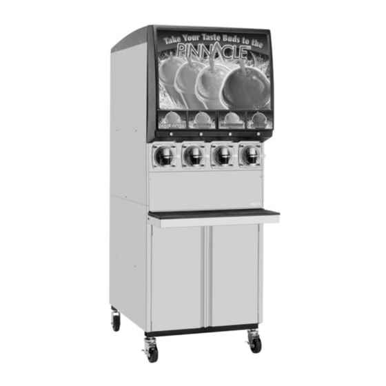
• Control Panel with 5 buttons that control operational and diagnostic functions and settings. Double Refrigeration System Steel Frame Lighted Display Panel Dispensing Valves & Face Plates Control Panel Foam Pack& Motor FIGURE 1 FIGURE 2 © 2003-2014, Cornelius Inc. - 3 - Publication Number: 560007298SER... -
Page 8: Specifications
Brush ..........325216000 © 2003-2014, Cornelius Inc. -
Page 9: Accessories - Optional
Cup holder ......... . 511006000 Cornelius refractometer, 0-30 scale ..... . . 511004000 Transformer. -
Page 10: Operation And Service
2. Programmed Defrost Scheduling The control system in Cornelius FCB equipment includes a function to automatically defrost product in the barrel at programmed times. Programmed defrosts must be scheduled frequently to ensure that product quality within the barrel is maintained. Failure to defrost regularly during periods of low throughput will allow increased ice crystal growth, with a possible decrease in product quality and will cause drive errors. -
Page 11: Sleep Mode Recommendations
Pinnacle 2 and 4 Flavor Service Manual 3. Sleep Mode Recommendations Cornelius recommends programming a sleep for any period of time, over 3 hours, in which the unit will not have any usage. If the programmed sleep is longer than 6 hours, Cornelius also recommends turning the ice bank off in the options menu. -
Page 12: Service
2. Take the following actions from the Control Panel: • From the BARREL STATUS menu, press <MENU>. • From the CHOOSE MODE menu, select <MANUAL DEFROST> and press <GO>. • Select barrel and press <DFRST>. © 2003-2014, Cornelius Inc. - 8 - Publication Number: 560007298SER... - Page 13 • Place barrel # 1 in MOTOR mode (from ON/OFF/MOTOR menu) to start barrel # 1 beater. Allow beater to operate for 5–minutes, then place barrel # 1 in OFF mode (from ON/OFF/MOTOR menu) to stop the beater. © 2003-2014, Cornelius Inc. - 9 - Publication Number: 560007298SER...
- Page 14 10 minutes but not more than 15 minutes. Then place barrel # 1 in OFF mode (from ON/OFF/MOTOR menu) to stop the beater. • Turn barrel # 1 blendonator OFF (from BLENDONATOR menu) to prevent more sanitizing solution from entering the blender tank. © 2003-2014, Cornelius Inc. - 10 - Publication Number: 560007298SER...
-
Page 15: Stainless Steel Double Check Valve Inspection & Cleaning
4. Disassemble valve. 5. Check seat and O-rings. Replace if necessary. 6. Reassemble valve. 7. Check for leaks. Check BRIX Should be done whenever flavors are changed or any service is preformed. © 2003-2014, Cornelius Inc. - 11 - Publication Number: 560007298SER... -
Page 16: Adjustments
The service functions can be secured (locked out) so that the operator will not have access to them. See the Security Lockout Function section under menu 15 for more information. Control Panel Display FIGURE 5 © 2003-2014, Cornelius Inc. - 12 - Publication Number: 560007298SER... - Page 17 It also displays menus of actions that are taken to change the functioning of the machine. Control Panel Display Control Panel Display Area Control Panel Action Buttons FIGURE 6 © 2003-2014, Cornelius Inc. - 13 - Publication Number: 560007298SER...
- Page 18 Pressing a button performs the action labeled just above the button. For example, from the BARREL STATUS menu, pressing button 1 (labeled MENU) displays a menu with more options — pressing button 5 (labeled ERR) displays error messages from the control system. © 2003-2014, Cornelius Inc. - 14 - Publication Number: 560007298SER...
-
Page 19: Control Panel Menu Descriptions
DFRST ..freeze cylinder is presently in DEFROST mode From the BARREL STATUS menu pressing <MENU> displays the CHOOSE MODE menu (menu 2). NOTE: See the Control Panel Error Descriptions for a description of the system errors. © 2003-2014, Cornelius Inc. - 15 - Publication Number: 560007298SER... -
Page 20: Choose Mode
From the CHOOSE MODE menu pressing <BACK> will display the BARREL STATUS menu and press- ing <GO> will display the scroll list item with the pointer in front of it. © 2003-2014, Cornelius Inc. - 16 - Publication Number: 560007298SER... - Page 21 #4 - MOTOR..turn the selected cylinder “MOTOR” (beater bar TURNING and refrigeration INACTIVE) #5 - DOWN..scroll down the menu list © 2003-2014, Cornelius Inc. - 17 - Publication Number: 560007298SER...
- Page 22 #4 - UP ..increase the selected field by 1 (hour, day, etc.) #5 - DOWN..decrease the selected field by 1 © 2003-2014, Cornelius Inc. - 18 -...
- Page 23 2. Press <NEXT> to change the field from HOURS to MINUTES 3. Press <UP> and <DOWN> to change the setting in the field 4. Press <BACK> to save the changes. © 2003-2014, Cornelius Inc. - 19 - Publication Number: 560007298SER...
- Page 24 2. Press <NEXT> to change the field from HOURS to MINUTES 3. Press <UP> and <DOWN> to change the setting in the field 4. Press <BACK> to save the changes. © 2003-2014, Cornelius Inc. - 20 - Publication Number: 560007298SER...
- Page 25 The preset time format used by the system will be used by the SET DEFROST TIME menu. See “3. Sleep Mode Recommendations” on page 7. © 2003-2014, Cornelius Inc. - 21 - Publication Number: 560007298SER...
- Page 26 5. Press <BACK> to save the changes. 6. If desired, repeat steps 2–5 to set more defrost times for the selected day. 7. If desired, repeat steps 1–6 to select different days and times. © 2003-2014, Cornelius Inc. - 22 - Publication Number: 560007298SER...
- Page 27 3. Press <UP> or <DOWN> to increase or decrease the viscosity setting. 4. Press <GO> to move selection pointer back to the cylinder selection. 5. Repeat steps 1 - 4 for remaining cylinders. © 2003-2014, Cornelius Inc.. - 23 - Publication Number: 560007298SER...
- Page 28 NOTE: There is a 2 minute timer to prevent the compressor from short cycling. This timer is can- celed out by a Blendonator actuation. Maximum Viscosity Minimum Viscosity Viscosity Setting Value Value © 2003-2014, Cornelius Inc. - 24 - Publication Number: 560007298SER...
- Page 29 (IB #1). The minimum temperatures for both the barrel and ice bank is -30°F. EVAPORATOR TEMPERATURES Menu Button Descriptions: 1 - BACK ..go back to the previous menu © 2003-2014, Cornelius Inc. - 25 - Publication Number: 560007298SER...
- Page 30 DEFRST #n ..xxxxx HRnumber of hours cylinder “n” has been in auto defrost BLENDR #n ..xxxxx HRnumber of blender cycles on cylinder “n” * = resetting these totals to zero is allowed © 2003-2014, Cornelius Inc. - 26 - Publication Number: 560007298SER...
- Page 31 SYR SOLENOID #Xactivate syrup solenoid BEATER MOTOR #Xmake beater motor turn BRL STAT LITE #X activate cylinder status light (red & green) AUDIBLE ALARM . activate audible alarm on main logic board © 2003-2014, Cornelius Inc. - 27 - Publication Number: 560007298SER...
-
Page 32: Visc Set
VISC SET..viscosity set value ACT ... . actual viscosity value BLENDONATOR . . blendonator mode (ON, OFF) © 2003-2014, Cornelius Inc. - 28 - Publication Number: 560007298SER... - Page 33 #4 - UP ..move selection pointer up #5 - DOWN..move selection pointer down © 2003-2014, Cornelius Inc. - 29 - Publication Number: 560007298SER...
-
Page 34: Options
15 minutes after last button press. Once lockout is engaged the display goes to BARREL STATUS menu, and the MENU button (#1) is disabled. Security is disengaged by pressing button #1 (far left) and #5 (far right) at the same time. © 2003-2014, Cornelius Inc. - 30 - Publication Number: 560007298SER... - Page 35 Open the valve at the end of the sample tube. Press GO and wait 3-5 seconds. The product pump will pump product for approximately 3 seconds. After sample is dispensed Press Go twice more to dispense product two more times. Discard these first three samples. © 2003-2014, Cornelius Inc. - 31 - Publication Number: 560007298SER...
- Page 36 #4 - UP ..move selection pointer up #5 - DOWN..move selection pointer down © 2003-2014, Cornelius Inc. - 32 - Publication Number: 560007298SER...
- Page 37 #4 - UP ..move selection pointer up #5 - DOWN..move selection pointer down © 2003-2014, Cornelius Inc. - 33 - Publication Number: 560007298SER...
- Page 38 The VOLT menu displays line voltage at the contactor. The voltage will be displayed in Volts RMS. VOLT Menu Button Descriptions: #1 - BACK ..go back to the previous menu © 2003-2014, Cornelius Inc. - 34 - Publication Number: 560007298SER...
- Page 39 #4 - NEXT ..display the next (later) error log entry #5 - PREV ..display previous (earlier) error log entry. © 2003-2014, Cornelius Inc. - 35 -...
-
Page 40: Control Panel Error Descriptions
F for more than 2400 seconds, the control system will dis- play a SENSOR ERROR for the Ice Bank. NOTE: The 5600075xx Series controls will have an upper limit of 150°F for barrel sensors. © 2003-2014, Cornelius Inc. - 36 - Publication Number: 560007298SER... - Page 41 Pinnacle 2 and 4 Flavor Service Manual © 2003-2014, Cornelius Inc. - 37 - Publication Number: 560007298SER...
-
Page 42: Component Service
Pinnacle 2 and 4 Flavor Service Manual COMPONENT SERVICE NOTE: IF the LED on display panel is ON please see Tech Tip TT-04-13, on www.cornelius.com, for information on the Production Safety System Response. The following are procedures for servicing the major components of the Pinnacle. - Page 43 ON, then turn the product cylinder supply valve ON, bleed the cylinder, and use the control panel to turn the cylinder ON. There is a short delay before the beater bar starts rotating. © 2003-2014, Cornelius Inc. - 39 - Publication Number: 560007298SER...
-
Page 44: Dc Control Drive Motor Board Replacement - Emerson
5. Secure the new board in place and reconnect the wiring. 6. If the Main Board was replaced, program the previous setting for time, defrost, sleep, walk-up, and viscosity. Main Boards 7. Re-attach the panels. FIGURE 36 © 2003-2014, Cornelius Inc. - 40 - Publication Number: 560007298SER... -
Page 45: Chip Change Procedure
The purpose of this notice is to describe the proper method for changing a chip on the master board of a Cornelius machine should it become necessary. NOTE: Static electricity can destroy sensitive electronic circuits. Always wear static straps or keep yourself grounded to the machine while working in the electronic boards. -
Page 46: Dc Inverter Board Replacement - Baldor
5. Secure the new board in place and reconnect the wiring. Main Boards FIGURE 38 6. If the Main Board was replaced, program the previous setting for time, defrost, sleep, walk-up, and viscosity. 7. Re-attach the panels. © 2003-2014, Cornelius Inc. - 42 - Publication Number: 560007298SER... -
Page 47: Display Board Replacement
6. Install the new ballast and ballast cover (2 screws each). Flip the merchandiser back down and go through a normal start-up procedure. FIGURE 41 © 2003-2014, Cornelius Inc. - 43 - Publication Number: 560007298SER... -
Page 48: Transformer Replacement
3. Unfasten the strap (1 screw). 4. Replace all start and run components, note connection locations. Reassemble, re-connect power, and go through a normal startup procedure. Run capacitor Start capacitor FIGURE 43 © 2003-2014, Cornelius Inc. - 44 - Publication Number: 560007298SER... -
Page 49: Pump Motor Replacement
3. Reverse the procedure to install new motor. 2 screws on each side Ground screw FIGURE 45 YRUP ATER ALVE EPLACEMENT 1. Follow the instruction (629088599INS) included with the replacement kit, also located on www.cornelius.com. © 2003-2014, Cornelius Inc. - 45 - Publication Number: 560007298SER... -
Page 50: Co2 Regulator Replacement
7. Reverse the procedure to install new blendonator. Be sure and check for leaks after pressurizing the system. 8. Bleed air from blendonator using pressure relief valve. 9. Run through the normal start-up procedure. © 2003-2014, Cornelius Inc. - 46 - Publication Number: 560007298SER... -
Page 51: Hy-Pot Test Procedure
FIGURE 50. Compressor contactor pushed in during test. 5. Press “Test” button on the Hy-Pot tester. 6. Record result (Pass or Fail) as indicated by the display on the Hy-Pot tester. © 2003-2014, Cornelius Inc. - 47 - Publication Number: 560007298SER... -
Page 52: Hall Effect Sensor Diagnosis & Replacement - Baldor
#1. Keep the beater bar Rotate slowly. engaged with the drive magnet in the back of the freeze cylinder. You will be slowly turning the beater bar by hand. FIGURE 52 © 2003-2014, Cornelius Inc. - 48 - Publication Number: 560007298SER... -
Page 53: Dc Stator Test - Emerson
Test stator and connecting wiring at the inverter board. 2. Check the resistance of all 3 (yellow, red, and blue) of the terminals. FIGURE 55 The correct reading should be approximately 37 ohms. FIGURE 56 FIGURE 57 © 2003-2014, Cornelius Inc. - 49 - Publication Number: 560007298SER... -
Page 54: Dc Stator Test - Baldor
Test stator and connecting wiring at the inverter board. FIGURE 58 2. Check the resistance of all three of the terminals. FIGURE 59 The correct reading should be approximately 80ohms. FIGURE 60 FIGURE 61 © 2003-2014, Cornelius Inc. - 50 - Publication Number: 560007298SER... -
Page 55: Dc Stator Assembly Replacement
13. Reinstall the faceplate by pressing until it contacts the front of the cylinder and then install the washers and nuts (finger tight only). 14. Re-connect the power and go through the normal start-up procedure. © 2003-2014, Cornelius Inc. - 51 - Publication Number: 560007298SER... -
Page 56: Dc Stator Assembly Replacement - Baldor
Replace thermostat, be careful not to over tighten the brass insert, the threads may snap off inside the steel boss. Replace foam insulation. Reconnect wire harness. Reconnect product supply line. © 2003-2014, Cornelius Inc. - 52 - Publication Number: 560007298SER... -
Page 57: Condenser Fan Motor Replacement (Integral Only)
7. Reverse the procedure to install new motor. Screws FIGURE 68 ONDENSER ILTER EPLACEMENT NTEGRAL 1. Slide filters out of tracks right and left side. 2. Clean or replace. 3. Re-install. FIGURE 69 © 2003-2014, Cornelius Inc. - 53 - Publication Number: 560007298SER... -
Page 58: Foam Pack Replacement
Unsweat fittings from the back of the foam pack. Lift the foam pack out the front of the unit. 14. Reverse the procedure to install new foam pack. Replace the dryer. Evacuate and recharge the system. © 2003-2014, Cornelius Inc. - 54 - Publication Number: 560007298SER... -
Page 59: Compressor Replacement
2. Reclaim refrigerant. 3. Rebuild the hot gas valve per the manufacturer’s instructions. 4. Replace the dryer. Evacuate and recharge the system. Coil screw Hot gas valve body (inside) FIGURE 73 © 2003-2014, Cornelius Inc. - 55 - Publication Number: 560007298SER... -
Page 60: Pulse Valve Replacement
2. Turn off water source then bleed pressure from water feed line at the rear disconnect. 3. Unscrew cap and remove Strainer. 4. Clean Strainer and reassemble in the reverse order. Be sure and check for leaks after pressurizing the system. © 2003-2014, Cornelius Inc. - 56 - Publication Number: 560007298SER... -
Page 61: Merchandiser Lamp Removal And Installation
NOTE: Pulling down on lamp to disengage pins may result in damage to lampholders and spring clips. Reflector Surface Lampholder FIGURE 78 © 2003-2014, Cornelius Inc. - 57 - Publication Number: 560007298SER... -
Page 62: Installation
(see FIGURE 81). NOTE: Pushing up on lamp to engage pins may result in damage to lampholders. Pins MUST be Fully Engaged!! FIGURE 81 © 2003-2014, Cornelius Inc. - 58 - Publication Number: 560007298SER... - Page 63 Locks FIGURE 82 FIGURE 83 demonstrates lampholder with lock properly engaged (lamp omitted for clarity). WARNING: For proper and effective lamp func- tion, locks must be completely engaged. FIGURE 83 © 2003-2014, Cornelius Inc. - 59 - Publication Number: 560007298SER...
-
Page 64: Troubleshooting
Freeze up. 3 - Check for leaking pulse valve. 4 - Defective binding magnet 5 - Broken beater bar. B. Bad inverter board (Emerson). B. Test and replace as necessary. © 2003-2014, Cornelius Inc. - 60 - Publication Number: 560007298SER... -
Page 65: Troubleshooting Product Not Cold
D. Check resistance of compressor protector “open”. windings and check incoming line E. Open or shorted compressor voltage. windings. E. Check resistance of compressor Bad control board. windings. Troubleshoot, replace if neces- sary. © 2003-2014, Cornelius Inc. - 61 - Publication Number: 560007298SER... - Page 66 Sensors A. Bad connection. A. Correct wiring. B. Bad sensor. B. Replace sensor. C. Sensor out of position. C. Reposition sensor and clip. D. Defective product delivery board. D. Replace. © 2003-2014, Cornelius Inc. - 62 - Publication Number: 560007298SER...
-
Page 67: Appendix A - Historic Brix Procedures
Make sure the status of all cylinders is OFF. Press MENU, press UP until BRIX is selected, press GO, select cylinder to be BRIXed. NOTE: Pressing CANCLE will stop the process. © 2003-2014, Cornelius Inc. - 63 - Publication Number: 560007298SER... - Page 68 9. Repeat procedure for additional freeze cylinders. 10. Turn the freeze cylinder shutoff valves to the ON position. Press MENU, press UP until blendonator is selected, press GO, select the desired cylinder, press ON. © 2003-2014, Cornelius Inc. - 64 - Publication Number: 560007298SER...
- Page 69 Wait 10 – 15 minutes and test the product. NOTE: Make sure the controller is programmed before pressing ON. 16. Install the second side panel, splash panel, drip tray, and top cover. © 2003-2014, Cornelius Inc. - 65 - Publication Number: 560007298SER...
-
Page 70: Section 2: Shut-Off Valve And Blendonator Outlet Brix Sample Tube Procedure
14. Repeat steps 11-13 until the product BRIX is within specification. 15. Repeat steps 8-14 until Blendonator #2 product BRIX is within specification. 16. Scroll to the BLENDONATOR menu and turn both Blendonators ON. © 2003-2014, Cornelius Inc. - 66 - Publication Number: 560007298SER... -
Page 71: Valve Torque And Staking
Delta and Motorman valve configurations and for staking the shank nut (Delta valve configuration ONLY) are detailed in this Procedure. The Cornelius tool (part num- ber 620711709) to be used to torque the shank nut can be purchased by contacting BEVCORe at 763- 488-3000. -
Page 72: Delta Valve
NOTE: This procedure is used for the stainless steel Delta valve only. DO NOT use on plastic Motorman Valve threads. © 2003-2014, Cornelius Inc. - 68 - Publication Number: 560007298SER... - Page 73 This is what the Delta shank nut clear- ance should look like. • Shank nut surface flush-to-0.023” above Valve surface. Shank Nut Surface Staking mark on threads inside notch in Shank Nut. © 2003-2014, Cornelius Inc. - 69 - Publication Number: 560007298SER...
-
Page 74: Motorman Valve
Valve Surface proper thread engagement. This is what the Motorman shank nut clearance should look like. • Shank nut surface 0.083” below valve surface. Shank Nut Surface © 2003-2014, Cornelius Inc. - 70 - Publication Number: 560007298SER... - Page 76 Cornelius Inc. www.cornelius.com...
Need help?
Do you have a question about the FCB - 2 Flavor and is the answer not in the manual?
Questions and answers