Table of Contents
Advertisement
Quick Links
HORIZON
FULL D D EPTH G G AS F F IRE
INSTALLATION A A ND U U SER I I NSTRUCTIONS
All i i nstructions m m ust b b e h h anded t t o u u ser f f or s s afekeeping
Revision A - 06/05
Country(s) of destination - GB/IE
Focal Point Fires plc, Avon Trading Park, Christchurch, Dorset BH23 2BT
Tel: 01202 499330
Fax: 01202 499326
www.focalpointfires.co.uk
e-mail: sales@focalpointfires.co.uk
Advertisement
Table of Contents

Related Manuals for FocalPoint HORIZON


Summary of Contents for FocalPoint HORIZON
- Page 1 HORIZON FULL D D EPTH G G AS F F IRE INSTALLATION A A ND U U SER I I NSTRUCTIONS All i i nstructions m m ust b b e h h anded t t o u u ser f f or s s afekeeping...
- Page 2 Horizon...
- Page 3 INST T ALLAT T ION I I NST T RUCT T IONS P P relim m in n ary N N otes B B efore I I n n stallation n This appliance is an Inset Live Fuel Effect appliance which provides radiant warmth utilising the latest type burner technology.
-
Page 4: Table Of Contents
Sec c tion Contents s Pag g e N N o. Pag g e N N o. Sec c tion Contents s Important Notes 10.0 Gas Supply Appliance Data 11.0 Fitting the Firebox Installation Requirements 11.1 Cable Fixing Site Requirements 11.2 Gas Connection Ventilation... -
Page 5: Appliance D D Ata
APPLIANCE D D ATA Manual Control Version Gas Group G20 Natural Gas CAT I2H Inlet Pressure 20 mbar Max Energy Input (gross) 6.2 kW Min Energy Input (gross) 3.5 kW Pilot Energy Input (gross) 166 W Setting Pressure (cold) 17.5mbar (+/- 0.75mbar) Main Injector Burner Stereo size 77 Gas Inlet Connection... -
Page 6: Site Requirements
SITE R R EQUIREMENTS ( ( continued) This appliance requires a natural draught flue system which may be one of the following; 225mm x 225mm (9in x 9in) brick or stone. 175mm (7in) minimum diameter lined brick or stone. 175mm (7in) minimum diameter twin wall flue conforming to BS 715. Any existing under grate draught device must be sealed off. -
Page 7: Ventilation
VENTILATION No purpose provided ventilation is normally required for this appliance. The requirements of other appliances operating in the same room or space must be taken into consideration when assessing ventilation. If spillage is detected when commissioning the appliance then amongst other problems there may be insufficient natural ventilation for the correct operation of the flue. -
Page 8: Unpacking T T He A A Ppliance
UNPACKING T T HE A A PPLIANCE Stand the carton right way up, cut the strapping bands and remove the top end cap. Read all the instructions before continuing to unpack or install this appliance. Remove the box containing the fire front, and the bags and boxes containing the ceramic parts. Remove the card- board packing pieces, and any bags containing other fittings or parts. -
Page 9: Preparing The Opening
PREPARING T T HE O O PENING Before installing the fire, check the flue using a smoke pellet. All of the smoke should travel up the flue and exit correctly from the terminal. If problems are found, DO NOT fit the fire until corrective action is completed. Protect the decorative hearth whilst pushing the firebox in and out of the opening. -
Page 10: Fitting The Firebox
10.0 GAS S S UPPLY R R OUTING ( ( continued) The gas pipe must be suitably protected where it passes through fireplace openings. An isolator cock or restric- tor elbow must be fitted to the incoming supply to facilitate servicing. Any sleeving should be sealed to the pipe at its ends. -
Page 11: Gas Connection
11.2 GAS CONNECTION Refit the burner tray into the firebox, fit the two screws through the locating holes in the tray legs, and tighten. Purge the gas supply thoroughly to remove air and dirt/debris BEFORE connection. Now disconnect the inlet restrictor elbow from the inlet pipe. -
Page 12: Spark Failure
14.2 SPARK FAILURE The gap between the spark electrode and the pilot should be 3.5 - 4.5mm to produce a good spark. There should be no need to adjust this. If under any circumstances the electric spark fails, the pilot may be lit manually by pro- ceeding with the ignition sequence as previously described, and after turning the control knob through the spark position, the knob should be held in and the pilot lit with a taper. -
Page 13: Servicing
14.5 TESTING FOR SPILLAGE ( ( continued) A.25mm down Fireplace Opening Cross section of smoke match tube from opening 25mm from front of opening. Tube Disregard Crimp Match outer 50mm Make a smoke match tube from 10mm either side of diameter tube. - Page 14 15.1 CLEANING T T HE C C ERAMIC F F UEL B B ED Remove the ceramic components. Gently clean in the open air. Be careful not to create dust from the pebbles. Where necessary replace damaged components with genuine spares. Seal scrap components in plastic bags and dispose of at proper refuse sites as directed.
-
Page 15: Troubleshooting Guide
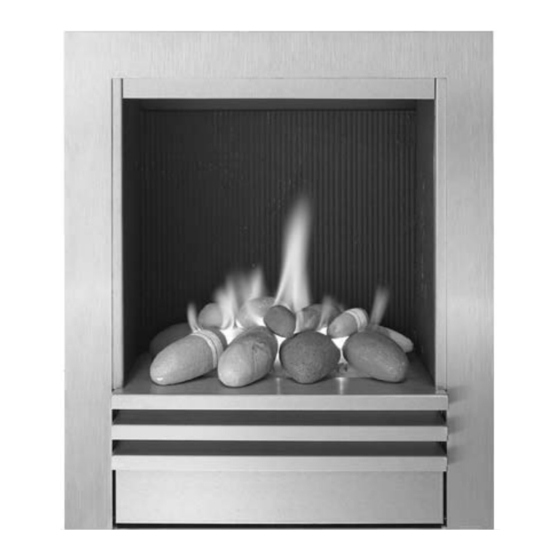
16.0 TROUBLESHOOTING G G UIDE Fire s s parks s b b ut p p ilot d d oes s n n ot l l ig g ht No gas to fire, check isolators are open. Pipework blockage, clean out. Air not fully purged, repurge supply or wait longer. - Page 16 USER INST T RUCT T IONS Sec c tion Contents s Pag g e N N o. Important Notes Clearances to Combustibles Ventilation Fuel bed layout Operating Instructions Flue Spillage Monitoring System Cleaning List of Spares IMPORTANT N N OTES The installation of this fire MUST only be carried out by a competent person (such as a CORGI registered fitter) in accordance with the Gas Safety (Installation and Use) Regulations 1998, the relevant British Standards, Codes of Practice, the Building Regulations and the manufacturers’...
- Page 17 CLEARANCES T T O C C OMBUSTIBLES ( ( continued) Any combustible side walls must be at least 500mm to the side of the radiant heat source. As with all heating appliances, any decorations, soft furnishings, and wall coverings (i.e. flock, blown vinyl and embossed paper) positioned too close to the appliance may discolour or scorch.
- Page 18 FUEL BED LAYOUT (continued) 5. Place the pebble ‘D’ onto the peg ‘D’ on the matrix as shown. When pebble ‘C’ is in position this pebble can only fit onto the peg one way - do not force it on. 6.
- Page 19 FUEL BED LAYOUT (continued) 10. Place the pebbles ‘I’ and ‘J’ onto the four large pebbles on the left hand side of the fuel bed as shown. 11. Place the pebbles ‘K’, ‘L’ and ‘M’ onto the four large pebbles on the left hand side of the fuel bed as shown.
-
Page 20: List Of Spares
CLEANING Before c c arrying o o ut a a ny o o f t t he f f ollowing o o perations, e e nsure t t hat t t he f f ire i i s O O FF a a nd c c ompletely c c old. Debris that may form on the firebed should be periodically removed by a competent person.
Need help?
Do you have a question about the HORIZON and is the answer not in the manual?
Questions and answers