Table of Contents
Advertisement
Quick Links
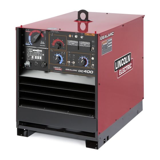
IDEALARC
For use with machines having Code Numbers:
This manual covers equipment which is no
longer in production by The Lincoln Electric Co.
Speci cations and availability of optional
features may have changed.
Safety Depends on You
Lincoln arc welding and cutting
equipment is designed and built
with safety in mind. However,
your overall safety can be
increased by proper installation
... and thoughtful operation on
your part. DO NOT INSTALL,
OPERATE OR REPAIR THIS
EQUIPMENT WITHOUT READ-
ING THIS MANUAL AND THE
SAFETY PRECAUTIONS CON-
TAINED THROUGHOUT. And,
most importantly, think before
you act and be careful.
• Sales and Service through Subsidiaries and Distributors Worldwide •
Cleveland, Ohio 44117-1199 U.S.A. TEL: 216.481.8100 FAX: 216.486.1751 WEB SITE: www.lincolnelectric.com
DC-400
®
9847 thru 9852, 9854, 9855, 9857, 10008,
10275, 10276, 10859, 10880, 11083, 11084,
11277, 11278, 11279 11348, 11349, 11350,
11351, 11352, 11353, 11567
OPERATORʼS MANUAL
• World's Leader in Welding and Cutting Products •
Copyright © Lincoln Global Inc.
IM474-E
February, 2011
Advertisement
Table of Contents

Related Manuals for Lincoln IDEALARC DC-400


Summary of Contents for Lincoln IDEALARC DC-400
- Page 1 10275, 10276, 10859, 10880, 11083, 11084, 11277, 11278, 11279 11348, 11349, 11350, This manual covers equipment which is no longer in production by The Lincoln Electric Co. 11351, 11352, 11353, 11567 Speci cations and availability of optional features may have changed.
- Page 2 351040, Miami, Florida 33135 or CSA Standard W117.2-1974. A Free copy of “Arc Welding Safety” booklet E205 is available from the Lincoln Electric Company, 22801 St. Clair Avenue, Cleveland, Ohio 44117-1199. BE SURE THAT ALL INSTALLATION, OPERATION, MAINTENANCE AND REPAIR PROCEDURES ARE PERFORMED ONLY BY QUALIFIED INDIVIDUALS.
-
Page 3: Electric Shock Can Kill
SAFETY ARC RAYS can burn. ELECTRIC SHOCK can 4.a. Use a shield with the proper filter and cover kill. plates to protect your eyes from sparks and 3.a. The electrode and work (or ground) circuits the rays of the arc when welding or observing are electrically “hot”... - Page 4 SAFETY WELDING and CUTTING CYLINDER may explode SPARKS can if damaged. cause fire or explosion. 7.a. Use only compressed gas cylinders 6.a. Remove fire hazards from the welding area. containing the correct shielding gas for the If this is not possible, cover them to prevent process used and properly operating the welding sparks from starting a fire.
- Page 5 SAFETY 5. Toujours porter des lunettes de sécurité dans la zone de PRÉCAUTIONS DE SÛRETÉ soudage. Utiliser des lunettes avec écrans lateraux dans les zones où lʼon pique le laitier. Pour votre propre protection lire et observer toutes les instructions et les précautions de sûreté...
- Page 6 Electric for advice or information about their use of our products. We respond to our customers based on the best information in our posses- sion at that time. Lincoln Electric is not in a position to warrant or guarantee such advice, and assumes no liability, with respect to such infor- mation or advice.
-
Page 7: Table Of Contents
TABLE OF CONTENTS Page Installation .......................Section A Technical Specifications ..................A-1 Safety Precautions ..................A-2 Correct Operational use ..................A-2 Stacking and Lifting..................A-2 Input Power Connections ................A-2 Output Connections ..................A-3 Installation of Field Installed Options ..............A-3 K843 Amptrol Installation Instructions ..............A-4 Installation of Equipment Requied for Recommended Processes..A-5 Thru A-6 ––––––––––––––––––––––––––––––––––––––––––––––––––––––––––––––––––––––––... - Page 8 INSTALLATION TECHNICAL SPECIFICATIONS – DC-400 (1) Based upon 10 minute time period (i.e., for 60% duty cycle, it is 6 minutes on an 4 minutes off). Use only Bussmann Super-Lag fuses specified. Other fuses may not protect the welder and may cause overheating and possible fire damage.
-
Page 9: Installation
INSTALLATION Failure to observe these precautions can result in excessive operating temperatures and nuisance shut- SAFETY PRECAUTIONS down of the machine. WARNING LIMIT ON STACKING ELECTRIC SHOCK can kill. • Do not touch electrically live parts or WARNING electrode with skin or wet clothing. FALLING EQUIPMENT can cause •... -
Page 10: Output Connections
An optional “remote out control” is available. The page. K857 or K857-1 are the same remote control options that are used on other Lincoln power sources. The K857 or K857-1 consist of a control box with 25 feet (7.6 meters) or 100 feet (30.3 meters). - Page 11 INSTALLATION...
-
Page 12: Installation Of Equipment Requied For Recommended Processes
The two terminals on the right side of the box are for connection of work and electrode for stick or A cover (Lincoln Electric Part Number S17062-3) is air carbon arc. The output terminals are protected available for the unused 14-pin connector to protect it against accidental contact by hinged covers. - Page 13 INSTALLATION The operation of the switch is as follows: To stick WORK electrode holder or A semiautomatic or automatic wire feed unit electrode air carbon and work cables are connected to the terminals on the To semi- arc torch ELECTRODE left side of the box.
-
Page 14: Safety Precautions
OPERATION SAFETY PRECAUTIONS OUTPUT CONTROL DIAL WARNING Output (Control) ELECTRIC SHOCK can kill. • Have an electrician install and ser- vice this equipment. • Turn the input power off at the fuse box before working on equipment. Increase/Decrease of • Do not touch electrically hot parts. Output (Voltage or •... - Page 15 OPERATION OUTPUT TERMINALS SWITCH RATING PLATE Three Phase Power Output (Voltage) Transformer Rectifier Remote On/Off ARC FORCE CONTROL DIAL Rectified DC Output Shielded Metal Arc Welding Constant Voltage Characteristic Gas Tungsten Arc Welding MODE SWITCH Do not switch if Arc Force Current output voltage or current is present.
- Page 16 OPERATION RATING PLATE (Continued) Designates welder complies with National Electrical Manufacturers NEMA EW 1 Association requirements EW 1. (Export Model only) Designates welder complies with International Electrotechnical IEC 60974-1 Commission requirements 60974-1. (European model only) Three Phase Power Transformer Rectifier Rectified DC Output Constant Voltage Characteristic Constant Current Characteristic Line Connection...
-
Page 17: General Machine Description
OPERATION GENERAL MACHINE DESCRIPTION OUTPUT TERMINALS “ON” OR OUTPUT TERMI- NALS “REMOTE” The DC-400 is an SCR controlled three phase DC This switch provides an alternative to the “2 to 4” power source. It is designed with a single range jumpering function by energizing the machineʼs output potentiometer control. -
Page 18: Power Source Operation And Controls
OPERATION POWER SOURCE OPERATION AND OUTPUT CONTROL “LOCAL-REMOTE” SWITCH © CONTROLS The OUTPUT CONTROL toggle switch on the control panel labeled “LOCAL-REMOTE” gives the operator WARNING the option of controlling the output at the machine ELECTRIC SHOCK control panel or at a remote station. For remote con- can kill. - Page 19 OPERATION OUTPUT TERMINALS SWITCH In this position, the dynamic characteristics of the machine under welding conditions provide optimum The OUTPUT TERMINALS toggle switch on the con- welding characteristics for Innershield ® welding, other trol panel labeled “REMOTE - ON” allows the welder open arc processes including short arc MIG welding, output to be activated remotely or to be always on.
- Page 20 OPERATION Terminal Strip Connections Terminal strip TS2 located behind the hinged control panel on the front of the power source supplies 110-115V AC. A 10 amp circuit breaker protects this circuit. Note that this 110-115V AC is also available in the 14-pin connector on the Domestic and Export models.
-
Page 21: Auxiliary Power Connections
OPERATION AUXILIARY POWER CONNECTIONS The SCR snubber board consists of a capacitor and The power source is equipped to furnish nominally resistor connected across each SCR and across the 110-115 volt AC and 40-42 volt AC auxiliary power for entire bridge and MOVʼs to protect the control circuitry operating wire feeding equipment, etc. -
Page 22: Stick Welding
OPERATION The case rear, top section, is equipped with a remov- DIODE OPTION able access panel. This provides easy access to the input contactor, easy connection and reconnection of The DC-400 Diode option is required to utilize the cold input leads, and easy access for service or inspection. start and cold electrode sensing features of the NA-3, NA-5 or NA-5R. -
Page 23: Accessories
An optional “remote output control” is available. This is any LN-9 having an L6043-1 Power PC Board. the same remote control that is used on the Lincoln R3R, and DC-600 power sources (K775). The K775 2) DC-400 is used with an LN-22 equipped with an consists of a control box with 28 ft (8.5m) of four con-... - Page 24 ACCESSORIES AMPTROL™ ADAPTER CABLE (K843) For easy moving of the machine, optional undercar- A five wire cable, 12” (.30m) long, is available for easy riages are available with either steel (K817) or rubber connection of standard K963 Hand Amptrol or K870 tired (K817R) wheels or a platform undercarriage Foot Amptrol.
-
Page 25: Maintenance
MAINTENANCE SAFETY PRECAUTIONS WARNING ----------------------------------------------------------------------- ELECTRIC SHOCK can kill. • Have an electrician install and ser- vice this equipment. • Turn the input power off at the fuse box before working on equipment. • Do not touch electrically live parts or electrode with skin or wet clothing. -
Page 26: Troubleshooting
HOW TO USE TROUBLESHOOTING GUIDE WARNING Service and Repair should only be performed by Lincoln Electric Factory Trained Personnel. Unauthorized repairs performed on this equipment may result in danger to the technician and machine operator and will invalidate your factory warranty. For your safety and to avoid Electrical Shock, please observe all safety notes and precautions detailed throughout this manual. - Page 27 CAUTION If for any reason you do not understand the test procedures or are unable to perform the tests/repairs safely, contact your Local Lincoln Authorized Field Service Facility for technical troubleshooting assistance before you proceed. IDEALARC® DC-400...
- Page 28 2. Replace. (S1). CAUTION If for any reason you do not understand the test procedures or are unable to perform the tests/repairs safely, contact your Local Lincoln Authorized Field Service Facility for technical troubleshooting assistance before you proceed. IDEALARC® DC-400...
- Page 29 Replacing PC Boards. CAUTION If for any reason you do not understand the test procedures or are unable to perform the tests/repairs safely, contact your Local Lincoln Authorized Field Service Facility for technical troubleshooting assistance before you proceed. IDEALARC® DC-400...
- Page 30 CAUTION If for any reason you do not understand the test procedures or are unable to perform the tests/repairs safely, contact your Local Lincoln Authorized Field Service Facility for technical troubleshooting assistance before you proceed. IDEALARC® DC-400...
-
Page 31: Procedure For Replacing Pc Boards
5. If either step (3) or step (4) fails, replace the switch. CAUTION If for any reason you do not understand the test procedures or are unable to perform the tests/repairs safely, contact your Local Lincoln Authorized Field Service Facility for technical troubleshooting assistance before you proceed. IDEALARC® DC-400... - Page 32 Steps 2 and 3. CAUTION If for any reason you do not understand the test procedures or are unable to perform the tests/repairs safely, contact your Local Lincoln Authorized Field Service Facility for technical troubleshooting assistance before you proceed. IDEALARC® DC-400...
- Page 33 DIAGRAMS IDEALARC® DC-400...
- Page 34 DIAGRAMS WIRING DIAGRAM FOR CODES 9847 THRU 9852, 9854, 9855, 9857, 10008, 10275, 11350, 11351 IDEALARC® DC-400...
- Page 35 DIAGRAMS WIRING DIAGRAM FOR CODES 10859, 10880,11083, 11084 L9107 IDEALARC® DC-400...
- Page 36 DIAGRAMS WIRING DIAGRAM FOR CODE 9847, 11349 IDEALARC® DC-400...
- Page 37 DIAGRAMS WIRING DIAGRAM FOR CODES 11277, 11278 AND 11279, 11348, 11352, 11353 and 11567 IDEALARC® DC-400...
- Page 38 NOTES IDEALARC® DC-400...
- Page 39 NOTES IDEALARC® DC-400...
- Page 40 Do not touch electrically live parts or Keep flammable materials away. Wear eye, ear and body protection. • • • WARNING electrode with skin or wet clothing. Insulate yourself from work and • ground. Spanish No toque las partes o los electrodos Mantenga el material combustible Protéjase los ojos, los oídos y el •...
- Page 41 Keep your head out of fumes. Turn power off before servicing. Do not operate with panel open or • • • WARNING Use ventilation or exhaust to guards off. • remove fumes from breathing zone. Spanish Los humos fuera de la zona de res- •...
- Page 42 • World's Leader in Welding and Cutting Products • • Sales and Service through Subsidiaries and Distributors Worldwide • Cleveland, Ohio 44117-1199 U.S.A. TEL: 216.481.8100 FAX: 216.486.1751 WEB SITE: www.lincolnelectric.com...
Need help?
Do you have a question about the IDEALARC DC-400 and is the answer not in the manual?
Questions and answers