Table of Contents
Advertisement
Quick Links
Operator's Manual
TCV400
Register your machine:
www.lincolnelectric.com/register
Authorized Service and Distributor Locator:
www.lincolnelectric.com/locator
Save for future reference
Date Purchased
Code:
(ex: 10859)
Serial:
(ex: U1060512345)
IM10063-A
| Issue D ate 12-Feb
© Lincoln Global, Inc. All Rights Reserved.
For use with machines having Code Numbers:
11727, 11838
Advertisement
Table of Contents

Related Manuals for Lincoln TCV400


Summary of Contents for Lincoln TCV400
- Page 1 For use with machines having Code Numbers: 11727, 11838 Register your machine: www.lincolnelectric.com/register Authorized Service and Distributor Locator: www.lincolnelectric.com/locator Save for future reference Date Purchased Code: (ex: 10859) Serial: (ex: U1060512345) IM10063-A | Issue D ate 12-Feb © Lincoln Global, Inc. All Rights Reserved.
- Page 2 351040, Miami, Florida 33135 or CSA Standard W117.2-1974. A Free copy of “Arc Welding Safety” booklet E205 is available from the Lincoln Electric Company, 22801 St. Clair Avenue, Cleveland, Ohio 44117-1199. BE SURE THAT ALL INSTALLATION, OPERATION, MAINTENANCE AND REPAIR PROCEDURES ARE PERFORMED ONLY BY QUALIFIED INDIVIDUALS.
-
Page 3: Electric Shock Can Kill
SAFETY ARC RAYS can burn. ELECTRIC SHOCK can 4.a. Use a shield with the proper filter and cover kill. plates to protect your eyes from sparks and 3.a. The electrode and work (or ground) circuits the rays of the arc when welding or observing are electrically “hot”... - Page 4 SAFETY WELDING and CUTTING CYLINDER may explode SPARKS can if damaged. cause fire or explosion. 7.a. Use only compressed gas cylinders 6.a. Remove fire hazards from the welding area. containing the correct shielding gas for the If this is not possible, cover them to prevent process used and properly operating the welding sparks from starting a fire.
- Page 5 2004/108/EC. It was manufactured in conformity with a national standard that implements a harmonized standard: EN 60974-10 Electromagnetic Compatibility (EMC) Product Standard for Arc Welding Equipment. It is for use with other Lincoln Electric equipment. It is designed for industrial and professional use. Introduction All electrical equipment generates small amounts of electromagnetic emission.
- Page 6 SAFETY Electromagnetic Compatibility (EMC) The size of the surrounding area to be considered will depend on the structure of the building and other activities that are taking place. The surrounding area may extend beyond the boundaries of the premises. Methods of Reducing Emissions Mains Supply Welding equipment should be connected to the mains supply according to the manufacturer’s recommenda- tions.
- Page 7 Thank You for selecting one of our QUALITY products. We want you to take pride in operating this product ••• as much pride as we have in bringing this product to you! CUSTOMER ASSISTANCE POLICY The business of our company is manufacturing and selling high quality welding equipment. Our challenge is to meet the needs of our customers and to exceed their expectations.
-
Page 8: Table Of Contents
TABLE OF CONTENTS Page INSTALLATION .......................Section A Technical Specifications .......................A-1 Safety Precautions.......................A-2 Location and Application Limitations ..................A-2 Stacking..........................A-2 Input Power Connections .....................A-2 Output Cable Connections ....................A-3 Output Cable ........................A-3 Field Installed Options, Wheel Kit, Meter Kit ................A-3 ________________________________________________________________________________ OPERATION ........................Section B Safety Precautions .......................B-1 Meaning of Graphic Symbols ...................B-2, B-3... -
Page 9: Installation
INSTALLATION TECHNICAL SPECIFICATIONS – TCV400 RATED OUTPUTS Duty Cycle Volts 100% Output Range 60A 17V (Minimum) 500A 39V (Maximum) RATED INPUTS Rated Current MAX OCV: 46 Standard Voltage 45A @ 400A 34V (380V/50 Hz) 50/60 Hz Input kVA Efficiency 70% @ 400A 34V (50 Hz) 29.6 @ 400A 34V (50 Hz) -
Page 10: Safety Precautions
• Be sure machine is stable when lifting. • Use ventilation or exhaust to remove • Do not stack more than three high. fumes from breathing zone. • Do not stack the TCV400 on top of any other ------------------------------------------------------------------------ machine. WELDING SPARKS can cause fire or --------------------------------------------------------------------- explosion. -
Page 11: Output Cable Connections
” (high inductance). They are located at the lower right and lower left corners of the front panel. For easy moving of the machine an optional platform The TCV400 provides Tweco weld cable connector receptacles. Wheel Kit 601547 is available. - Page 12 • Do not weld near flammable material. • Do not weld, cut or gouge on containers which have held flammable material. ------------------------------------------------------------------------ ARC RAYS can burn. • Wear eye, ear, and body protection. Observe additional Safety Guidelines detailed in the beginning of this manual. ----------------------------------------------------------------------- TCV400...
-
Page 13: Operation
OPERATION MEANINGS OF GRAPHIC SYMBOLS The TCV400 nameplate has been designed to use international symbols in describing the function of the various components. Below are the symbols used. POWER ON-OFF SWITCH Input (Power) CIRCUIT BREAKER Circuit Breaker THERMAL PROTECTION LIGHT... -
Page 14: Machine Description
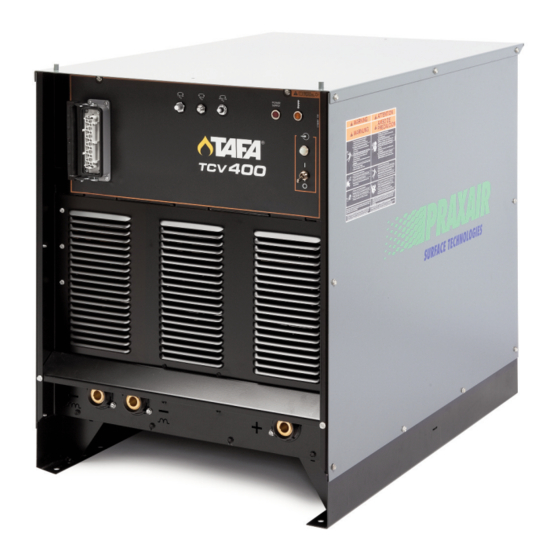
Warning Identification EARTH GROUND CONNECTION Signifying the Earth (Ground) Connection CHASSIS GROUND CONNECTION Signifying the Chassis (Ground) Connection MACHINE DESCRIPTION The TCV400 is an SCR controlled three phase con- stant voltage DC power source. It complies with IEC 60974-1 requirements. TCV400... -
Page 15: Welding Controls
“ I ” is on and “0” is off. Power Supply Enabled (115 VAC) 9. OUTPUT CONNECTIONS Power Supply Enabled (24 VAC) The output terminals are recessed on the case 474A 24 VDC front. The TCV400 provides Tweco connector 474A 24 VDC receptacles. 476A 24 VDC 476A... -
Page 16: Operational Features & Controls
SOLID STATE OUTPUT CONTROL The output of the welder is electronically controlled by SCRʼs instead of mechanical contactors, providing extra long life for highly repetitive welding applications. TCV400... -
Page 17: Power Source Operation
Although the machine is designed for use in rain-sheltered environments, the transformer and choke assembly PARALLELING are dipped in a special corrosion resistant epoxy paint. There are no provisions on the TCV400 to permit par- alleling. TERMINAL STRIP CONNECTIONS METER OPTION Terminal strip TS2 located behind the hinged control panel on the front of the power source supplies 115 Ammeter and Voltmeter Kit 610706 may be installed. -
Page 18: Machine And Circuit Protection
115 volt auxiliary transformer. This in turn energizes the main power transformer. The machine is de-energized when the POWER switch is in the “0” position. The white light next to the POWER switch indicates when the input contactor is energized. TCV400... -
Page 19: Maintenance
Blow out the machine at regular intervals. 3. In extremely dusty locations, dirt may accumulate on the remote control terminal strip. Wipe or blow this terminal strip off at regular intervals. This is particularly important in damp locations. TCV400... -
Page 20: Troubleshooting
CAUTION If for any reason you do not understand the test procedures or are unable to perform the tests/repairs safely, contact your Local TAFA Authorized Field Service Facility for technical troubleshooting assistance before you proceed. TCV400... - Page 21 CAUTION If for any reason you do not understand the test procedures or are unable to perform the tests/repairs safely, contact your Local TAFA Authorized Field Service Facility for technical troubleshooting assistance before you proceed. TCV400...
- Page 22 4. Check and replace if defective. CAUTION If for any reason you do not understand the test procedures or are unable to perform the tests/repairs safely, contact your Local TAFA Authorized Field Service Facility for technical troubleshooting assistance before you proceed. TCV400...
- Page 23 CAUTION If for any reason you do not understand the test procedures or are unable to perform the tests/repairs safely, contact your Local TAFA Authorized Field Service Facility for technical troubleshooting assistance before you proceed. TCV400...
- Page 24 In case of an SCR malfunction or failure, the Snubber PC Board should be checked. Turn the machine off and remove the sides of the machine. Board is mount- ed on back of the Front Panel. 1. Visually inspect the Board for overheated compo- nents or damaged components. TCV400...
- Page 25 204 before replacing SCR. FIGURE E.1 PLUG TO SNUBBER BOARD ANODE To (+) side of capacitor bank CATHODE ANODE SCR1 SCR2 SCR3 GATE CATHODE SHUNT Gate leads plug to Control P.C. board To plug To T1 main transformer TCV400...
- Page 26 DIAGRAMS ENHANCED DIAGRAM TCV400...
- Page 27 DIAGRAMS TCV400...
- Page 28 DIAGRAMS FILTER CIRCUIT SCHEMATIC #215B CAP TVS #225B EPIC TCV400...
- Page 29 Do not touch electrically live parts or Keep flammable materials away. Wear eye, ear and body protection. • • • WARNING electrode with skin or wet clothing. Insulate yourself from work and • ground. Spanish No toque las partes o los electrodos Mantenga el material combustible Protéjase los ojos, los oídos y el •...
- Page 30 Keep your head out of fumes. Turn power off before servicing. Do not operate with panel open or • • • WARNING Use ventilation or exhaust to guards off. • remove fumes from breathing zone. Spanish Los humos fuera de la zona de res- •...
Need help?
Do you have a question about the TCV400 and is the answer not in the manual?
Questions and answers