Table of Contents
Advertisement
Quick Links
Advertisement
Table of Contents
Troubleshooting

Related Manuals for Ventrac 4500Y


Summary of Contents for Ventrac 4500Y
- Page 1 ’ peratOr anual 4500Y entrac Original Operator’s Manual 09.10102 Rev. 00...
-
Page 2: To The Owner
To the Owner Contact Information and Product Identification If you need to contact an authorized Ventrac dealer for information on servicing your product, always provide the product model and serial numbers. Please fill in the following information for future reference. See the picture(s) below to find the location of the identification numbers. -
Page 3: Table Of Contents
TABLE OF CONTENTS INTRODUCTION PAGE 7 Product Description ..........................8 Why Do I Need an Operator’s Manual? ....................8 Using Your Manual ..........................9 Manual Glossary ............................9 Safety Decals ............................10 SAFETY PAGE 13 General Safety Procedures ........................14 Training Required ..........................14 Personal Protective Equipment Requirements ..................14 Operation Safety ..........................14 Preventing Accidents ..........................15 Keep Riders Off ............................15... - Page 4 TABLE OF CONTENTS OPERATIONAL CONTROLS (Continued) Fuel Shut-off Valve (V) .........................28 Circuit Breaker & Battery Disconnect (W) ....................28 Seat Prop Plate (X) ..........................28 Seat Latch Strap (Y) ..........................28 Work Light Switch (AA) ........................28 Strobe Light Switch (BB) ........................28 Slope Indicator Gauge (CC) .........................28 Slope Warning Light (DD) ........................28 Directional Signal Switch (EE) ......................28 Hazard Flasher Switch (FF) .........................28...
- Page 5 TABLE OF CONTENTS SERVICE PAGE 38 Service And General Maintenance .......................38 Cleaning And Appearance Care ......................38 Service Access Points ..........................39 Lubrication Locations ...........................39 Checking Hydraulic Oil Level .......................40 Checking Rear Transaxle Oil .......................41 Changing Hydraulic Oil Filters ......................41 Changing Hydraulic Oil ........................42 Changing Rear Transaxle Differential Oil .....................43 Servicing Closed Loop Hydrostatic Drive Circuit ..................43 Servicing Hydraulic Oil Cooler ......................43...
- Page 6 Parking Brake Inspection & Adjustment ....................58 Neutral Adjustment ..........................59 Neutral Switch Adjustment ........................60 Storage ..............................61 Maintenance Schedule .........................62 Maintenance Checklist .........................63 Ventrac Maintenance Log ........................64 TROUBLESHOOTING PAGE 67 Wiring Diagram Reference Key ......................67 Wiring Diagram - Rear Harness ......................68 Wiring Diagram - Front Harness ......................69 Wiring Diagram - Engine Harness ......................70...
-
Page 7: Introduction
Listed below are just some of the items that can provide you versatility as you use your 4500. Please visit our web site, or contact your authorized Ventrac dealer for a complete list of items available for your new power unit. -
Page 8: Product Description
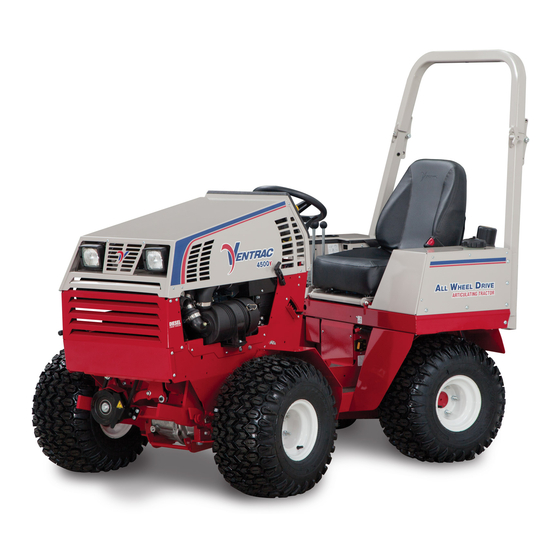
INTRODUCTION Product Description The Ventrac 4500 tractor combines All Wheel Drive and an articulating chassis with a low center of gravity to provide superior traction, braking, stability, and security on tough terrain and slopes without disturbing turf when turning. The attachment is placed out front in a natural view, offering greater precision, as well as maximum protection for the operator. -
Page 9: Using Your Manual
Manual Glossary Power Unit A Ventrac tractor or other Ventrac engine powered device that may be operated by itself or with an attachment or accessory. Attachment A piece of Ventrac equipment that requires a Power Unit for operation. -
Page 10: Safety Decals
SAFETY Safety Decals The following safety decals must be maintained on your Ventrac 4500 power unit. Keep all safety decals legible. Remove all grease, dirt, and debris from safety decals and instructional labels. If any decals are faded, illegible, or missing, contact your dealer promptly for replacements. - Page 11 SAFETY SAFETY 1. Cutting/entanglement hazard - Stay away from moving parts. 1. DANGER: Explosion/Fire Hazard 2. Keep away from fire, sparks, and pilot lights when refueling or storing machine and fuel. 3. Smoking is prohibited. 1. WARNING: Rollover! 2. Keep the roll bar in the raised and locked position and the seat belt securely fastened during operation.
- Page 12 SAFETY 1. Cutting/crushing hazard - Stay away from moving parts. 1. Cutting/dismemberment/entanglement hazard - Stay away from moving parts. 1. WARNING: Read operator’s manual 1. WARNING: 20° maximum slope rating when equipped with single wheels. 2. WARNING: 25° maximum slope rating when equipped with 3”...
-
Page 13: Safety
SAFETY SAFETY 1. Danger: Battery acid is caustic and can cause chemical burns. Keep bystanders a safe distance from the battery. 2. Explosion hazard - batteries produce flammable and explosive gases. 3. Do not expose batteries to arcs, sparks, or open flames. Do not use smoking materials near batteries. -
Page 14: General Safety Procedures
SAFETY General Safety Procedures for Ventrac Power Units, Attachments, & Accessories Training Required • The owner of this machine is solely responsible for properly training the operators. • The owner/operator is solely responsible for the operation of this machine and prevention of accidents or injuries occurring to him/her- self, other people, or property. -
Page 15: Preventing Accidents
SAFETY General Safety Procedures for Ventrac Power Units, Attachments, & Accessories Operation Safety (continued) Operation Safety (continued) • If equipped with a high/low range feature, never shift between high and low range while on a slope. Always move the machine to level ground and engage the parking brake before shifting range. -
Page 16: Operating On Slopes
SAFETY General Safety Procedures for Ventrac Power Units, Attachments, & Accessories Operating On Slopes • Slopes can cause loss-of-control and tip-over accidents, which can result in severe injury or death. Be familiar with the emergency parking brake, along with the power unit controls and their functions. -
Page 17: Maintenance
• If the power unit, attachment, or accessory requires repairs or adjustments not instructed in the operator’s manual, the power unit, attachment, or accessory must be taken to an authorized Ventrac dealer for service. • Never perform maintenance on the power unit and/or attachment if someone is sitting in the operator’s seat. -
Page 18: Hydraulic Safety
SAFETY General Safety Procedures for Ventrac Power Units, Attachments, & Accessories Fuel Safety (continued) • Do not overfill fuel tank. Only fill to bottom of fuel neck, do not fill fuel neck full. Overfilling of fuel tank could result in engine flooding, fuel leakage from the tank, and damage to the emissions control system. -
Page 19: Roll Over Protective Structure (Rops)
SAFETY 4500 Safety Procedures • Power unit hydraulic system may contain stored energy. Before performing maintenance or repairs on the auxiliary hydraulic circuit, remove attachments, engage the park brake, disengage weight transfer system (if equipped), shut off engine, and remove the ignition key. •... -
Page 20: Operator Safety Interlock System
SAFETY 4500 Safety Procedures California Proposition 65 WARNING WARNING The engine exhaust and some of its constituents Battery posts, terminals, and related accessories contain chemicals known to the State of California contain lead and lead compounds which are to cause cancer and birth defects or other known to the State of California to cause cancer reproductive harm. - Page 21 SAFETY 4500 Safety Procedures Testing the Safety Interlock System WARNING CAUTION Never operate the power unit if the safety interlock The daily inspection should be performed prior to system is malfunctioning. Do not disengage or bypass initial startup for the day. any switch.
-
Page 22: Operational Controls
OPERATIONAL CONTROLS OPERATIONAL CONTROLS Standard Operational Control Locations Use the following images to help identify the locations of operational controls. The letter next to each control can be referenced to the list that follows these images. A. Information Cluster Gauge B. -
Page 23: Optional Operational Control Locations
OPERATIONAL CONTROLS Optional Operational Control Locations Use the following images to help identify the locations of operational controls for optional kits. The letter next to each control can be referenced to the list that fol- lows these images. AA. Work Light Switch BB. -
Page 24: Information Cluster Gauge (A)
OPERATIONAL CONTROLS Information Cluster Gauge (A) The low engine oil pressure warning light acti- vates when the engine oil pressure is below safe levels. The light comes on when the ignition key is switched to the on position and stays illuminated until the engine is started and safe oil pressure develops. -
Page 25: Throttle Lever (E)
Lower the front hitch latch lever to lock the 1. Parking Brake Disengaged push the handle forward. hitch latch over the hitch arm pins on Ventrac 2. Parking Brake Engaged (Set) If the parking brake is 3. Parking Brake Release Button attachments. -
Page 26: Pto Belt Tensioner Rod (M)
OPERATIONAL CONTROLS PTO Belt Tensioner Rod (M) Weight Transfer Traction Control Select Lever (O) The PTO belt tensioner rod applies or releases belt tension The weight transfer system transfers weight from to the attachment drive belt. the attachment to the front wheels of the After placing the attachment power unit. -
Page 27: Sdla Control Lever (P & Q)
OPERATIONAL CONTROLS SDLA Control Lever (P & Q) Steering Wheel (R) Turn the steering wheel to the left (counterclockwise) to turn the power unit to the left. Turn the wheel to the right (clockwise) to turn the power unit to the right. Hydraulic Cooler Fan Switch (S) The hydraulic oil cooler fan switch is normally set to the... -
Page 28: Seat Prop Plate (X)
OPERATIONAL CONTROLS Seat Prop Plate (W) Directional Signal Switch (EE) The seat prop plate secures the seat in the flipped 1. Left Turn Signal forward position while service is performed under 2. Right Turn Signal the seat. To secure, tilt the seat forward, lift up the seat prop, and insert the end into the wide portion of the seat plate slot. -
Page 29: Foot Pedal (Hh)
OPERATIONAL CONTROLS Front Hitch Valve (HH) 3 Point Hitch & Rear Auxiliary Control Handles (JJ, KK & LL) The front hitch valve is used to control the lowering of the front hitch. Turning the knob on the front hitch valve counterclockwise 1. -
Page 30: Volt Rear Switches & 4-Pin Socket (Mm, Nn, & Oo)
PTO switch (e.g. The front and rear 4-pin sockets are designed for HG150 generator), allowing the operator to shut off use with Ventrac original equipment only. the power unit PTO from the attachment. These connectors (4-pin socket) are rated for 20 amp maximum current draw. -
Page 31: General Operation
GENERAL OPERATION Daily Inspection 1. Turn the fuel shut-off valve to the On position. 2. Turn the battery disconnect switch to the On position. 3. Move the throttle lever to just past the half throttle position. Always set the parking brake, shut off power unit engine, remove the ignition key, and ensure 4. -
Page 32: Forward And Reverse
GENERAL OPERATION Forward And Reverse If in the case of an emergency, the power unit cannot be stopped with the SDLA control lever, pull back the Set the neutral assist lever to the desired position. parking brake lever to engage the parking brake. Verify that the intended path is safe and free from obstacles. -
Page 33: Detaching
GENERAL OPERATION Detaching Front Auxiliary Couplers 1. Park the power unit on a level surface and set CAUTION the parking brake. 2. Fully raise the front hitch and attachment and EQUIPMENT DAMAGE! set the weight transfer to 0 (if equipped). Dirt and other debris in hydraulic system can cause 3. -
Page 34: Weight Transfer
GENERAL OPERATION Weight Transfer Turning Radius The weight transfer system transfers weight from The 4500 has three mounting positions for the steering the attachment to the front wheels of the power unit cylinder that determine the power unit’s turning radius. when the front hitch is in float or assists in lifting the attachment. -
Page 35: Roll-Over Protection System
GENERAL OPERATION Roll-Over Protection System 3 Point Hitch (Optional Accessory) Some light and medium duty implements (non-PTO WARNING powered) can be used on the rear of a 3 point hitch equipped power unit. Keep the ROPS locked in the upright position and the seat belt securely fastened during operation. -
Page 36: Directional/Hazard Flasher Operation (Optional Accessory)
3. With the operator sitting on the Maximum angle of operation for the engine in the seat, turn the knob (A) on the 4500Y power unit*. front of the seat clockwise to • Kubota D902: 20° continuous, 30° intermittent^ increase the amount of suspen- Attachments, accessories, and tire configuration sion for a heavier operator. -
Page 37: Operation In Water, Mud, Snow, Or Ice
GENERAL OPERATION Operation in Water, Mud, Snow, or Ice Maintain sufficient fuel in tank to ensure continuous operation. WARNING Cease operation if power unit stability is question- able, or if the operator is uncomfortable or unsure of continuing safely. Operation in water, mud, snow, or ice decreases Attachments can affect the stability of the power unit. -
Page 38: Service
(e.g. salt). Failure to clean the equipment may result in corrosion of (including but not limited to) steel, Ventrac recommends that service be performed aluminum, and electrical components. Equipment that by a qualified technician. If you are unsure how... -
Page 39: Service Access Points
SERVICE Service Access Points Lubrication Locations Throughout the service section, different access Lubrication is required at the following points are referred to. The following list and images locations. Refer to the identify shields and covers that may need to be maintenance schedule removed or opened during service. -
Page 40: Checking Hydraulic Oil Level
SERVICE Lubrication Locations (Cont.) Checking Hydraulic Oil Level Check the hydraulic oil level when the hydraulic Drive Shaft system is cold, prior to operating the power unit. If the hydraulic system is warm, allow one hour for the hydraulic system to cool before checking the oil level. Checking the oil level when the hydraulic system is warm will produce an inaccurate oil level reading. -
Page 41: Checking Rear Transaxle Oil
SERVICE Checking Rear Transaxle Oil filter an additional 3/4 of a turn (may require using a strap type filter wrench). Check the rear transaxle oil level when the oil is 10. Apply a thin film of clean oil to the gasket of the cold, prior to operating the power unit. -
Page 42: Changing Hydraulic Oil
SERVICE Changing Hydraulic Oil hydraulic oil tank until the oil level in the plastic sight tube is within the proper range indicated by 1. Wash the underside of both the front and rear the oil level decal. transaxles thoroughly. 12. Start the power unit and let it run at low idle 2. -
Page 43: Changing Rear Transaxle Differential Oil
Ven- trac closed loop drive circuit filtration procedure must be performed. This procedure requires a 3. Remove the drain special Ventrac remote filtering tool and must be plug (B) from the performed by a Ventrac authorized technician. rear transaxle and... -
Page 44: Checking Engine Oil Level
SERVICE Checking Engine Oil Level Changing Engine Oil And Filter CAUTION Attention Avoid Engine Damage! Contact with engine oil can irritate your skin. Wear Failure to check the oil level regularly could lead to protective gloves when working with engine oil. serious damage to your engine, if the engine is run If you come in contact with engine oil, wash it off with an incorrect oil level. -
Page 45: Changing Air Filter Elements
14. Add oil to the engine. (Refer to Engine Owner’s Manual for proper oil specifications and capacity.) Attention: Engine Oil Recommendation For optimal engine life and performance, use Ventrac Full Synthetic Premium Full Synthetic Engine Oil. ENGINE OIL Part # 15.0037-1 SAE 10W-30 Install the oil fill cap and wipe up any oils spills. -
Page 46: Filling The Fuel Tank
SERVICE Changing The In-line Fuel Filter 9. Install the new air filter element(s). 10. Install the filter cap and fasten both latches. 1. Park the power unit on a level surface. Filling The Fuel Tank 2. Engage the parking brake and shut off the engine. 3. -
Page 47: Checking The Fan (Alternator) Belt
SERVICE Checking The Fan (Alternator) Belt Cleaning Engine Compartment & Engine Clean the engine compartment and engine daily or WARNING prior to each use, to reduce the risk of engine over- heating or ignition of accumulated debris. Avoid Personal Injury! 1. -
Page 48: Servicing The Cooling System
SERVICE Servicing The Cooling System Checking The Cooling System 1. Park the power unit on a level surface. WARNING 2. Engage the parking brake and shut off the engine. 3. Remove the key from the ignition switch and Avoid Personal Injury! allow the engine to cool. -
Page 49: Cleaning The Radiator And Screen
SERVICE Cleaning The Radiator And Screen Flushing The Cooling System 1. Park the power unit on a level surface. 1. Drain the cooling system following the proce- dures in the previous section. 2. Engage the parking brake and shut off the engine. 2. -
Page 50: Servicing The Battery
SERVICE Servicing The Battery Removing The Battery 1. Park the power unit on a level surface. DANGER 2. Engage the parking brake and shut off the engine. 3. Remove the key from the ignition switch. The battery produces a flammable and explosive 4. -
Page 51: Cleaning The Battery And Terminals
SERVICE Cleaning The Battery And Terminals Jump Starting Procedure 1. Park the power unit on a level surface. DANGER 2. Engage the parking brake and shut off the engine. 3. Remove the key from the ignition switch. The battery produces a flammable and explosive 4. -
Page 52: Tcm (Tractor Control Module) Explanation
SERVICE booster battery’s negative (-) terminal (3). 8. Insert a new fuse into the socket. Be certain to use the correct amperage fuse or damage may 8. Connect the other end of the negative (-) booster occur to the power unit. cable to the disabled power unit’s ground stud (4). -
Page 53: Replacing Fuses (Rear Fuse Panel)
SERVICE Replacing Fuses (Rear Fuse Panel) Replacing Fuses (Engine) 1. Park the power unit on a level surface. 1. Park the power unit on a level surface. 2. Engage the parking brake and shut off the engine. 2. Engage the parking brake and shut off the engine. 3. -
Page 54: Replacing Light Bulbs (Headlights & Work Lights)
SERVICE Replacing Light Bulbs Replacing The Taillights (Headlights & Work Lights) The taillights are equipped with LEDs and do not use a replaceable bulb. If a taillight no longer func- CAUTION tions, the entire taillight must be replaced. Replacing The Turn Signal Lights The light bulb contains gases under pressure. -
Page 55: Pto Belt Inspection
SERVICE PTO Belt Inspection PTO Belt Tension Adjustment 1. Park the power unit on a level surface. 2. Engage the parking brake and shut off the engine. 3. Remove the key from the ignition switch. Always set the parking brake, shut off power 4. -
Page 56: Clutch Air Gap Inspection & Adjustment
SERVICE 7. Pull the PTO belt tensioner rod out to release 2. Place a .020” (.5 mm) feeler gauge in the slot the belt tension. between the armature and the rotor. 8. Remove the belt tension rod from the belt tension rocker. -
Page 57: Outer Dual Wheel Removal & Installation
SERVICE 5. Lift up the corner of the power unit and secure the left front corner of the foot platform. Torque with a jack stand. to 150 ft-lbs (203 Nm). 6. Remove the lug nuts and lift the wheel off the Outer Dual Wheel Installation: mounting studs. -
Page 58: Rops And Seat Belt Inspection
SERVICE ROPS And Seat Belt Inspection Parking Brake Inspection & Adjustment The parking brake tension must be set to require a WARNING minimum of 15 pounds (7 kg) of force to engage the brake lever 7 clicks or less from the off position. If Failure to inspect and maintain the Roll-Over Pro- less than 15 lbs (7 kg) of force is required to engage tection System and seat belt can lead to serious... -
Page 59: Neutral Adjustment
.03” (.8 mm) with the SDLA lever in the full forward position, the parking brake band may need further service. Contact your authorized Ventrac dealer for assistance. Neutral Adjustment 11. Loosen the acorn nut (A) slightly. NOTE: it is... -
Page 60: Neutral Switch Adjustment
TCM) rized Ventrac dealer for assistance. will be used as an indicator for when the neutral switch is on or off. -
Page 61: Storage
SERVICE Storage Long Term Storage (4 Months or Longer) 1. Change the engine oil to prevent damage that can Preparing the Power Unit for Storage be caused by acidic build up in used motor oil. 1. Clean the power unit. 2. -
Page 62: Maintenance Schedule
Torque to 150 ft-lbs (203 Nm) * If heavy load, high temperature, or dusty condition service intervals are not specified, Ventrac recommends servicing more frequently at 1/2 the standard service interval. ** Operation in severe conditions may require more frequent service intervals. -
Page 63: Maintenance Checklist
Torque to 150 ft-lbs (203 Nm) * If heavy load, high temperature, or dusty condition service intervals are not specified, Ventrac recommends servicing more frequently at 1/2 the standard service interval. ** Operation in severe conditions may require more frequent service intervals. -
Page 64: Ventrac Maintenance Log
SERVICE Ventrac Maintenance Log Model Number:___________________ Serial Number: ͞ Date: Hours: Description of Repairs/Service Initials Service - 64... - Page 65 SERVICE Ventrac Maintenance Log Date: Hours: Description of Repairs/Service Initials Service - 65...
- Page 66 Blank Page...
-
Page 67: Troubleshooting
Wire Reference Key TROUBLESHOOTING Wiring Diagram Reference Key Harness Section Identifier = *Black Wire A = 32.0108 - Harness, Rear = White Wire B = 32.0109 - Harness, Dash = Ground C = 32.0110 - Harness, Front D = 32.0107 - Harness, B&S Engine = Splice or Connection E = 32.0105 - Harness, Kawasaki Engine F = 32.0104 - Harness, Kubota Gas... -
Page 68: Wiring Diagram - Rear Harness
TROUBLESHOOTING Wiring Diagram - Rear Harness Fuel Sender A-028 A-063 A-063 A-061 A-061 Battery Relay Control Module S-267 S-268 A-062 A-062 S-269 A-061 A-061 S-270 Ground Ground A-066 A-066 Stud #1 Stud #1 Battery Disconnect A-065 A-065 A-017 A-030 A-014 A-013 A-267 A-267... -
Page 69: Wiring Diagram - Front Harness
TROUBLESHOOTING Wiring Diagram - Front Harness Q-097 Q-101 B-123 Left B C D Headlight Q-071 AA A Q-073 B-175 Q-075 15 AMP B-104 Q-077 Q-081 B-126 B-127 B-125 B-124 B-154 - B-161 B-122 B-110 Q-100 Fuel Pump B-031 Q-278 B-153 B-176 1 2 3 4 5 6 7 8 9 10... -
Page 70: Wiring Diagram - Engine Harness
TROUBLESHOOTING Wiring Diagram - Engine Harness Start Trigger D-136 Engine Kill (-) D-130 B&S AC Engine Run (+) D-131 D-150 Oil Pressure Light D-174 Ground Starter Serial # 4500P-_ _02860 E-285 Diagnostic Light E-286 E-136 Start Trigger Engine Run (+) E-259 KYS+ E-260... -
Page 71: Wiring Diagram - Optional 30.0219 4-Pin Female Socket & 30.0218 4-Pin Male Plug
Negative (Constant) tion Order Qty. Material Description Material Part # Machine Special Notes Admin ty determines allowable continuous draw *This drawing is for Ventrac equipment only. Positive/Negative 2/26/2014 Date: TOLERANCES: Not Specified* Positive (On/Off Switched) UNLESS OTHERWISE SPECIFIED Green or Brown... -
Page 72: Electrical Troubleshooting Using The Tractor Control Module (Tcm)
TROUBLESHOOTING Electrical Troubleshooting Using The Input Circuits Tractor Control Module (TCM) Brake Switch (A) The light indicates the circuit is closed and the The TCM monitors the electronic circuits necessary for parking brake is engaged. In order for this light to the engine, starter, and PTO to function. - Page 73 Engine Stop Ground (N) Not applicable. Diesel Pre-Heat (O) This output is specific for the diesel engine on the 4500Y. It controls the signal that activates and deac- tivates the glow plugs. Troubleshooting - 73...
-
Page 74: Electrical Troubleshooting Guide
TROUBLESHOOTING Electrical Troubleshooting Guide 1. Always ensure that there is power supplied to the computer (TCM). With the key switch in the Off posi- tion, check to ensure the LED light for the Power input (J) is turned on. If the light is not on: a. -
Page 75: Engine
TROUBLESHOOTING Engine Symptom: Possible Cause: Starter will not engage. Battery disconnect switch in Off position. Tractor Control Module (TCM) is in ‘Sleep’ mode. Blown fuse in power relay module. Blown fuse in start circuit. Parking brake is not engaged. Parking brake switch is out of adjustment. Power unit not in neutral. -
Page 76: Electrical
TROUBLESHOOTING Engine (Continued) Symptom: Possible Cause: Oil light comes on when running. Low oil level. Faulty oil sender. Faulty or plugged oil pump. Engine emits white smoke. Low engine temperature. Faulty head gasket. Water in combustion chamber. Excessive fuel consumption. Plugged or restricted air filters or hose. -
Page 77: Hydraulic
TROUBLESHOOTING Electrical (Continued) Symptom: Possible Cause: PTO does not engage. Blown fuse. Faulty seat switch. (Operator must be in seat). Faulty PTO switch. PTO belt failure. Clutch air gap out of adjustment. Faulty clutch. All TCM lights are on, even with key switch off. Low battery voltage. -
Page 78: Power Unit
TROUBLESHOOTING Power Unit Symptom: Possible Cause: Power unit will not move with engine running. High/low shift lever in the neutral position. Hydraulic oil level is low. Brake not releasing. Pump control arm connecting linkage loose or off. Tow valve bypassing at hydraulic pump. Universal joint at the engine/hydraulic pump is loose. -
Page 79: Specifications
Engine Model ........4500Y Manufacturer ....... . Kubota Model Number. -
Page 80: Dimensions
^Recommended antifreeze: a low silicate, phospate free antifreeze (ethylene glycol) containing supplemental coolant additives (SCA’s) to inhibit corrosion and rust. Attention: Engine Oil Recommendation For optimal engine life and performance, use Ventrac Full Synthetic Premium Full Synthetic Engine Oil. ENGINE OIL Part # 15.0037-1... -
Page 81: Amperage Draw Chart
SPECIFICATIONS Amperage Draw Chart Stockcode Component Description 4500Y Tractor (General Amp Draw) Fuel Pump Lights 37.0060 PTO Clutch 21.0121 Hydraulic Cooler Fan Options 70.4113 Work Light Kit 70.4114 Strobe Light Kit 70.4119 Directional / Hazard Signal Kit 70.4104 12 Volt Front Kit Determined by Attachment 70.4105... -
Page 82: Belt Chart
SPECIFICATIONS Belt Chart Ventrac 4500 Power Unit Belt Size Part Number 4500 PTO Belt B38 belt 81.B038 (Clutch to PTO Idler Pulley) Ventrac Attachment Model Belt Size Part Number EA600 AERA-vator B50 Belt 81.B050 ED200 Edger (with Blower) B45 Belt 81.B045... -
Page 83: Ec Declaration Of Conformity
V.P.I. V.P.I.’s responsibility in respect to claims is limited to making the required repairs or replacements, and no claim of breach of warranty shall be cause for cancellation or rescission of the contract of sale of any Ventrac equipment. -
Page 84: Warranty
(ii) loss, cost, or expense relating to transportation or delivery of turf equipment from the location of owner or location where used by owner to or from any authorized Ventrac dealer; (iii) travel time, overtime, after hours time or other extraordinary repair charges or charge relating to repairs or replace- ments outside of normal business hours at the place of business of an authorized Ventrac dealer;... - Page 85 The California Air Resources Board and Venture Products, Inc. are pleased to explain the evaporative emission control system’s warranty on your 2015-2016 model year Ventrac power unit. In California, new equipment must be designed, built, and equipped to meet the State’s stringent anti-smog standards. Ven- ture Products, Inc.
- Page 86 WARRANTY 3. Any warranted part that is scheduled for replacement as required maintenance in the written instructions supplied is warranted for the period of time before the first scheduled replacement date for that part. If the part fails before the first scheduled replacement, the part will be repaired or replaced by Venture Products, Inc.
Need help?
Do you have a question about the 4500Y and is the answer not in the manual?
Questions and answers