
Related Manuals for Ventrac 4500K


Summary of Contents for Ventrac 4500K
- Page 1 ’ PERATOR ANUAL 4500K ENTRAC 4500P ENTRAC 4500Y ENTRAC 4500Z ENTRAC Revised 02/18/13 09.10081...
- Page 2 To the Owner Contact Information and Product Identifi cation If you need to contact an authorized Ventrac dealer for information on servicing your product, always provide the product model and serial numbers. Please fi ll in the following information for future reference. See the picture(s) below to fi nd the location of the identifi...
-
Page 3: Table Of Contents
TABLE OF CONTENTS INTRODUCTION PAGE 7 Product Description ..........................8 Why Do I Need an Operator’s Manual? ....................8 Using Your Manual ..........................9 Manual Glossary ............................9 Safety Decals ............................10 SAFETY PAGE 13 General Safety Procedures ........................14 Training Required ..........................14 Personal Protective Equipment Requirements ..................14 Operation Safety ..........................14 Preventing Accidents ..........................15 Keep Riders Off ............................15... - Page 4 TABLE OF CONTENTS Hydraulic Cooler Fan Switch (T) ......................27 Seat Slide Lever (U) ..........................27 Fuel Shut-off Valve (V) .........................27 Circuit Breaker & Battery Disconnect (W) ....................27 Seat Prop Plate (X) ..........................27 Seat Latch Strap (Y) ..........................27 Work Light Switch (AA) ........................27 Strobe Light Switch (BB) ........................27 Slope Indicator Gauge (CC) .........................27 Slope Warning Light (DD) ........................27...
- Page 5 TABLE OF CONTENTS SERVICE PAGE 37 Service And General Maintenance .......................37 Cleaning And Appearance Care ......................37 Service Access Points ..........................37 Lubrication Locations ...........................38 Checking Hydraulic Oil Level .......................39 Checking Rear Transaxle Oil .......................39 Changing Hydraulic Oil And Filters ......................39 Servicing Closed Loop Hydrostatic Drive Circuit ..................39 Servicing Hydraulic Oil Cooler ......................39 Checking Engine RPM .........................39 Checking Engine Oil Level ........................40...
- Page 6 ROPS And Seat Belt Inspection ......................55 Parking Brake Inspection & Adjustment ....................55 Neutral Adjustment ..........................56 Neutral Switch Adjustment ........................57 Storage ..............................58 4500K Maintenance Schedule ......................60 4500K Maintenance Checklist ......................61 4500P Maintenance Schedule ......................62 4500P Maintenance Checklist ......................63 4500Z & 4500Y Maintenance Schedule ....................64 4500Z &...
-
Page 7: Introduction
Listed below are just some of the items that can provide you versatility as you use your 4500. Please visit our web site, or contact your authorized Ventrac dealer for a complete list of items available for your new power unit. -
Page 8: Product Description
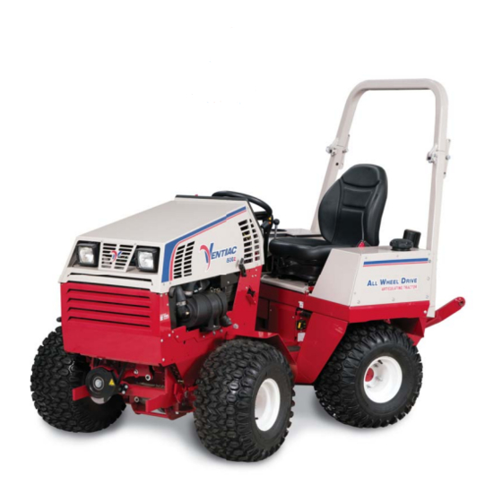
INTRODUCTION Product Description The Ventrac 4500 tractor combines All Wheel Drive and an articulating chassis with a low center of gravity to provide superior traction, braking, stability, and security on tough terrain and slopes without disturbing turf when turning. The attachment is placed out front in natural view, offering greater precision, as well as maximum protection for the operator. -
Page 9: Using Your Manual
It may also be used to alert against unsafe practices. Manual Glossary A Ventrac tractor or other Ventrac engine powered device that may be operated by itself or Power Unit with an attachment or accessory. -
Page 10: Safety Decals
SAFETY Safety Decals The following safety decals must be maintained on your Ventrac 4500 power unit. Keep all safety decals legible. Remove all grease, dirt, and debris from safety decals and instructional labels. If any decals are faded, illegible, or missing, contact your dealer promptly for replacements. - Page 11 SAFETY SAFETY 1. DANGER: Explosion/Fire Hazard 2. Keep away from fi re, sparks, and pilot lights when refueling or storing machine and fuel. 3. Smoking is prohibited. 1. WARNING: Rollover! 2. Keep the roll bar in the raised and locked position and the seat belt securely fastened during operation.
- Page 12 SAFETY 1. Cutting/crushing hazard - Stay away from moving parts. 1. Cutting/entanglement hazard - Stay away from moving parts. 1. Cutting/dismemberment/entanglement hazard - Stay away from moving parts. 1. WARNING: 20° maximum rating when equipped with single wheels. 1. WARNING: Read operator’s manual 2.
-
Page 13: Safety
SAFETY SAFETY 1. Warning: Do not reach over, under, or around guards, 1. Danger: Battery acid is caustic and can cause chemical burns. Keep covers, or shields. Stay away from moving parts. bystanders a safe distance from the battery. 2. Explosion hazard - batteries produce fl ammable and explosive gases. 3. -
Page 14: General Safety Procedures
SAFETY General Safety Procedures for Ventrac Power Units, Attachments, & Accessories Training Required • The owner of this machine is solely responsible for properly training the operators. • The owner/operator is solely responsible for the operation of this machine and prevention of accidents or injuries occurring to him/her- self, other people, or property. -
Page 15: Preventing Accidents
SAFETY General Safety Procedures for Ventrac Power Units, Attachments, & Accessories Operation Safety (continued) • If equipped with a high/low range feature, never shift between high and low range while on a slope. Always move the machine to level ground and engage the parking brake before shifting range. -
Page 16: Operating On Slopes
SAFETY General Safety Procedures for Ventrac Power Units, Attachments, & Accessories Operating On Slopes • Slopes can cause loss-of-control and tip-over accidents, which can result in severe injury or death. Be familiar with the emergency parking brake, along with the power unit controls and their functions. -
Page 17: Maintenance
• If the power unit, attachment, or accessory requires repairs or adjustments not instructed in the opera- tor’s manual, the power unit, attachment, or accessory must be taken to an authorized Ventrac dealer for service. • Never perform maintenance on the power unit and/or attachment if someone is sitting in the operator’s seat. -
Page 18: Hydraulic Safety
SAFETY General Safety Procedures for Ventrac Power Units, Attachments, & Accessories Hydraulic Safety • Make sure all hydraulic connections are tight and all hydraulic hoses and tubes are in good condition. Repair any leaks and replace any damaged or deteriorated hoses or tubes before starting the machine. -
Page 19: Roll Over Protective Structure (Rops)
Your power unit is equipped with a Roll-Over Protective Structure (ROPS). This ROPS was tested in accor- dance with OSHA 1928.51 (ROPS) and ISO 6683 (Seat Belt Anchorage). This ROPS is certifi ed for use on a Ventrac 4500 with a maximum GVW of 4,000 pounds (1818 Kg). •... -
Page 20: Propane Safety (If Applicable)
SAFETY KN4500 Safety Procedures Propane Safety (if applicable) DANGER WARNING Propane is fl ammable and explosive. Use only commercial liquid propane or HD-5 propane. Contact with escaping vapors or liquid may cause Use only liquid withdrawal 33 lb. capacity freezing of tissue or frostbite. aluminum propane tanks. -
Page 21: Operator Safety Interlock System
SAFETY KN4500 Safety Procedures Operator Safety Interlock System The 4500 power unit is equipped with a safety interlock system. This system: • Prevents the engine from starting unless the parking brake is engaged and SDLA control is in neutral. • Prevents the PTO from starting if the operator is not in the seat. -
Page 22: Operational Controls
OPERATIONAL CONTROLS OPERATIONAL CONTROLS Standard Operational Control Locations Use the following images to help identify the locations of operational controls. The letter next to each control can be referenced to the list that follows these images. A. Information Cluster Gauge B. -
Page 23: Optional Operational Control Locations
OPERATIONAL CONTROLS Optional Operational Control Locations Use the following images to help identify the locations of operational controls for optional kits. The letter next to each control can be referenced to the list that fol- lows these images. AA. Work Light Switch BB. -
Page 24: Information Cluster Gauge (A)
OPERATIONAL CONTROLS The low engine oil pressure warning light acti- Information Cluster Gauge (A) vates when the engine oil pressure is below safe levels. The light comes on when the ignition key is switched to the on position and stays illuminated until the engine is started and safe oil pressure develops. -
Page 25: Throttle Lever (E)
Lower the front hitch latch lever to lock the To disengage the parking hitch latch over the hitch arm pins on Ventrac brake, pull back slightly on attachments. Ensure the lever is secured in the brake handle to relieve... -
Page 26: Pto Belt Tensioner Rod (N)
OPERATIONAL CONTROLS PTO Belt Tensioner Rod (N) SDLA Control Lever (Q & R) The PTO belt tensioner rod applies or releases belt tension to the attachment drive belt. After placing the attachment drive belt onto the PTO drive pulley, pushing the PTO belt tensioner rod in (1) until it locks applies tension to the attach- ment drive belt. -
Page 27: Steering Wheel (S)
OPERATIONAL CONTROLS Steering Wheel (S) Seat Prop Plate (X) Turn the steering wheel to the left (counterclockwise) The seat prop plate secures the seat in the fl ipped to turn the power unit to the left. Turn the wheel to the forward position while service is performed under right (clockwise) to turn the power unit to the right. -
Page 28: Directional Signal Switch (Ee)
OPERATIONAL CONTROLS Directional Signal Switch (EE) Front Hitch Valve (II) The front hitch valve 1. Left Turn Signal is used to control the 2. Right Turn Signal lowering of the front hitch. Turning the knob on the front hitch valve Pressing the left portion of the directional signal counterclockwise switch turns on the left turn signal. -
Page 29: Point Hitch & Rear Auxiliary Control Handles (Kk, Ll, & Mm)
OPERATIONAL CONTROLS 3 Point Hitch & Rear Auxiliary Control 12 Volt Rear Switches & 4-Pin Socket Handles (KK, LL, & MM) (OO, PP, & QQ) The rear 4-pin socket provides electrical power to rear mounted attachments that are equipped with electrical controls. (e.g. -
Page 30: General Operation
Always set the parking brake, shut off power unit engine, remove the ignition key, and ensure 4500K Vanguard Gas all moving parts have come to a complete stop before inspecting components, or attempting 1. Pull out the choke handle to the choke or start any repair or adjustment. - Page 31 GENERAL OPERATION 4500Z Kubota Gasoline Or Propane CAUTION Gasoline Use 1. Place the gas/propane selector switch in the Do not run the electric starter continuously for gasoline position. more than 10 seconds. If the engine does not 2. Pull out the choke handle to the choke or start start right away, wait 30 seconds and try again.
-
Page 32: Forward And Reverse
Your hand or foot must 3. Allow the engine to idle for 3-5 minutes. always be ready to brake or stop the power unit. 4. 4500K Vanguard only: move the throttle lever to Power unit movement is con- the fast position. -
Page 33: Detaching
GENERAL OPERATION Detaching Front Auxiliary Couplers 1. Park the power unit on a level surface and set CAUTION the parking brake. 2. Fully raise the front hitch and attachment and EQUIPMENT DAMAGE! set the weight transfer to 0 (if equipped). Dirt and other debris in hydraulic system can cause 3. -
Page 34: High/Low Range
GENERAL OPERATION To set the weight transfer, raise the front hitch to 3. Cab and Versa-loader position: The steering its maximum height and move the weight transfer cylinder must be installed in this position when select lever to the desired position. the cab is installed or when operating the Versa- loader. -
Page 35: Point Hitch (Optional Accessory)
GENERAL OPERATION 3 Point Hitch (Optional Accessory) Directional/Hazard Flasher Operation Some light and medium duty implements (non-PTO (Optional Accessory) powered) can be used on the rear of a 3 point hitch The directional signal / hazard fl asher lights are equipped power unit. -
Page 36: Operating On Slopes
GENERAL OPERATION Maintain suffi cient fuel in tank to ensure continuous Operating On Slopes operation. WARNING Cease operation if power unit stability is question- able, or if the operator is uncomfortable or unsure of continuing safely. AVOID PERSONAL INJURY! Attachments can affect the stability of the power unit. •... -
Page 37: Service
Refer to the specifi c service sections If any component requires replacement, use only for proper cleaning techniques for the engine, radia- original Ventrac replacement parts. tor, and hydraulic oil cooler. Use mild soap and water to clean the power unit. Harsh chemical cleaners Service And General Maintenance could cause damage to the fi... -
Page 38: Lubrication Locations
Spray Lube Steering Cylinder & Connector Link Steering Cylinder & Connector Link On the 4500K, the drive shaft can be greased through access points in the drive shaft cover. On all other models, the front fi tting can be reached in front of the radiator and the rear fi... -
Page 39: Checking Hydraulic Oil Level
Checking the oil level when the hydraulic system is The hydraulic oil and fi lters should be changed warm will produce an inaccurate oil level reading. by an authorized Ventrac dealer only. Refer to the maintenance schedule for service intervals. Attention... -
Page 40: Checking Engine Oil Level
SERVICE Checking Engine Oil Level Kubota Kubota Attention Avoid Engine Damage! Failure to check the oil level regularly could lead to serious damage to your engine, if the engine is run with an incorrect oil level. • Check the engine oil level with the power unit sitting on a level surface and with the engine shut off and the oil cold. -
Page 41: Changing Engine Oil And Filter
SERVICE Changing Engine Oil And Filter 8. Remove the oil fi lter Vanguard Vanguard (B) located on the CAUTION side of the engine. Turn the fi lter counter- clockwise to remove. Contact with engine oil can irritate your skin. Wear 9. -
Page 42: Changing Air Filter Elements
SERVICE Changing Air Filter Elements 9. Install the new air fi lter element(s). 10. Install the fi lter cap and fasten both latches. CAUTION Filling The Fuel Tank When the air fi lter elements are removed, an open- DANGER ing is created to the internal parts of the engine. Be sure nothing falls into the canister that could Fuel is fl... -
Page 43: Changing The Propane Cylinder(S)
SERVICE Changing The Propane Cylinder(s) Pull out on the spring plunger pin DANGER (D) to release the cylinder retainer Propane is fl ammable and/or explosive. Follow all and raise the safety instructions in the Propane Safety section of retainer until the this manual and in the engine operator’s manual. -
Page 44: Changing The In-Line Fuel Filter
SERVICE 2. After the engine has warmed up to operating tem- Checking The Fan (Alternator) Belt perature, check for leaks in the water lines from (Kubota Engines) the vaporizer to the thermostat and the intake. WARNING 3. If any leaks are found, tighten the connections and retest. -
Page 45: Cleaning Engine Compartment & Engine
SERVICE 5. Tighten the alternator adjustment bolt. Servicing The Cooling System 6. Tighten the bottom alternator mounting bolt. WARNING 7. Recheck the belt for proper tension. Cleaning Engine Compartment & Engine Avoid Personal Injury! Clean the engine compartment and engine daily or If the unit has been running, the radiator and radia- prior to each use, to reduce the risk of engine over- tor coolant will be hot and can burn skin! Built-up... -
Page 46: Checking The Cooling System
SERVICE Checking The Cooling System Cleaning The Radiator And Screen 1. Park the power unit on a level surface. 1. Park the power unit on a level surface. 2. Engage the parking brake and shut off the engine. 2. Engage the parking brake and shut off the engine. 3. -
Page 47: Flushing The Cooling System
SERVICE Flushing The Cooling System Servicing The Battery 1. Drain the cooling system following the proce- DANGER dures in the previous section. 2. Close the radiator drain valve, leaving the drain The battery produces a fl ammable and explosive hose in place. gas. -
Page 48: Removing The Battery
SERVICE Removing The Battery Cleaning The Battery And Terminals 1. Park the power unit on a level surface. 1. Park the power unit on a level surface. 2. Engage the parking brake and shut off the engine. 2. Engage the parking brake and shut off the engine. 3. -
Page 49: Jump Starting Procedure
SERVICE Jump Starting Procedure booster battery’s negative (-) terminal (3). 8. Connect the other end of the negative (-) booster DANGER cable to the disabled power unit’s ground stud (4). 9. Start the disabled power unit and remove the The battery produces a fl ammable and explosive booster cables in reverse order of installation gas. -
Page 50: Replacing Fuses (Front Fuse Panel)
SERVICE 8. Insert a new fuse into the socket. Be certain to Replacing Fuses (Rear Fuse Panel) use the correct amperage fuse or damage may 1. Park the power unit on a level surface. occur to the power unit. 2. Engage the parking brake and shut off the engine. 9. -
Page 51: Replacing Fuses (Engine)
SERVICE Replacing Fuses (Engine) Replacing Light Bulbs (Headlights & Work Lights) 1. Park the power unit on a level surface. 2. Engage the parking brake and shut off the engine. CAUTION 3. Remove the key from the ignition switch and allow the engine to cool. -
Page 52: Replacing The Taillights
SERVICE Replacing The Taillights PTO Belt Inspection The taillights are equipped with LEDs and do not use a replaceable bulb. If a taillight no longer func- tions, the entire taillight must be replaced. Always set the parking brake, shut off power Replacing The Turn Signal Lights unit engine, remove the ignition key, and ensure The signal lights used for the turn signal / hazard... -
Page 53: Pto Belt Tension Adjustment
SERVICE PTO Belt Tension Adjustment 8. Remove the belt tension rod from 1. Park the power unit on a level surface. the belt tension 2. Engage the parking brake and shut off the engine. rocker. 3. Remove the key from the ignition switch. 9. -
Page 54: Outer Dual Wheel Removal & Installation
SERVICE jack stand. Lower the power unit to the ground. 5. Tighten the draw bolt and torque to 120 ft-lbs (163 Nm). Repeat for the other three wheels. 4. Tighten the wheel nuts in a crisscross sequence as shown. Torque to 55 ft-lbs (75 Nm). 6. -
Page 55: Rops And Seat Belt Inspection
SERVICE ROPS And Seat Belt Inspection Parking Brake Inspection & Adjustment The parking brake tension must be set to require a WARNING minimum of 15 pounds (7 kg) of force to engage the brake lever 7 clicks or less from the off position. If Failure to inspect and maintain the Roll-Over Pro- less than 15 lbs (7 kg) of force is required to engage tection System and seat belt can lead to serious... -
Page 56: Neutral Adjustment
.03” (.8 mm) with the SDLA lever in the full forward position, the parking brake band may need further service. Contact your authorized Ventrac dealer for assistance. Neutral Adjustment 11. Loosen the acorn nut (A) slightly. NOTE: it is... -
Page 57: Neutral Switch Adjustment
(TCM) The neutral rized Ventrac dealer for assistance. switch input light (A - 2nd light down from the top on the... -
Page 58: Storage
SERVICE Storage Long Term Storage (4 Months or Longer) 1. Change the engine oil to prevent damage that can Preparing the Power Unit for Storage be caused by acidic build up in used motor oil. 1. Clean the power unit. 2. - Page 59 Blank Page...
-
Page 60: 4500K Maintenance Schedule
Torque to 150 ft-lbs * If heavy load, high temperature, or dusty condition service intervals are not specified, Ventrac recommends servicing more frequently at 1/2 the standard service interval. ** Operation in severe conditions may require more frequent service intervals. -
Page 61: 4500K Maintenance Checklist
Torque to 150 ft-lbs * If heavy load, high temperature, or dusty condition service intervals are not specified, Ventrac recommends servicing more frequently at 1/2 the standard service interval. ** Operation in severe conditions may require more frequent service intervals. -
Page 62: 4500P Maintenance Schedule
Torque to 150 ft-lbs * If heavy load, high temperature, or dusty condition service intervals are not specified, Ventrac recommends servicing more frequently at 1/2 the standard service interval. ** Operation in severe conditions may require more frequent service intervals. -
Page 63: 4500P Maintenance Checklist
Torque to 150 ft-lbs * If heavy load, high temperature, or dusty condition service intervals are not specified, Ventrac recommends servicing more frequently at 1/2 the standard service interval. ** Operation in severe conditions may require more frequent service intervals. -
Page 64: 4500Z & 4500Y Maintenance Schedule
Torque to 150 ft-lbs * If heavy load, high temperature, or dusty condition service intervals are not specified, Ventrac recommends servicing more frequently at 1/2 the standard service interval. ** Operation in severe conditions may require more frequent service intervals. -
Page 65: 4500Z & 4500Y Maintenance Checklist
Torque to 150 ft-lbs * If heavy load, high temperature, or dusty condition service intervals are not specified, Ventrac recommends servicing more frequently at 1/2 the standard service interval. ** Operation in severe conditions may require more frequent service intervals. -
Page 66: Troubleshooting
TROUBLESHOOTING in the On position and the forward/reverse control Electrical Troubleshooting Using The (SDLA) must be in the neutral position. Tractor Control Module (TCM) PTO Switch (C) The TCM monitors the electronic circuits necessary for The light indicates the PTO switch is in the On posi- the engine, starter, and PTO to function. - Page 67 Engine Stop Ground (N) The light indicates that power is being sent to the This output is specifi c for the engine on the 4500K. PTO clutch relay. For the PTO output to function, In order for this engine to run, the engine stop ground the operator must be on the seat.
-
Page 68: Electrical Troubleshooting Guide
TROUBLESHOOTING Electrical Troubleshooting Guide 1. Always ensure that there is power supplied to the computer (TCM). With the key switch in the Off position, check to ensure the LED light for the Power input (J) is turned on. If the light is not on: a. -
Page 69: Engine
TROUBLESHOOTING Engine Symptom: Possible Cause: Starter will not engage. Battery disconnect switch in Off position. Blown fuse in power relay module. Blown fuse in start circuit. Parking brake is not engaged. Parking brake switch is out of adjustment. Power unit not in neutral. Neutral switch is out of adjustment. -
Page 70: Electrical
TROUBLESHOOTING Engine (Continued) Symptom: Possible Cause: Engine overheats. Dirty radiator screen. Low coolant level. Debris in engine compartment. Defective radiator cap. Defective thermostat. Loose alternator fan belt. Blown head gasket. Oil light comes on when running. Low oil level. Faulty oil sender. Faulty or plugged oil pump. -
Page 71: Hydraulic
TROUBLESHOOTING Electrical (Continued) Symptom: Possible Cause: Glow plugs do not activate. Blown fuse. Broken wire. Faulty glow plugs. PTO does not engage. Blown fuse. Faulty seat switch. (Operator must be in seat). Park brake switch not set properly (PTO Remote Mode). Faulty PTO switch. -
Page 72: Power Unit
TROUBLESHOOTING Power Unit Symptom: Possible Cause: Power unit will not move with engine running. High/low shift lever in the neutral position. Hydraulic oil level is low. Brake not releasing. Pump control arm connecting linkage loose or off. Tow valve bypassing at hydraulic pump. Universal joint at the engine/hydraulic pump is loose. -
Page 73: Specifications
Headlight ......Halogen (55 watt) Attachment System ......Ventrac Mount ^ Propane, if equipped with optional kit. -
Page 74: Dimensions
Venture Products, Inc. reserves the right to change these specifi cations without notice. * May vary based on tire size, type, and infl ation. ** Weight varies based on engine size, tire options, and optional accessories. Fluid Capacities Ventrac 4500 Fluid Capacities 4500K 4500P 4500Z... -
Page 75: Belt Chart
SPECIFICATIONS Belt Chart Ventrac 4500 Power Unit Belt Size Part Number 4500 PTO Belt B38 belt 81.B038 (Clutch to PTO Idler Pulley) Ventrac Attachment Model Belt Size Part Number B50 Belt 81.B050 EA600 AERA-vator B45 Belt 81.B045 ED200 Edger (with Blower) B46 Belt 81.B046... -
Page 76: Warranty
V.P.I. V.P.I.’s responsibility in respect to claims is limited to making the required repairs or replacements, and no claim of breach of warranty shall be cause for cancellation or rescission of the contract of sale of any Ventrac equipment. - Page 77 (ii) loss, cost, or expense relating to transportation or delivery of turf equipment from the location of owner or location where used by owner to or from any authorized Ventrac dealer; (iii) travel time, overtime, after hours time or other extraordinary repair charges or charge relating to repairs or replace- ments outside of normal business hours at the place of business of an authorized Ventrac dealer;...
Need help?
Do you have a question about the 4500K and is the answer not in the manual?
Questions and answers