
Related Manuals for Ventrac 4500P


Summary of Contents for Ventrac 4500P
- Page 1 Operator’s Manual 4500P Serial Number 4500P-AJ01001 -- VENTRAC.COM Revision 02/01/21 https://www.tractormanualpdf.info/ Original Operator’s Manual 09.10108 Rev. 15...
- Page 2 To the Owner Contact Information and Product Identification If you need to contact an authorized Ventrac dealer for information on servicing your product, al- ways provide the product model and serial numbers. Please fill in the following information for future reference. See the picture(s) below to find the loca- tion of the identification numbers.
-
Page 3: Table Of Contents
TABLE OF CONTENTS INTRODUCTION PAGE 7 Product Description ..........7 Why Do I Need an Operator’s Manual? . - Page 4 TABLE OF CONTENTS OPERATIONAL CONTROLS (Continued) Slope Warning Light (DD) ..........30 Directional Signal Switch (EE) .
- Page 5 TABLE OF CONTENTS SERVICE PAGE 45 Service and General Maintenance ......... 45 Cleaning and Appearance Care .
- Page 6 TABLE OF CONTENTS SERVICE (Continued) Tire Pressure ........... . . 65 ROPS and Seat Belt Inspection .
-
Page 7: Introduction
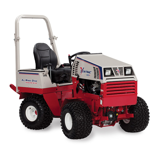
Product Description The Ventrac 4500 tractor combines all wheel drive and an articulating chassis with a low center of gravity to provide superior traction, braking, stability, and security on tough terrain and slopes without disturbing turf when turning. The attachment is placed out in front in a natural view, offering greater precision, as well as maximum protection for the operator. -
Page 8: Using Your Manual
Manual Glossary Power Unit A Ventrac tractor or other Ventrac engine powered device that may be operated by itself or with an attachment or accessory. Attachment A piece of Ventrac equipment that requires a Power Unit for operation. -
Page 9: General Safety Procedures
SAFETY General Safety Procedures for Ventrac Power Units, Attachments, & Accessories Training Required • The owner of this machine is solely responsible for properly training the operators. • The owner/operator is solely responsible for the operation of this machine and for the prevention of ac- cidents or injuries occurring to him/herself, other people, or property. - Page 10 SAFETY General Safety Procedures for Ventrac Power Units, Attachments, & Accessories • Always wear a seat belt if the machine has a roll cage/bar installed and in the upright position. • Ensure the attachment or accessory is locked or fastened securely to the power unit before operating.
-
Page 11: Keep Riders Off
SAFETY General Safety Procedures for Ventrac Power Units, Attachments, & Accessories • To reduce the hazard of fire, keep the battery compartment, engine, and muffler areas free of grass, leaves, excessive grease, and other flammable materials. • Secure long hair and loose clothing. Do not wear jewelry. -
Page 12: Roadway Safety
When new components are installed, be sure that the current safety decals are affixed to the replacement components. • If any component requires replacement, use only original Ventrac replacement parts. • Always turn the battery disconnect to the Off position or disconnect the battery before performing any re- pairs. -
Page 13: Fuel Safety
• If the power unit, attachment, or accessory requires repairs or adjustments not instructed in the operator’s manual, the power unit, attachment, or accessory must be taken to an authorized Ventrac dealer for service. • Never perform maintenance on the power unit and/or attachment if someone is in the operator’s station. -
Page 14: Hydraulic Safety
SAFETY General Safety Procedures for Ventrac Power Units, Attachments, & Accessories • Remove the machine from the truck or trailer and refuel it on the ground. If this is not possible, refuel the machine using a portable container, rather than from a fuel dispenser nozzle. -
Page 15: Roll Over Protective Structure (Rops)
SAFETY 4500 Safety Procedures • The weight transfer spring may contain stored energy. Always disengage the weight transfer system (if equipped) before performing maintenance or repairs on the weight transfer system, the front hitch, or the lift hydraulics. Roll Over Protective Structure (ROPS) WARNING WARNING Keep the ROPS locked in the upright position and... -
Page 16: Operator Safety Interlock System
SAFETY Operator Safety Interlock System The 4500 power unit is equipped with a safety interlock system. This system: • Prevents the engine from starting unless the parking brake is engaged and the SDLA control is in neutral. • Prevents the PTO from starting if the operator is not in the seat. •... - Page 17 SAFETY Testing the Safety Interlock System (continued) Tests 5-9 test the ‘Engine Run’ function. For each test, start the power unit so that the engine is running. As listed for each test, engage or disengage the parking brake*, place the SDLA in neutral or out of neutral^, and sit on the seat or raise your body weight from the seat.
-
Page 18: Safety Decals
SAFETY Safety Decals The following safety decals must be maintained on your attachment. Keep all safety decals legible. Remove all grease, dirt, and debris from safety decals and instructional labels. If any decals are faded, illegible, or missing, contact your dealer promptly for replacements. When new components are installed, be sure that current safety decals are affixed to the replacement compo- nents. - Page 19 SAFETY 1. Cutting/entanglement hazard - Stay away from moving parts. 1. Warning - Explosion/fire hazard. 2. Keep away from fire, sparks, and pilot lights when refueling or storing machine and fuel. 3. Smoking is prohibited. 3. Use unleaded gasoline only with an ethanol con- tent of 10 percent or less.
- Page 20 SAFETY 1. Pinching or crushing hazard - foot. Stay away from moving parts. 1. Severing of fingers or hand - engine fan. Stay away from moving parts. 1. Warning - 20 degree maximum slope rating when equipped with single wheels. 2.
- Page 21 SAFETY 1. Cutting or pinching hazard. Stay away from moving parts. 1. Caustic liquid/chemical burns hazard. 2. Explosion hazard - batteries produce flammable and explosive gases. 3. Do not expose the battery to arcs, sparks, or open flame. Do not smoke near batteries. 4.
-
Page 22: Operational Controls
OPERATIONAL CONTROLS M. PTO Belt Tensioner Rod Operational Control Locations N. High/Low Shift Lever O. Weight Transfer Select Lever Become familiar with all the controls before you start P. Primary SDLA Control Lever the engine and operate the machine. A. Information Cluster Gauge Q. Secondary SDLA Control Lever B. Warning Cluster Gauge R. Steering Wheel C. Warning Alarm (Continuous) S. Hydraulic Cooler Fan Switch D. Ignition Switch T. Seat Slide Lever E. Throttle Lever... -
Page 23: Optional Operational Control Locations
OPERATIONAL CONTROLS MM. Rear Auxiliary Hydraulic Quick Couplers Optional Operational Control Locations NN. Rear 12V Switch (On/Off) OO. Rear 12V Switch (Momentary On/Off/On) Become familiar with the controls for any optional ac- PP. Rear 12V 4-Pin Socket cessories with which your power unit is equipped. AA. Work Light Switch QQ. Front 12V Switch (On/Off) BB. Strobe Light Switch RR. Front 12V Switch (Momentary On/Off/On) CC. Slope Indicator Gauge SS. -
Page 24: Information Cluster Gauge (A)
OPERATIONAL CONTROLS Information Cluster Gauge (A) The engine oil low pressure warning light activates when the engine oil pressure is below safe levels. The light comes on when the ignition key is switched to the On position and stays illuminated until the engine is started and safe oil pressure develops. -
Page 25: Warning Alarm (C)
OPERATIONAL CONTROLS Warning Alarm (C) Power Take Off (PTO) Switch (G) The warning alarm works with the warning cluster Pull the PTO switch up to the On gauge to alert the operator to problems. The warning position (2) to engage the electric alarm sounds a continuous signal whenever a warn- clutch and send power to the front ing is displayed on the warning cluster gauge. -
Page 26: Neutral Assist Lever (I)
OPERATIONAL CONTROLS Neutral Assist Lever (I) Front Hitch Latch Lever (K) Placing the neutral assist lever in the On The front hitch latch lever locks and unlocks position (2) engages the neutral assist the hitch latch. spring to help return the SDLA control lever Raise the front hitch latch lever to the unlock to the neutral position. -
Page 27: High/Low Shift Lever (N)
OPERATIONAL CONTROLS High/Low Shift Lever (N) Weight Transfer Traction Control Select Lever (O) ATTENTION The weight transfer system transfers weight from the attachment to the front wheels of The high/low range shift lever shifts both the front the power unit. Transferring weight from the and rear transaxles simultaneously. -
Page 28: Sdla Control Lever (P & Q)
OPERATIONAL CONTROLS SDLA Control Lever (P & Q) Steering Wheel (R) Turn the steering wheel to the left (counterclockwise) to turn the power unit to the left. Turn the steering wheel to the right (clockwise) to turn the power unit to the right. -
Page 29: Fuel Shut-Off Valve (U)
OPERATIONAL CONTROLS Fuel Shut-off Valve (U) Seat Prop Plate (W) The fuel shut-off valve controls the flow of fuel to the The seat prop plate secures the seat in the flipped power unit engine. Turn the valve forward position while service is performed under the counterclockwise (1) to the stop to seat. -
Page 30: Work Light Switch (Aa)
OPERATIONAL CONTROLS Work Light Switch (AA) Slope Warning Light (DD) Press the top (1) of the work light switch to (70.4112 Only) turn on the work lights. Press the bottom (2) The slope warning light works with the 70.4112 slope of the switch to turn the work lights off. -
Page 31: Front Hitch Valve (Hh)
OPERATIONAL CONTROLS Front Hitch Valve (HH) 3 Point Hitch & Rear Auxiliary Control Handles (JJ, KK, and LL) The front hitch valve is used to control the lowering of the front hitch. Turning the knob on the front hitch valve counterclockwise (1) increases the speed at which the front hitch and attachment can be lowered. -
Page 32: Rear Auxiliary Quick Couplers (Mm)
ATTENTION being used with the 3 point hitch. The 3 point hitch includes two sets of hydraulic quick couplers. The 4-pin socket is designed for use with Ventrac 12 Volt Rear Switches and 4-Pin Socket original equipment only. (NN, OO, and PP) This connector is rated for 20 amp maximum current draw. -
Page 33: Back Up Alarm (Uu)
OPERATIONAL CONTROLS Back Up Alarm (UU) Backrest Angle Lever (YY) The back up alarm emits an intermittent signal when Lift up the backrest angle lever to release the backrest the power unit is operated in reverse to alert nearby catch. Move the backrest to the desired position and persons that the power unit is backing up. -
Page 34: General Operation
GENERAL OPERATION Daily Inspection Starting the Engine WARNING CAUTION Always engage the parking brake, shut off the pow- Use of ether or starting fluids may cause engine er unit engine, remove the ignition key, and ensure damage and/or personal injury. Do not use ether or that all moving parts have come to a complete stop starting fluids to aid in starting the engine. -
Page 35: Forward And Reverse
GENERAL OPERATION Forward and Reverse Stopping the Power Unit Set the neutral assist lever to the desired position. To slow or stop the power unit, move the SDLA control Verify that the intended path is safe and free from lever or optional foot pedal toward the neutral posi- obstacles. -
Page 36: Attaching
GENERAL OPERATION Attaching Operating Attachments 1. Drive the power unit slowly forward into the hitch Read and understand each attachment operator’s arms of the attachment. Align the lift arms of the manual before using the attachment. power unit with the attachment hitch arms by Front Hitch raising or lowering the front hitch and complete the engagement. -
Page 37: Front Auxiliary Couplers
GENERAL OPERATION Front Auxiliary Couplers Weight Transfer CAUTION The weight transfer system transfers weight from the attachment to the front wheels of the power unit when the front hitch is in float or assists in lifting the Dirt and other debris in the hydraulic system can attachment. -
Page 38: High/Low Range
GENERAL OPERATION High/Low Range Turning Radius CAUTION The 4500 power unit has three mounting positions for the steering cylinder that determine the power unit’s turning radius. Never shift range while under load, while moving, or while on a slope. Always ensure the shift lever is se- cured in the lock position at the end of the shift stroke. -
Page 39: Roll-Over Protection System
GENERAL OPERATION Roll-Over Protection System 3 Point Hitch (Optional Accessory) WARNING Some light and medium duty implements (non PTO powered) can be used on the rear of a 3 point hitch equipped power unit. Keep the ROPS locked in the upright position and the seat belt securely fastened during operation. -
Page 40: Directional/Hazard Flasher Operation (Optional Accessory)
Maximum angle of operation for the engine 2. With the operator sitting on the (Kawasaki FD851D) in the 4500P power unit: 30° seat, turn the knob (A) on the front of the seat continuous. clockwise to increase the amount of suspension for a heavier operator. -
Page 41: 70.4140 Slope Gauge Settings And Operation
GENERAL OPERATION Maintain sufficient fuel in the tank to ensure continu- 70.4140 Slope Gauge Settings and Operation ous operation. WARNING Cease operation if the power unit stability is question- able, or if the operator is uncomfortable or unsure of Do not attempt to enter or use the options menu continuing safely. - Page 42 Startup Every time the power unit is started, the slope gauge will When the desired set-point is reached, hold over the display a Ventrac sensor to save the setting. splash screen, fol- Alarm Alarm Menu Screen 3 changes the visual alarm set-point.
- Page 43 GENERAL OPERATION Display Screen 1 is the factory Menu Screen 6 resets the slope default screen and it displays the total gauge back to the factory default slope angle in degrees. settings. The audible alarm will be turned on, and the audible and visual set-points will be restored to 20 de- grees.
-
Page 44: Audible And Visual Alerts (70.4140 Gauge)
GENERAL OPERATION Audible and Visual Alerts (70.4140 Gauge) Operation in Water, Mud, Snow, or Ice WARNING WARNING Never set the slope limit set-points for the audible Operation in water, mud, snow, or ice decreases or visual alerts to a higher value than the power power unit traction and increases the potential for unit configuration can safely handle. -
Page 45: Service
(e.g. salt). Failure to clean the Ventrac recommends that service of the power unit equipment may result in corrosion of (including but be performed by a qualified technician. If you are... -
Page 46: Service Access Points
SERVICE Service Access Points Lubrication Locations Throughout the service chapter, various access points Lubrication is required at the Grease are referred to. The following list and images identify following locations. Refer to shields and covers that may need to be removed or the maintenance schedule for service Silicone based opened during service. -
Page 47: Checking The Hydraulic Oil Level
SERVICE Drive Shaft Checking the Hydraulic Oil Level Check the hydraulic oil level when the hydraulic system is cold, prior to operating the power unit. If the hydraulic system is warm, allow one hour for the hydraulic system to cool before checking the oil level. Checking the oil level when the hydraulic system is warm will produce an inaccurate oil level reading. -
Page 48: Checking The Rear Transaxle Oil
SERVICE Checking the Rear Transaxle Oil Changing the Hydraulic Oil Filters Check the rear transaxle oil level when the oil is cold, 1. If the power unit has been running, allow time for prior to operating the power unit. the hydraulic system to cool. WARNING 1. -
Page 49: Changing The Hydraulic Oil
SERVICE engine speed for a few minutes. Turn the steer- nating the hydraulic oil. Reinstall the plug into the ing wheel to the left and right a couple of times to front transaxle and tighten 1 to 1-1/2 turns past purge any trapped air out of the hydraulic system. -
Page 50: Changing The Rear Transaxle Differential Oil
SERVICE Changing the Rear Transaxle Differential of the oil fill hole. 6. If the transaxle is equipped with a pipe plug, clean the drain plug and apply pipe sealant to the 1. Remove the rear weights from the hitch bar (if threads, making sure to leave the last two threads equipped). -
Page 51: Servicing The Closed Loop Hydrostatic Drive Circuit
The procedure requires • Do not add oil with the engine running. a special Ventrac remote filtering tool and must be 1. If the power unit has been running, allow the en- performed by a Ventrac authorized technician. -
Page 52: Changing The Engine Oil And Filter
If you come in contact with engine oil, wash if off your skin immediately. For optimal engine life and performance, use Ventrac full synthetic engine oil (Part Number 15.0037-1). ATTENTION 14. Install the oil fill cap and wipe up any oil spills. -
Page 53: Changing The Air Filter Elements
SERVICE Changing the Air Filter Elements Filling the Fuel Tank ATTENTION DANGER Fuel is flammable and explosive. Follow all safety When both air filter elements are removed, an open- instructions in the Fuel Safety section and in the ing is created to the internal parts of the engine. Engine Owner’s Manual. -
Page 54: Changing The In-Line Fuel Filter
SERVICE Changing the In-line Fuel Filter Servicing the Cooling System WARNING 1. Turn the fuel shut-off valve to the Off position. 2. Remove the lower rear frame cover. Discharge of hot, pressurized coolant or touching 3. Loosen the hose a hot radiator and surrounding parts can cause clamps and remove severe burns. -
Page 55: Checking The Cooling System
SERVICE Checking the Cooling System Cleaning the Radiator and Screen 1. Park the power unit on a level surface. 1. If the power unit has been running, allow the engine and radiator to cool. 2. If the power unit has been running, allow the engine to cool. -
Page 56: Flushing The Cooling System
SERVICE Flushing the Cooling System Servicing the Battery DANGER 1. Drain the cooling system. 2. Close the radiator drain valve, leaving the drain hose in place. The battery produces a flammable and explosive 3. Add one can of radiator flush to the radiator and fill gas. -
Page 57: Removing The Battery
SERVICE Removing the Battery Cleaning the Battery and Terminals 1. Tilt the seat forward and fasten in place with the 1. Remove the battery from the power unit. seat prop. 2. Wash the battery with a solution of 60 mL (4 table- 2. -
Page 58: Jump Starting Procedure
SERVICE Jump Starting Procedure 6. Connect the other end of the positive (+) booster cable to the positive (+) terminal (2) of the boost- DANGER er battery. 7. Connect the negative (-) booster cable to the The battery produces a flammable and explosive negative (-) terminal (3) of the booster battery. -
Page 59: Tcm (Tractor Control Module) Explanation
SERVICE TCM (Tractor Control Module) Explanation Replacing Fuses (Front Fuse Panel) The tractor control module (A) is a sealed computer- Turn the battery disconnect ized device designed switch to the Off position. to control the elec- 2. Remove the sealed cover (A) tronic safety related from the fuse panel. -
Page 60: Replacing Fuses (Rear Fuse Panel)
SERVICE Replacing Fuses (Rear Fuse Panel) Replacing Fuses (Engine) 1. Turn the battery disconnect 1. If the power unit has been running, allow the engine to cool. switch to the Off position. 2. Tilt the seat forward and 2. Turn the battery disconnect switch to the Off fasten in place with the seat position. -
Page 61: Switching The Speedometer (Mph Or Km/H)
SERVICE Switching the Speedometer (mph or km/h) 5. Install the new light bulb and secure with the wire spring fastener. The wire harness connection for the speedometer is 6. Connect the light bulb wire to the plug. under the right side of the dash above the hydraulic 7. -
Page 62: Replacing The Strobe Light
SERVICE Replacing the Strobe Light PTO Belt Inspection (70.4155 Strobe Light Kit) Inspecting the PTO belt of this power unit can prevent sudden belt failure by finding problems before they The strobe light in the 70.4155 strobe light kit does not cause a belt to break. -
Page 63: Pto Belt Tension Adjustment
SERVICE PTO Belt Tension Adjustment 6. Remove the belt tensioner rod 1. Pull out on the PTO belt tensioner rod to release from the belt tension from the belt tensioner linkage. tension rocker. 2. Loosen the adjustment bolt (A) and rotate the ten- 7. -
Page 64: Clutch Air Gap Inspection And Adjustment
SERVICE Clutch Air Gap Inspection and Adjustment Wheel Removal and Installation The electric clutch is activated by the PTO switch to Wheel Removal: engage or disengage power to belt driven attach- 1. Park the power unit on a level surface. ments. -
Page 65: Outer Dual Wheel Removal And Installation
SERVICE Outer Dual Wheel Removal and Installa- 4. Insert the threaded end of the dual wheel exten- sion into the inner dual wheel hub. Using both tion hands, turn the dual wheel clockwise until the 1. Raise the power unit approximately 5 cm (2 inch- wheel is tight and there are four threads or fewer es) by driving the power unit onto wood planks visible on the outer wheel extension. -
Page 66: Rops And Seat Belt Inspection
SERVICE ROPS and Seat Belt Inspection Parking Brake Inspection and Adjustment WARNING The parking brake tension must be set to require a mini- mum of 7 kg (15 pounds) of force to engage the brake lever seven clicks or less from the off position. If less Failure to inspect and maintain the Roll-Over Protec- than 7 kg (15 pounds) is required to engage the brake tion System and the seat belt can lead to serious... -
Page 67: Neutral Adjustment
NOTE: it is easier to attain the desired setting if the specification, the parking brake band may require neutral adjustment nut is left snug and a rubber further service. Contact an authorized Ventrac mallet or a piece of wood and a hammer are used dealer for assistance. -
Page 68: Neutral Switch Adjustment
6. Locate the tractor con- attain the correct setting, contact on authorized trol module (TCM) under Ventrac dealer for assistance. the power unit’s hood. The neutral switch input light (A) will be used as... -
Page 69: Storage
SERVICE Storage Long Term Storage (four months or longer) 1. Change the engine oil to prevent damage that can Preparing the Power Unit for Storage be caused by acidic buildup in used motor oil. 1. Clean the power unit. 2. Drain all the fuel out of the fuel tank, start the ATTENTION power unit’s engine, and allow to run until the en- gine stops to ensure all the fuel is out of the fuel... - Page 70 SERVICE Removing the Power Unit from Storage 1. Clean the power unit to remove any accumulated dust or debris. 2. Inspect the power unit as instructed in the Daily Inspection section of this manual. 3. Test the power unit to ensure that all the compo- nents and systems are working properly.
-
Page 71: Maintenance Schedule
SERVICE Maintenance Schedule Maintenance Schedule Grease and Lubrication: Refer to the Lubrication Section Front Hitch ü ü ü ü ü ü ü ü ü ü ü ü ü ü ü ü ü ü ü ü ü Lift Cylinder ü ü ü ü ü ü ü ü ü ü ü ü ü ü ü ü ü ü ü ü ü Center Pivot ü... -
Page 72: Maintenance Checklist
SERVICE Maintenance Checklist Maintenance Checklist Grease and Lubrication: Refer to the Lubrication Section Front Hitch Lift Cylinder Center Pivot Steering Cylinder Drive Shaft 3 Point Cylinder (if equipped) 3 Point Hitch Pivot (if equipped) Lower Connector Link Seat Slide Engine Check the Engine Oil Level Change the Engine Oil and Filter Clean or Replace the Spark Plugs... -
Page 73: Maintenance Log
SERVICE Maintenance Log Serial Number: 4500P - ⃞ ⃞ ⃞ ⃞ ⃞ ⃞ ⃞ ⃞ ⃞ ⃞ ⃞ ⃞ ⃞ ⃞ Date: Hours: Description of Repairs/Service Initials Service - 73 https://www.tractormanualpdf.info/... - Page 74 SERVICE Maintenance Log Date: Hours: Description of Repairs/Service Initials Service - 74 https://www.tractormanualpdf.info/...
-
Page 75: Troubleshooting
TROUBLESHOOTING Electrical Troubleshooting Using the Trac- Input Circuits tor Control Module (TCM) Brake Switch (A) The TCM monitors the electronic circuits necessary for The light indicates the circuit is closed and the park- the engine, the starter, and the PTO to function. These ing brake is engaged. - Page 76 TROUBLESHOOTING Power (J) This light is located at the bottom right corner of the TCM. This light indicates that there is full time power to the TCM and is only shut off by the battery dis- connect switch or if the TCM enters the Sleep mode. It keeps the TCM computer energized to eliminate the delay that would otherwise be present when the key is first turned to the run position.
-
Page 77: Electrical Troubleshooting Guide
TROUBLESHOOTING Electrical Troubleshooting Guide 1. Always ensure that there is power supplied to the computer (TCM). With the key turned to the off position, check to ensure the LED light for the power input (J) is turned on. If the light is not on: a. -
Page 78: Engine
TROUBLESHOOTING Engine Symptom: Possible Cause: The starter will not engage. The battery disconnect switch is in the Off position. The Tractor Control Module (TCM) is in Sleep mode. A blown fuse in the power relay module. A blown fuse in the start circuit. The parking brake is not engaged. -
Page 79: Electrical
TROUBLESHOOTING Engine (Continued) Symptom: Possible Cause: The oil light comes on when the engine is run- The oil level is low. ning. A faulty oil sender. A faulty or plugged oil pump. The engine emits white smoke. The engine temperature is low. A faulty head gasket. -
Page 80: Hydraulic
TROUBLESHOOTING Electrical (Continued) Symptom: Possible Cause: The PTO does not engage. A blown fuse. A faulty seat switch (operator must be on seat). A faulty PTO switch. PTO belt failure. The PTO clutch air gap is out of adjustment. A faulty clutch. All the TCM lights are on, even with the key Low battery voltage. - Page 81 TROUBLESHOOTING Power Unit Symptom: Possible Cause: The power unit will not move with the engine The high/low shift lever is in the neutral position. running. The hydraulic oil level is low. The parking brake is not disengaging. The pump control arm connecting linkage is loose or disconnected. The tow valve is bypassing at the hydraulic pump.
-
Page 82: Specifications
Attachment System ........ -
Page 83: Dimensions
Chart = Use API Classification CI or higher. For optimal engine life and performance, use Ventrac full synthetic engine oil (Part Number 15.0037-1). ^Recommended antifreeze: a low silicate, phosphate free antifreeze (ethylene glycol) containing supplemental coolant additives (SCAs) to inhibit corrosion and rust. -
Page 84: Amperage Draw Chart
SPECIFICATIONS Amperage Draw Chart Stock Code Component Description Amperage 4500P Tractor (General Amp Draw) Fuel Pump Lights 37.0060 PTO Clutch 21.0121 Hydraulic Cooler Fan Options 70.4113 Halogen Work Light Kit 70.4133 LED Work Light Kit 70.4114 Strobe Light Kit 70.4155 Strobe Light Kit 0.35... -
Page 85: Belt Chart
SPECIFICATIONS Belt Chart Ventrac 4500 Power Unit Belt Size Part Number 4500 PTO Belt B38 belt 81.B038 (Clutch to PTO Idler Pulley) Ventrac Attachment Model Belt Size Part Number EA600 AeraVator B50 belt 81.B050 ED200/202 Edger (with blower) B45 belt 81.B045... -
Page 86: Warranty
V.P.I.; (f) repair or replacement arising as a result of any operation from Ventrac equipment that has been altered or modified so as to, in the determination of V.P.I., adversely affect the operation, performance or durability of the equipment or that has altered, modified or affected the equipment so as to change the intended use of the product;... - Page 87 (i) damage or defects due to or arising out of repair of the Ventrac equipment by a person or persons other than an authorized Ventrac service dealer or the installation of parts other than genuine Ventrac parts or Ventrac recommended parts.
Need help?
Do you have a question about the 4500P and is the answer not in the manual?
Questions and answers