
Subscribe to Our Youtube Channel
Related Manuals for Ventrac 4520K


Summary of Contents for Ventrac 4520K
- Page 1 Operator’s Manual 4520K Serial Number 4520K-AR01001 -- VENTRAC.COM Revised 05/23/22 https://www.tractormanualpdf.info/ Original Operator’s Manual 09.10184 Rev. 02...
- Page 2 To the Owner Contact Information and Product Identification If you need to contact an authorized Ventrac dealer for information on servicing your product, al- ways provide the product model and serial numbers. Please fill in the following information for future reference. See the picture(s) below to find the loca- tion of the identification numbers.
-
Page 3: Table Of Contents
TABLE OF CONTENTS INTRODUCTION PAGE 7 Product Description ..........7 Why Do I Need an Operator’s Manual? . - Page 4 TABLE OF CONTENTS OPERATIONAL CONTROLS (Continued) Hazard Flasher Switch (DD) ..........29 Horn Switch (EE) .
- Page 5 TABLE OF CONTENTS SERVICE PAGE 43 Service and General Maintenance ......... 43 Cleaning and Appearance Care .
- Page 6 TABLE OF CONTENTS SERVICE (Continued) Maintenance Checklist ..........66 Maintenance Log .
-
Page 7: Introduction
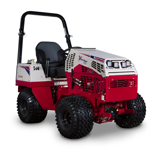
Product Description The Ventrac 4520 tractor combines all wheel drive and an articulating chassis with a low center of gravity to provide superior traction, braking, stability, and security on tough terrain and slopes without disturbing turf when turning. -
Page 8: Using Your Manual
Manual Glossary Power Unit A Ventrac tractor or other Ventrac engine powered device that may be operated by itself or with an attachment or accessory. Attachment A piece of Ventrac equipment that requires a Power Unit for operation. -
Page 9: Safety
SAFETY General Safety Procedures for Ventrac Power Units, Attachments, & Accessories Training Required • The owner of this machine is solely responsible for properly training the operators. • The owner/operator is solely responsible for the operation of this machine and for the prevention of ac- cidents or injuries occurring to him/herself, other people, or property. - Page 10 SAFETY General Safety Procedures for Ventrac Power Units, Attachments, & Accessories • Ensure the attachment or accessory is locked or fastened securely to the power unit before operating. • Ensure that all bystanders are clear of the power unit and the attachment before operating. Stop the ma- chine if someone enters your work area.
-
Page 11: Keep Riders Off
SAFETY General Safety Procedures for Ventrac Power Units, Attachments, & Accessories • Keep people and pets out of the working area. • Know the work area well before operation. Do not operate where traction or stability is questionable. • Reduce speed when you are operating over rough ground. -
Page 12: Roadway Safety
• If the power unit, attachment, or accessory requires repairs or adjustments not instructed in the operator’s manual, the power unit, attachment, or accessory must be taken to an authorized Ventrac dealer for service. • Never perform maintenance on the power unit and/or attachment if someone is in the operator’s station. -
Page 13: Fuel Safety
SAFETY General Safety Procedures for Ventrac Power Units, Attachments, & Accessories • Check the fuel lines for tightness and wear on a regular basis. Tighten or repair them as needed. • To reduce the hazard of fire, keep the battery compartment, engine, and muffler areas free of grass, leaves, and excess grease. -
Page 14: Hydraulic Safety
SAFETY General Safety Procedures for Ventrac Power Units, Attachments, & Accessories • If the fuel tank must be drained, it should be drained outdoors into an approved container. • Check the fuel lines for tightness and wear on a regular basis. Tighten or repair them as needed. -
Page 15: Roll Over Protective Structure (Rops)
SAFETY 4520 Safety Procedures • The weight transfer spring may contain stored energy. Always disengage the weight transfer system (if equipped) before performing maintenance or repairs on the weight transfer system, the front hitch, or the lift hydraulics. Roll Over Protective Structure (ROPS) WARNING WARNING Keep the ROPS locked in the upright position and... -
Page 16: Operator Safety Interlock System
SAFETY Operator Safety Interlock System The 4520 power unit is equipped with a safety interlock system. This system: • Prevents the engine from starting unless the parking brake is engaged and the SDLA control is in neutral. • Prevents the PTO from starting if the operator is not in the seat. •... - Page 17 SAFETY Testing the Safety Interlock System (continued) Tests 5-9 test the ‘Engine Run’ function. For each test, start the power unit so that the engine is running. As listed for each test, engage or disengage the parking brake*, place the SDLA in neutral or out of neutral^, and sit on the seat or raise your body weight from the seat.
-
Page 18: Safety Decals
SAFETY Safety Decals The following safety decals must be maintained on your power unit. Keep all safety decals legible. Remove all grease, dirt, and debris from safety decals and instructional labels. If any decals are faded, illegible, or missing, contact your dealer promptly for replacements. When new components are installed, be sure that current safety decals are affixed to the replacement compo- nents. - Page 19 SAFETY Cutting/entanglement hazard - Stay away from moving parts. Warning - Explosion/fire hazard. Keep away from fire, sparks, and pilot lights when refueling or storing machine and fuel. Smoking is prohibited. Use unleaded gasoline only with an ethanol con- tent of 10 percent or less. Warning - Read operator’s manual.
- Page 20 SAFETY Pinching or crushing hazard - foot. Stay away from moving parts. Caustic liquid/chemical burns hazard. Explosion hazard - batteries produce flammable and explo- sive gases. Do not expose the battery to arcs, sparks, or open flame. Do not smoke near batteries. Keep bystanders away from the battery.
- Page 21 SAFETY Stay away from moving parts. Keep all guards and shields in place. Cutting or pinching hazard. Stay away from mov- ing parts. Decal Description Part Number Quantity ROPS 4500/4520 00.0644 Gasoline Safety 00.0457 Moving Parts 00.0339 4520 Safety 00.0694 Pinching Hazard Foot 00.0639 Battery Hazard...
-
Page 22: Operational Controls
OPERATIONAL CONTROLS Standard Control Locations M. Primary SDLA Control Lever N. Secondary SDLA Control Lever Become familiar with all the controls before you start O. PTO Switch the engine and operate the machine. Headlight Switch A. Information Cluster Gauge Q. USB Receptacle Warning Alarm (Continuous) Seat Slide Lever Ignition Switch... -
Page 23: Optional Accessory Control Locations
OPERATIONAL CONTROLS Optional Accessory Control Locations NN. Slope Indicator Gauge OO. Foot Pedal Become familiar with all the controls before you start 3 Point Hitch Control Lever the engine and operate the machine. QQ. Left Rear Auxiliary Hydraulics Handle AA. Work Light Switch RR. -
Page 24: Information Cluster Gauge (A)
OPERATIONAL CONTROLS Information Cluster Gauge (A) The low engine oil pressure light activates and an alarm sounds when the engine oil pressure is below safe levels. The light comes on when the ignition key 10 11 12 13 is switched to the On position and stays illuminated until the engine is started and safe oil pressure de- velops. -
Page 25: Warning Alarm (B)
OPERATIONAL CONTROLS Warning Alarm (B) High/Low Shift Lever (E) ATTENTION The warning alarm works with the information clus- ter gauge to alert the operator to problems. When a condition activates a warning light on the gauge, the The high/low range shift lever shifts both the front warning alarm also activates and sounds a continu- and rear transaxles simultaneously. -
Page 26: Steering Wheel (F)
OPERATIONAL CONTROLS Steering Wheel (F) Front Hitch Latch Lever Lock (I) The front hitch latch lever lock prevents the accidental Turn the steering wheel to the left (counterclockwise) release of the front hitch latch lever. To release the to turn the power unit to the left. Turn the steering front hitch latch lever, lift the tab on the front hitch wheel to the right (clockwise) to turn the power unit latch lever lock, then move the front hitch latch lever... -
Page 27: Pto Belt Tensioner Rod (L)
OPERATIONAL CONTROLS PTO Belt Tensioner Rod (L) L - Lift: the lift function of the primary SDLA lever has four positions: Up, Hold, Down, and Float Lock. The PTO belt tensioner rod Hold is the default position and holds the hitch applies or releases belt tension arms from moving up or down. -
Page 28: Fuel Shut-Off Valve (S)
OPERATIONAL CONTROLS Fuel Shut-off Valve (S) Choke Lever (X) The fuel shut-off valve controls the flow of fuel to the Pull the choke handle out to aid in starting a cold en- power unit engine. Turn the valve gine. Push the choke handle in for operation. counterclockwise (1) to the stop to allow fuel to flow to the engine. -
Page 29: Work Light Switch (Aa)
ATTENTION (2) of the switch to turn the work lights off. Strobe Light Switch (BB) The 4-pin socket is designed for use with Ventrac original equipment only. Press the top (1) of the strobe light switch This connector is rated for 20 amp maximum to turn on the strobe light. -
Page 30: Volt Rear Switches And 4-Pin Socket (Kk, Ll, And Mm)
12 Volt Rear Switches and 4-Pin Socket Foot Pedal (OO) (KK, LL, and MM) ATTENTION The 4-pin socket is designed for use with Ventrac original equipment only. This connector is rated for 20 amp maximum current draw. The engine alternator and/or battery The foot pedal works in conjunction with the SDLA capacity determine allowable continuous draw. -
Page 31: Point Hitch & Rear Auxiliary Control Handles (Pp, Qq, And Rr)
OPERATIONAL CONTROLS 3 Point Hitch & Rear Auxiliary Control Rear Auxiliary Control Handles (QQ and Handles (PP, QQ, and RR) 3 Point Hitch Lift Left Auxiliary Hyd. Couplers Left Auxiliary Hyd. Couplers Right Auxiliary Hyd. Couplers Float (if equipped) Direction #1 Direction #1 3 Point Hitch Hold Right Auxiliary Hyd. -
Page 32: Seat Slide Lever (Uu)
OPERATIONAL CONTROLS Seat Slide Lever (UU) Optional Armrest Angle Knob (ZZ) Lift up the seat slide lever to release the seat lock. The angle of the optional armrests can be adjusted Move the seat forward or backward to the desired po- individually by rotating the knob on the underside of sition and release the seat slide lever to lock the seat the armrest to raise or lower the front of the armrest. -
Page 33: General Operation
GENERAL OPERATION Daily Inspection Starting the Engine CAUTION WARNING Always engage the parking brake, shut off the pow- Use of ether or starting fluids may cause engine er unit engine, remove the ignition key, and ensure damage and/or personal injury. Do not use ether or that all moving parts have come to a complete stop starting fluids to aid in starting the engine. -
Page 34: Forward And Reverse
GENERAL OPERATION Forward and Reverse Stopping the Power Unit Set the neutral assist lever to the desired position. To slow or stop the power unit, move the SDLA control Verify that the intended path is safe and free from lever or optional foot pedal toward the neutral posi- obstacles. -
Page 35: Attaching
GENERAL OPERATION Attaching the attachment. A side to side movement of the steering wheel may aid in disengagement. 1. Drive the power unit slowly forward into the hitch *Applies only if the attachment is equipped. arms of the attachment. Align the lift arms of the Refer to the attachment manual for additional details. -
Page 36: Front Auxiliary Couplers
GENERAL OPERATION Front Auxiliary Couplers Weight Transfer CAUTION The weight transfer system transfers weight from the attachment to the front wheels of the power unit when the front hitch is in float or assists in lifting the Dirt and other debris in the hydraulic system can attachment. -
Page 37: Turning Radius
GENERAL OPERATION Turning Radius Roll-Over Protection System WARNING The 4520 power unit has three mounting positions for the steering cylinder that determine the power unit’s turning radius. Keep the ROPS locked in the upright position and the seat belt securely fastened during operation. Failure to do so could result in serious injury or loss of life. -
Page 38: Point Hitch (Optional Accessory)
GENERAL OPERATION 3 Point Hitch (Optional Accessory) Directional/Hazard Flasher Operation (Optional Accessory) Some light and medium duty implements (non PTO powered) can be used on the rear of a 3 point hitch The directional signal / hazard flasher lights are equipped power unit. -
Page 39: Operating On Slopes
ATTENTION the attachment operator’s manuals for limitations. Maximum angle of operation for the engine (Vanguard Model 54) in the 4520K power unit: 20° continuous, 30° intermittent^. ^Intermittent: the engine may operate between 20° and 30° for up to 10 minutes. If 10 minutes is reached, the engine must be returned to 20°... -
Page 40: Slope Gauge Settings And Operation
Every time the on slopes that make you feel uncomfortable. power unit is started, SLOPE the slope gauge will Operation display a Ventrac ° splash screen, fol- Alarm Alarm The slope gauge is equipped with a sensor to the left... - Page 41 GENERAL OPERATION Menu Options Display Screen 1 is the factory default screen and it displays the total To calibrate the slope gauge, change audible or visual slope angle in degrees. alert set-points, or to change the display screen, hold your thumb over the slope gauge sensor for eight seconds to enter the options menu.
-
Page 42: Audible And Visual Alerts (70.4140 Gauge)
GENERAL OPERATION Audible and Visual Alerts (70.4140 Gauge) Operation in Water, Mud, Snow, or Ice WARNING WARNING Never set the slope limit set-points for the audible Operation in water, mud, snow, or ice decreases or visual alerts to a higher value than the power power unit traction and increases the potential for unit configuration can safely handle. -
Page 43: Service
(e.g. salt). Failure to clean the Ventrac recommends that service of the power unit equipment may result in corrosion of (including but be performed by a qualified technician. If you are... -
Page 44: Service Access Points
SERVICE Service Access Points Lubrication Locations Throughout the service chapter, various access points Lubrication is required at the Grease are referred to. The following list and images identify following locations. Refer to shields and covers that may need to be removed or the maintenance schedule for service Silicone based opened during service. -
Page 45: Checking The Hydraulic Oil Level
SERVICE Drive Shaft Checking the Hydraulic Oil Level Check the hydraulic oil level when the hydraulic system is cold, prior to operating the power unit. If the hydraulic system is warm, allow one hour for the hydraulic system to cool before checking the oil level. Checking the oil level when the hydraulic system is warm will produce an inaccurate oil level reading. -
Page 46: Checking The Rear Transaxle Oil
SERVICE Checking the Rear Transaxle Oil 8. Place the drain pan under the right rear axle Check the rear transaxle oil level when the oil is cold, beneath the small hydrau- prior to operating the power unit. lic filter (B). 1. -
Page 47: Changing The Hydraulic Oil
SERVICE Changing the Hydraulic Oil engine speed for a few minutes. Turn the steer- ing wheel to the left and right a couple of times to 1. Wash the underside of both the front and rear purge any trapped air out of the hydraulic system. transaxles thoroughly. -
Page 48: Changing The Rear Transaxle Differential Oil
Ventrac closed loop drive circuit filtration pro- cedure must be performed. The procedure requires a special Ventrac remote filtering tool and must be performed by a Ventrac authorized technician. Servicing the Hydraulic Cooler Remove the 1. -
Page 49: Checking The Engine Oil Level
SERVICE Checking the Engine Oil Level Changing the Engine Oil and Filter ATTENTION CAUTION Contact with engine oil can irritate your skin. Wear Failure to check the engine oil regularly could lead protective gloves when working with engine oil. If to serious damage to your engine, if the engine is you come in contact with engine oil, wash if off your run with an incorrect oil level. -
Page 50: Changing The Air Filter Elements
ATTENTION ATTENTION When both air filter elements are removed, an open- For optimal engine life and performance, use Ventrac ing is created to the internal parts of the engine. full synthetic engine oil (Part Number 15.0037-1). Be sure nothing falls into the canister that could make its way into the engine. -
Page 51: Filling The Fuel Tank
SERVICE Filling the Fuel Tank Changing the In-line Fuel Filter DANGER 1. Turn the fuel shut-off valve to the Off position. 2. Remove the lower rear frame cover. Fuel is flammable and explosive. Follow all safety 3. Loosen the hose instructions in the Fuel Safety section and in the clamps and remove Engine Owner’s Manual. -
Page 52: Cleaning The Engine Compartment And Engine
SERVICE Cleaning the Engine Compartment and Servicing the Battery Engine DANGER Clean the engine compartment and the engine daily or prior to each use, to reduce the risk of the engine The battery produces a flammable and explosive overheating or the ignition of accumulated debris. gas. -
Page 53: Removing The Battery
SERVICE Removing the Battery Cleaning the Battery and Terminals 1. Tilt the seat forward and fasten in place with the 1. Remove the battery from the power unit. seat prop. 2. Wash the battery with a solution of 60 mL (4 table- 2. -
Page 54: Jump Starting Procedure
SERVICE Jump Starting Procedure 6. Connect the other end of the positive (+) booster cable to the positive (+) terminal (2) of the boost- DANGER er battery. 7. Connect the negative (-) booster cable to the The battery produces a flammable and explosive negative (-) terminal (3) of the booster battery. -
Page 55: Tcs (Tractor Control System) Explanation
SERVICE TCS (Tractor Control System) Explanation Replacing Fuses (Front Fuse Panel) The tractor control system controls the electronic 1. Turn the battery disconnect switch to the Off safety related functions of this power unit. Both solid position. state and mechanical components are used to ensure 2. -
Page 56: Replacing Fuses (Rear Fuse Panel)
SERVICE Replacing Fuses (Rear Fuse Panel) Replacing the Head Lights 1. Turn the battery disconnect switch to the Off The head lights are equipped with LEDs and do not use position. a replaceable bulb. If a head light no longer functions, the entire work light must be replaced. -
Page 57: Pto Belt Inspection
SERVICE Canopy Strobe Light Synchronization PTO Belt Inspection If a light requires replacement, the strobe lights will Inspecting the PTO belt of this power unit can prevent need to be synchronized after the new light is in- sudden belt failure by finding problems before they stalled and the flash pattern may need to be reset. -
Page 58: Pto Belt Tension Adjustment
SERVICE PTO Belt Tension Adjustment and the front grill and remove from the clutch pulley. 1. Pull out on the PTO belt tensioner rod to release 9. Push the new belt down between the PTO tension tension from the belt tensioner linkage. rocker and the front grill. -
Page 59: Clutch Air Gap Inspection And Adjustment
SERVICE Clutch Air Gap Inspection and Adjustment Wheel Removal and Installation The electric clutch is activated by the PTO switch to Wheel Removal: engage or disengage power to belt driven attach- 1. Park the power unit on a level surface. ments. -
Page 60: Outer Dual Wheel Removal And Installation
SERVICE Outer Dual Wheel Removal and Installa- 4. Insert the threaded end of the dual wheel exten- sion into the inner dual wheel hub. Using both tion hands, turn the dual wheel clockwise until the 1. Raise the power unit approximately 5 cm (2 inch- wheel is tight and there are four threads or fewer es) by driving the power unit onto wood planks visible on the outer wheel extension. -
Page 61: Rops And Seat Belt Inspection
SERVICE ROPS and Seat Belt Inspection Parking Brake Inspection and Adjustment WARNING The parking brake tension must be set to require a mini- mum of 7 kg (15 pounds) of force to engage the brake lever seven clicks or less from the off position. If less Failure to inspect and maintain the Roll-Over Protec- than 7 kg (15 pounds) is required to engage the brake tion System and the seat belt can lead to serious... -
Page 62: Neutral Adjustment
NOTE: it is easier to attain the desired setting if the specification, the parking brake band may require neutral adjustment nut is left snug and a rubber further service. Contact an authorized Ventrac mallet or a piece of wood and a hammer are used dealer for assistance. -
Page 63: Neutral Switch Adjustment
If the neutral switch needs to be checked or adjusted, agents (e.g., salt). Failure to clean the equipment contact an authorized Ventrac dealer. may result in corrosion of (including but not limited to) steel, aluminum, and electrical components. - Page 64 SERVICE Long Term Storage (four months or longer) 1. Change the engine oil to prevent damage that can be caused by acidic buildup in used motor oil. 2. Drain all the fuel out of the fuel tank, start the power unit’s engine, and allow to run until the en- gine stops to ensure all the fuel is out of the fuel lines, carburetor passages, injectors, etc.
-
Page 65: Maintenance Schedule
SERVICE Maintenance Schedule Maintenance Schedule Grease and Lubrication: Refer to the Lubrication Section Front Hitch ü ü ü ü ü ü ü ü ü ü ü ü ü ü ü ü ü ü ü ü ü Lift Cylinder ü ü ü ü ü ü ü ü ü ü ü ü ü ü ü ü ü ü ü ü ü Center Pivot ü... -
Page 66: Maintenance Checklist
SERVICE Maintenance Checklist Maintenance Checklist Grease and Lubrication: Refer to the Lubrication Section Front Hitch Lift Cylinder Center Pivot Steering Cylinder Drive Shaft 3 Point Cylinder (if equipped) 3 Point Hitch Pivot (if equipped) Lower Connector Link Seat Slide Engine Check the Engine Oil Level Change the Engine Oil and Filter Clean or Replace the Spark Plugs... -
Page 67: Maintenance Log
SERVICE Maintenance Log Serial Number: 4520K - Date: Hours: Description of Repairs/Service Initials Service - 67 https://www.tractormanualpdf.info/... - Page 68 SERVICE Maintenance Log Date: Hours: Description of Repairs/Service Initials Service - 68 https://www.tractormanualpdf.info/...
-
Page 69: Troubleshooting
TROUBLESHOOTING Engine Symptom: Possible Cause: The starter will not engage. The battery disconnect switch is in the Off position. A blown fuse in the power relay module. A blown fuse in the start circuit. The parking brake is not engaged. The parking brake switch is out of adjustment. -
Page 70: Electrical
[ Serial # 02232-] Check the 15 amp fuse in position F06 and the 5 amp fuse in position F03. Replace the fuses if necessary. If the electrical issue affects the safety related functions controlled by the TCS, the power unit should be taken to an authorized Ventrac dealer for troubleshooting using diagnostic tools. Symptom: Possible Cause: The battery does not charge. -
Page 71: Hydraulic
TROUBLESHOOTING Electrical (Continued) Symptom: Possible Cause: The PTO does not engage. A blown fuse. A faulty seat switch (operator must be on seat). A faulty PTO switch. PTO belt failure. The PTO clutch air gap is out of adjustment. A faulty clutch. Hydraulic Symptom: Possible Cause:... -
Page 72: Power Unit
TROUBLESHOOTING Power Unit Symptom: Possible Cause: The power unit will not move with the engine The high/low shift lever is in the neutral position. running. The hydraulic oil level is low. The parking brake is not disengaging. The pump control arm connecting linkage is loose or disconnected. The tow valve is bypassing at the hydraulic pump. -
Page 73: Specifications
Attachment System ........ -
Page 74: Dimensions
Grease Lithium Complex NLGI #2 Chart = Use API Classification SH, SJ, or higher. For optimal engine life and performance, use Ventrac full synthetic engine oil (Part Number 15.0037-1). View all manuals Visit ventrac.com/manuals for the latest version of this operator’s manual. -
Page 75: Amperage Draw Chart
SPECIFICATIONS Amperage Draw Chart Stock Code Component Description Amperage 4520K Tractor (General Amp Draw) Fuel Pump Lights 37.0060 PTO Clutch 21.0121 Hydraulic Cooler Fan Options 70.4173 LED Work Light Kit 70.4155 Strobe Light Kit 0.35 70.4156 ECE Directional / Hazard Signal Kit 70.4104... -
Page 76: Belt Chart
SPECIFICATIONS Belt Chart Ventrac 4520 Power Unit Belt Size Part Number 4520 PTO Belt B38 belt 81.B038 (Clutch to PTO Idler Pulley) Ventrac Attachment Model Belt Size Part Number EA600 AeraVator B50 belt 81.B050 ED200/202 Edger (with blower) B45 belt 81.B045... -
Page 77: Warranty
V.P.I.; (f) repair or replacement arising as a result of any operation from Ventrac equipment that has been altered or modified so as to, in the determination of V.P.I., adversely affect the operation, performance or durability of the equipment or that has altered, modified or affected the equipment so as to change the intended use of the product;... - Page 78 (i) damage or defects due to or arising out of repair of the Ventrac equipment by a person or persons other than an authorized Ventrac service dealer or the installation of parts other than genuine Ventrac parts or Ventrac recommended parts.
Need help?
Do you have a question about the 4520K and is the answer not in the manual?
Questions and answers
What is the pivot height off the ground of the hitch point on a Ventrac 4520 tractor. I'm going to attach the EC240 24" sod cutter to a different tractor and I'm thinking the pivot point is critical to maintain so the sod cutter will function properly. I went to Burris Equipment in Waukegan, IL and measured that pivot point to be around 10" but the tractor was sitting on gravel so I'm wondering if 10" is correct or is it a 1/4" or 1/2" higher or lower. Thanks for you help. Dan Cline 1623 N Wilke Road Arlington Heights, IL 847-392-6630