Table of Contents
Advertisement
Quick Links
Advertisement
Table of Contents

Related Manuals for Ventrac LE3200


Summary of Contents for Ventrac LE3200
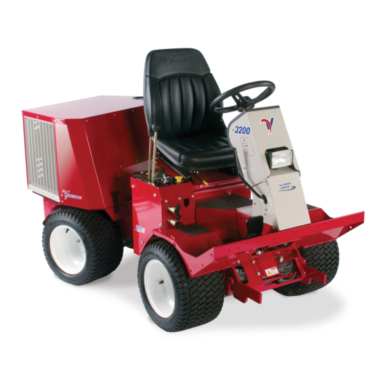
- Page 1 ’ PERATOR ANUAL ENTRAC 3200 Original Operator’s Manual 09.10092 Rev. 00...
-
Page 2: To The Owner
To the Owner Contact Information and Product Identifi cation If you need to contact an authorized Ventrac dealer for information on servicing your product, always provide the product model and serial numbers. Please fi ll in the following information for future reference. See the picture(s) below to fi nd the location of the identifi... -
Page 3: Table Of Contents
Roadway Safety ...........................13 Truck Or Trailer Transport ........................13 Maintenance ............................14 Fuel Safety ............................14 Hydraulic Safety ...........................15 Operator Platform Access ........................15 LE3200 Safety Procedures ........................15 Operator Interlock Systems ........................16 OPERATIONAL CONTROLS PAGE 17 Operational Control Locations ......................17 Ignition Key Switch (J) ..........................18 Steering Tilt Adjustment Lever (I) ......................18... - Page 4 TABLE OF CONTENTS GENERAL OPERATION PAGE 21 Daily Inspection ............................21 Starting the Engine ..........................21 Forward and Reverse ...........................21 Stopping the Power Unit ........................22 Attaching ..............................22 Detaching .............................22 Operating Attachments .........................22 Front Hitch ............................22 Weight Transfer ............................22 PTO Drive Belt .............................23 Front Auxiliary Couplers ........................23 12 Volt Auxiliary Outlets (Optional Equipment) ...........................23...
- Page 5 Controls/Instrumentation ........................46 Other Features .............................46 Dimensions ............................47 Fluid Capacities ............................47 Noise Emissions ...........................48 Vibration Levels ............................48 EC Declaration of Conformity .......................49 WARRANTY PAGE 50 View all manuals A copy of the parts manual and this operator’s manual is available at: http://ventrac.com/manuals...
-
Page 6: Introduction
ONE Tractor Solution. Listed below are just some of the items that can provide you versatility as you use your LE3200. Please visit our web site, or contact your authorized Ventrac dealer for a complete list of items available for your new tractor. -
Page 7: Product Description
Ventrac dealer for a replacement. When using a Ventrac attachment, be sure to read and follow the safety and operating instructions of both the power unit and the attachment being used to ensure the safest operation possible. -
Page 8: Using Your Manual
Manual Glossary Power Unit A Ventrac tractor or other Ventrac engine powered device that may be operated by itself or with an attachment or accessory. Attachment A piece of Ventrac equipment that requires a Power Unit for operation. -
Page 9: Safety
SAFETY Safety Decals The following safety decals must be maintained on your Ventrac 3200 power unit. Keep all safety decals legible. Remove all grease, dirt, and debris from safety decals and instructional labels. If any decals are faded, illegible, or missing, contact your dealer promptly for replacements. - Page 10 SAFETY 1. DANGER: Explosion / fi re hazard. 2. Keep away from fi re, sparks, and pilot lights when refueling or storing machine and fuel. 1. WARNING: Read operator’s manual. 3. Smoking is prohibited. 2. Wear personal protective gear, such as safety glasses, closed toe shoes or boots, and ear protection.
-
Page 11: General Safety Procedures
SAFETY General Safety Procedures for Ventrac Power Units, Attachments, & Accessories Training Required • The owner of this machine is solely responsible for properly training the operators. • The owner/operator is solely responsible for the operation of this machine and prevention of accidents or injuries occurring to him/her- self, other people, or property. -
Page 12: Preventing Accidents
SAFETY General Safety Procedures for Ventrac Power Units, Attachments, & Accessories Operating Safely (continued) • If equipped with a high/low range feature, never shift between high and low range while on a slope. Always move the machine to level ground and place the selector lever in park before shifting range. -
Page 13: Operating On Slopes
SAFETY General Safety Procedures for Ventrac Power Units, Attachments, & Accessories Operating On Slopes • Slopes can cause loss-of-control and tip-over accidents, which can result in severe injury or death. Be familiar with the emergency parking brake, along with the power unit controls and their functions. -
Page 14: Maintenance
• If the power unit, attachment, or accessory requires repairs or adjustments not instructed in the operator’s manual, the power unit, attachment, or accessory must be taken to an authorized Ventrac dealer for service. • Never perform maintenance on the power unit and/or attachment if someone is sitting in the operator’s seat. -
Page 15: Hydraulic Safety
SAFETY General Safety Procedures for Ventrac Power Units, Attachments, & Accessories Hydraulic Safety • Make sure all hydraulic connections are tight and all hydraulic hoses and tubes are in good condition. Repair any leaks and replace any damaged or deteriorated hoses or tubes before starting the machine. -
Page 16: Operator Interlock Systems
ISO 21299 (ROPS) and ISO 3776-2 and ISO 3776-3 (Seat and/or the ROPS structure can reduce safety Belt Anchorage). This ROPS is certifi ed for use on a Ventrac and could cause damage to the machine. Do 3200 with a maximum GVW of 2,200 pounds (1,000 kg). -
Page 17: Operational Controls
OPERATIONAL CONTROLS Operational Control Locations The following images are referenced with letters to help identify the locations of operational controls for this power unit. L - Primary S.D.L.A. Control Lever M - Secondary S.D.L.A. Control Lever N - Tachometer/Hour Meter A - Volt Gauge O - Throttle B - Engine Coolant Temperature Gauge... -
Page 18: Ignition Key Switch (J)
This position makes neutral easy to fi nd and maintain. Signifi es low or no engine oil pressure. It is recommended that this position be used when learning the operation of the Ventrac, loading and Water In Fuel Warning Light (D) unloading, attaching and removing attachments, and Signifi... -
Page 19: Attachment Lock Lever (F)
Unlock Unlock The attachment lock lever engages the hitch lock for attaching or detaching Ventrac attachments. Weight Transfer Adjustment Lever (G) The two couplers are a part of the auxiliary hydrau- lic circuit and are used with an attachment which requires hydraulics (e.g. -
Page 20: Levers (L & M)
OPERATIONAL CONTROLS S.D.L.A. Levers (L & M) (Speed, Direction, Lift, & Auxiliary Control Levers) The S.D.L.A. is the primary control for the power unit and consists of two parts: the primary lever (L) con- trols the Speed, Direction of power unit, and Lift of the power unit hitch arms. -
Page 21: General Operation
GENERAL OPERATION Daily Inspection located under the control dash panel. Allow time for the hydraulic oil to circulate before Always set the parking brake, shut off the tractor the power unit is operated. Severe damage could engine, remove the ignition key, and ensure all result to the hydraulic system if adequate warm moving parts have stopped before checking up is not allowed. -
Page 22: Stopping The Power Unit
GENERAL OPERATION Stopping the Power Unit 10. Restart power unit and slowly back away from the attachment. To slow or stop the power unit, move the S.D.L.A. lever in the opposite direction than you are traveling. Operating Attachments Return the S.D.L.A. lever to the neutral position to Refer to the attachment’s manual for the proper make a complete stop. -
Page 23: Pto Drive Belt
GENERAL OPERATION depends on attachments, ground conditions, and couplers and test the action of the attachment. If the operator preference. A lightweight attachment (e.g. action is not the desired motion, switch the hoses LA162 Power Blower) will not go down with full weight that the couplers are attached to. -
Page 24: Operating On Slopes
GENERAL OPERATION Operating On Slopes 4. Increase the amount of weight being transferred to the power unit from the attachment while operating on slopes. See weight transfer section. 5. A roll over protection device and seat belt are recommended for operation on slopes. Operation on slopes decreases power unit sta- 6. -
Page 25: Service
Attention If any component requires replacement, use only original Ventrac replacement parts. Cleaning and General Maintenance 4. Engine Hood 5. Hydraulic Access Cover For best results, and to maintain the fi nish of the... -
Page 26: Lubrication Locations
SERVICE Lubrication Locations Grease Lubrication is required at the following locations. For Spray service intervals, see the Maintenance Schedule. Lithium Complex Lube When greasing pivot points and bearings, use only NLGI #2 type grease. one pump of grease. Front Lift Cylinder & Front Steering Cylinder Front Lift Cylinder &... -
Page 27: Checking Engine Rpm
SERVICE Checking Engine RPM 6. Install dipstick back into the engine and remove again. Check the engine RPM when the engine is warmed up and not under load. 7. Check oil level. Level should be between the Add (A) and Full (B) marks on the dipstick. Observe Tachometer NOTE: if oil is low, add small amounts of oil to •... -
Page 28: Cleaning Air Intake System
SERVICE 7. Remove drain cap (A) from the oil drain located 19. Check oil after allowing engine to cool for ap- on rear frame, under the engine. proximately 2 minutes. 20. Refer to “Checking Engine Oil Level” for proper procedures on how to check the oil. Cleaning Air Intake System Avoid personal injury! Wear personal eye protection when using com-... -
Page 29: Servicing Air Filter Elements
SERVICE Servicing Air Filter Elements ATTENTION: Avoid Engine Damage! En- gine air fi lter is vital to the operation of this AVOID ENGINE DAMAGE! power unit. Failure to service air cleaner regu- When removing the air fi lter element, an larly can result in severe engine damage. -
Page 30: Checking Coolant Level
SERVICE Servicing Cooling System slightly and continue to turn counterclockwise and remove cap from radiator. Check that the Checking Coolant Level coolant level is up to the bottom of the fi ller neck. 1. Park power unit on a level surface. 9. -
Page 31: Cleaning Radiator And Screen
Read the label 8. Close radiator drain after all coolant has drained on your antifreeze container or consult your from the radiator. local Ventrac dealer to obtain the correct infor- 9. Flush cooling system. mation for your area. Service - 31... -
Page 32: Servicing Fuel Filter
SERVICE Filling the Fuel Tank Servicing Fuel Filter DANGER Fuel is fl ammable and/or explosive. Follow all Avoid personal injury and/or death from safety instructions in the Fuel Safety section of fumes, fi re, or explosion when working on this manual and in the engine operator’s manual. fuel related parts: •... -
Page 33: Adjusting Alternator Belt Tension
SERVICE 5. Open engine hood to access the alternator. Service the Battery Safely 6. Check belt for excessive wear, cracks, or dam- age. 7. Check for proper tension. Apply 20 lbs. (9 Kg) of pressure to the belt between the alternator and water pump. -
Page 34: Cleaning Battery And Terminals
SERVICE Using a Booster Battery Avoid Personal Injury! The battery produces a fl ammable and explosive gas. The battery may explode. • Do not smoke near battery. • Wear eye protection and gloves. • Do not jump start or charge a cold or frozen battery. -
Page 35: Changing The Headlight Bulb
SERVICE Changing the Headlight Bulb Changing the Taillights 1. Park the power unit on a level surface. 2. Shut off engine and engage park brake. Avoid Personal Injury! 3. Remove ignition key from switch. The headlight bulb contains gases under pres- 4. -
Page 36: Fuses
SERVICE Fuses Inspection of Belts Periodically checking the belts on the Ventrac 3200 can prevent sudden failure by fi nding problems before they cause the belt to break. It is recom- mended to inspect all belts every 50 hours of opera- tion, or if a problem is suspected. -
Page 37: Engine Drive Belt Adjustment
SERVICE Typical belt wear may result in the conditions There are fi ve belts that are used on this power unit shown in the previous fi gure. If any of these condi- as shown below. The Engine Drive Belt (E), the Rear tions occur, then the belt will require replacement. -
Page 38: Engine Drive Belt Replacement
SERVICE 7. With bolts loosened, adjust cradle using long bolt in the back left corner of the rear frame. Adjust so that indicator bracket and end of bolt are in line (K). 8. When in the correct position, torque four engine cradle mount bolts to 20 ft-lbs (27 Nm). -
Page 39: Pto Belt Replacement
SERVICE PTO Belt Replacement 7. Release the tension from the PTO belt by un- latching the two extension arms of the torsion 1. Park power unit on a level surface. spring that is a part of the PTO idler pulley as- 2. -
Page 40: Checking Hydraulic Oil Level
Hydraulic oil and fi lter should be changed at in- tervals of 2000 hours. Hydraulic oil and fi lter to be Avoid Personal Injury! changed by an authorized Ventrac dealer only. Spring may be under high tension. Use caution when releasing spring as pinching Tire Pressure may occur. -
Page 41: Maintenance Schedule
Check Front Hitch Pivot Bolts. Torque to 75 ft-lbs * If heavy load, high temperature, or dusty condition service intervals are not specified, Ventrac recommends servicing more frequently at 1/2 the standard service interval. ** Operation in severe conditions may require more frequent service intervals. -
Page 42: Maintenance Checklist
Check Front Hitch Pivot Bolts. Torque to 75 ft-lbs * If heavy load, high temperature, or dusty condition service intervals are not specified, Ventrac recommends servicing more frequently at 1/2 the standard service interval. ** Operation in severe conditions may require more frequent service intervals. -
Page 43: Troubleshooting
TROUBLESHOOTING Engine: SYMPTOM: POSSIBLE CAUSE: Engine will not turn over. Selector lever is not in the park position. PTO switch is engaged. Neutral start switch is out of adjustment. Low voltage battery. Blown fuse in start circuit. Faulty relay in start circuit. Electrical problem in start circuit. -
Page 44: Electrical System
TROUBLESHOOTING Engine (continued): SYMPTOM: POSSIBLE CAUSE: Engine emits white exhaust smoke. Low engine temperature. Allow engine to warm up. Blown head gasket. Engine emits black or gray exhaust Plugged air intake system. smoke. Engine burning oil. Dirty or faulty injectors. Excessive fuel consumption. -
Page 45: Hydraulic System
TROUBLESHOOTING Hydraulic System: SYMPTOM: POSSIBLE CAUSE: Front attachment fails to lift. Low hydraulic oil. Excessive load on hitch. Faulty hydraulic cylinder. Steering locks up. Low hydraulic oil. Faulty steering cylinder. Excessive noise in hydraulic motors. Low hydraulic oil. Cold temperature. Allow power unit to warm up. Power Unit: SYMPTOM: POSSIBLE CAUSE:... -
Page 46: Specifications
SPECIFICATIONS SPECIFICATIONS Engine Manufacture ........Vanguard Model Number . -
Page 47: Dimensions
^Recommended antifreeze: a low silicate, phospate free antifreeze (ethylene glycol) containing supplemental coolant additives (SCA’s) to inhibit corrosion and rust. Attention: Engine Oil Recommendation For optimal engine life and performance, use Ventrac Full Synthetic Premium Full Synthetic ENGINE OIL Engine Oil. Part # 15.0037-1... -
Page 48: Noise Emissions
SPECIFICATIONS Noise Emissions Power Unit 3200 Mower Attachment LM440 LM520 LM600 LK520 Sound Power Level, dB(A) Operator Sound Pressure Level, dB(A) Note 1: Noise emissions determined per EN 836. Note 2: Specifi cations subject to change without notice. Vibration Levels Power Unit 3200 Mower Attachment... -
Page 49: Ec Declaration Of Conformity
328 East Water St. Orrville, OH 44667 - USA Description Multipurpose device with attachment for lawn mowing Ventrac 3200 Power Unit + LM440 Mower Ventrac 3200 Power Unit + LM520 Mower Model Name Ventrac 3200 Power Unit + LM600 Mower Ventrac 3200 Power Unit + LK520 Mower 39.31409 + 39.35104... -
Page 50: Warranty
Ventrac equipment. Proof of purchase may be required by the dealer to substantiate any warranty claim. - Page 51 (i) damage or defects due to or arising out of repair of Ventrac turf equipment by person or persons other than an authorized Ventrac service dealer or the installation of parts other than genuine Ventrac parts or Ventrac recommended parts.
Need help?
Do you have a question about the LE3200 and is the answer not in the manual?
Questions and answers
how to bleed 3200 fuel lines