Table of Contents
Advertisement
Quick Links
Advertisement
Table of Contents

Related Manuals for Ventrac 4100


Summary of Contents for Ventrac 4100
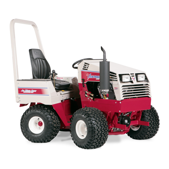
- Page 1 OPERATOR’S MANUAL VENTRAC 4100 Serial # 1502- Revised 06/11/14 09.10050 Rev. 02...
-
Page 2: To The Owner
To the Owner Contact Information and Product Identifi cation If you need to contact an authorized Ventrac dealer for information on servicing your product, always provide the product model and serial numbers. Please fi ll in the following information for future reference. See the picture(s) below to fi nd the location of the identifi... - Page 3 Listed below are just some of the items that can provide you versatility as you use your 4100. Please visit our web site, or contact your authorized Ventrac dealer for a complete list of items available for your new power unit. Item Description...
-
Page 4: Table Of Contents
TABLE OF CONTENTS INTRODUCTION PAGE 7 Product Description ..........................7 Why do I need an Operator’s Manual? ....................7 Using Your Manual ..........................8 Manual Glossary ............................8 SAFETY PAGE 9 Safety Decals ............................9 General Safety Procedures ........................11 Training Required ..........................11 Personal Protective Equipment Requirements ..................11 Operating Safely .......................... - Page 5 TABLE OF CONTENTS GENERAL OPERATION PAGE 23 Daily Inspection ............................23 Starting the Engine ..........................23 Forward and Reverse ...........................23 Stopping the Power Unit ........................24 Detaching .............................24 Operating Attachments .........................24 Front Hitch ............................24 PTO Drive Belt & Pulley ........................24 Front Auxiliary Couplers ........................25 Weight Transfer (Optional Accessory) ....................25 High/Low Range ...........................25 Turning Radius .............................26...
- Page 6 TABLE OF CONTENTS MAINTENANCE CHART PAGE 39 Ventrac 4100 Maintenance Schedule ....................39 Ventrac 4100 Maintenance Checklist ....................40 TROUBLESHOOTING PAGE 41 Engine ..............................41 Electrical ...............................42 Hydraulic ..............................42 Power unit ............................42 SPECIFICATIONS PAGE 43 Electrical ...............................43 Power Train ............................43 Controls & instrument Panel ........................43 Other features ............................43...
-
Page 7: Introduction
• The 4100 is equipped with the quick and effi cient Ventrac Mount System. This allows you to attach over 30 commercial grade attachments in about a minute or less and requires no tools. Why do I need an Operator’s Manual? This manual has been created to help you gain the important knowledge of what is needed to safely oper- ate, maintain, and service your power unit. -
Page 8: Using Your Manual
It may also be used to alert against unsafe practices. Manual Glossary A Ventrac tractor or other Ventrac engine powered device that may be operated by itself or Power Unit with an attachment or accessory. -
Page 9: Safety
SAFETY Safety Decals The following safety decals must be maintained on your Ventrac 4100 power unit. Keep all safety decals legible. Remove all grease, dirt, and debris from safety decals and instructional labels. If any decals are faded, illegible, or missing, contact your dealer promptly for replacements. - Page 10 SAFETY Decal Description Part Number Quantity Danger, Explosion Hazard 00.0121 Warning - Battery Gases 00.0124 Upper Dash - General Safety 00.0175 Lower Dash - High/Low Shift Safety 00.0176 Warning - Moving Parts 00.0216 Warning - Read Owners Manual 00.0217 Warning - Pinching Points 00.0218 Warning - Avoid Injury 00.0219...
-
Page 11: General Safety Procedures
SAFETY General Safety Procedures for Ventrac Power Units, Attachments, & Accessories Training Required • The owner of this machine is solely responsible for properly training the operators. • The owner/operator is solely responsible for the operation of this machine and prevention of accidents or injuries occurring to him/her- self, other people, or property. -
Page 12: Preventing Accidents
SAFETY SAFETY General Safety Procedures for Ventrac Tractors, Attachments, & Accessories Operating Safely (continued) • If equipped with a high/low range feature, never shift between high and low range while on a slope. Always move the machine to level ground and place the selector lever in park before shifting range. -
Page 13: Operating On Slopes
SAFETY General Safety Procedures for Ventrac Tractors, Attachments, & Accessories Operating On Slopes • Slopes can cause loss-of-control and tip-over accidents, which can result in severe injury or death. Be familiar with the emergency parking brake, along with the power unit controls and their functions. -
Page 14: Maintenance
• If the power unit, attachment, or accessory requires repairs or adjustments not instructed in the operator’s manual, the power unit, attachment, or accessory must be taken to an authorized Ventrac dealer for service. • Never perform maintenance on the power unit and/or attachment if someone is sitting in the operator’s seat. -
Page 15: Hydraulic Safety
SAFETY General Safety Procedures for Ventrac Tractors, Attachments, & Accessories Hydraulic Safety • Make sure all hydraulic connections are tight and all hydraulic hoses and tubes are in good condition. Repair any leaks and replace any damaged or deteriorated hoses or tubes before starting the machine. -
Page 16: Roll-Over Protective Structure
SAFETY KT4100 Safety Procedures • Weight transfer springs may contain stored energy. Always disengage the weight transfer system before performing maintenance or repairs on the weight transfer system, the front hitch, or the lift hydraulics. • Power unit hydraulic system may contain stored energy. Before performing maintenance or repairs on the attachment hydraulic system, remove attachments, engage parking brake, disengage weight transfer system, shut off engine, and remove ignition key. -
Page 17: Operator Interlock Systems
SAFETY KT4100 Safety Procedures Operator Interlock Systems The operator interlock systems: • prevent the engine from starting unless the selector lever is in the park position. • prevent the PTO clutch from engaging unless the operator is present on the seat and activates the PTO. •... -
Page 18: Operational Controls
OPERATIONAL CONTROLS OPERATIONAL CONTROLS Under Seat Under Seat Operation - 18... -
Page 19: Operational Control Locations
OPERATIONAL CONTROLS (PTO) S PERATIONAL ONTROL OCATIONS OWER WITCH Depressing the top of the PTO switch engages the The images on the previous page match with ref- electric clutch to provide power to the front attach- erence letters as shown below to help identify the ment. -
Page 20: Light Switch (H)
The front hitch latch handle engages or disengages ELECTOR EVER ARKING RAKE the hitch latch for attaching or detaching Ventrac at- tachments. Raise the handle to open the hitch latch. Position 1: Park/Start Position. In this position, the Lower the handle and ensure the handle is secured park brake is applied, and the in the notch to close the hitch latch. -
Page 21: Foot Pedal (V)
OPERATIONAL CONTROLS improves traction & hillside stability, aids in lifting, 12 V & 4-P UTLET OCKET reduces steering effort, and lessens the attachment Optional accessory. The outlet provides 12 volts of resistance when in contact with the ground. Note: electrical power for a variety of products such as The weight transfer system is only active while the cell phones, radios, spot lights, air compressors, primary S.D.L.A. -
Page 22: Seat Latch (Dd)
OPERATIONAL CONTROLS (DD) ATCH The seat latch (A) secures the standard seat during transport. To release, pull the latch away from the seat plate while lifting up on the seat. (EE) The seat prop (B) secures the seat in the tipped forward position while service is per- formed under the seat. -
Page 23: General Operation
NGINE O RWA R D O RWA R D The 4100 is equipped with an interlock system for your safety. The following procedure is to be fol- lowed to start the power unit: 1. The interlock system requires the “Selector Le- ver”... -
Page 24: Stopping The Power Unit
GENERAL OPERATION GENERAL OPERATION 7. Move the secondary S.D.L.A. lever left and right TOPPING THE OWER to release pressure from the auxiliary hydraulic To slow or stop the power unit, move the S.D.L.A. circuit and disconnect the hydraulic quick cou- control lever in the opposite direction that you are plers from the power unit.* traveling. -
Page 25: Front Auxiliary Couplers
GENERAL OPERATION GENERAL OPERATION RONT UXILIARY OUPLERS Weight Transfer Weight Transfer Chain Lock Chain Lock EQUIPMENT DAMAGE! Dirt and other debris in hydraulic system can cause damage to the system. Wipe clean the mating parts of the couplers before coupling. Use protective rubber plugs over hydraulic couplers when not in use. -
Page 26: Turning Radius
GENERAL OPERATION GENERAL OPERATION handles. The inside handle raises and lowers the URNING ADIUS draw bar. The middle handle controls the left rear set Your power unit has three mounting positions for of hydraulic quick couplers. The outside handle con- the steering cylinder that determine the power unit’s trols the right rear set of hydraulic quick couplers. - Page 27 GENERAL OPERATION OWING OR USHING THE OWER ATTENTION: Avoid damage to your AVOID ENGINE DAMAGE! power unit! Before towing, read and under- Vanguard gasoline engines are rated for a stand the information below. Severe damage maximum angle of operation of 25° for continuous will occur to unit if proper towing procedure use (all directions) and 30°...
-
Page 28: Service
Attention If any component requires replacement, use only original Ventrac replacement parts. & G LEANING ENERAL AINTENANCE For best results, and to maintain the fi nish of the power unit, clean or wash the power unit to remove accumu- lated clippings, leaves, dirt, gravel, and salt deposits. -
Page 29: Lubrication Locations
SERVICE UBRICATION OCATIONS Grease Spray Lube Lubrication is required at the following locations. For service intervals, see Maintenance Schedule. When greasing pivot points and bearings, use only one Lithium Complex NLGI #2 pump of grease. type grease Steering Cylinder & Connector Link (Front) Drive Shaft U-Joint Serial # 1566- Serial # 1502-1565... -
Page 30: Checking Hydraulic Oil Level
(pump, front drive motor, rear drive motor, or any of the three 1/2” hydraulic lines connecting them together) is serviced or replaced, the Ventrac closed loop drive circuit fi ltration procedure must be per- formed. This procedure requires a special Ventrac remote fi... -
Page 31: Checking Engine Rpm
SERVICE HECKING NGINE 7. Check oil level. Level should be Check engine RPM’s when engine is warmed up between the Full (B) and Add (C) on and not under load. the dipstick. Observe Tachometer: 8. NOTE: if oil is low, add small •... -
Page 32: Servicing Air Filter Elements
SERVICE 8. Remove oil fi lter (B) located in front of the left ERVICING ILTER LEMENTS side of the engine. Turn fi lter counterclockwise to remove. AVOID ENGINE DAMAGE! When removing the air fi lter element, an open- ing directly to the internal parts of the engine is created. -
Page 33: Filling The Fuel Tank
SERVICE 10. Install the new fi lter element(s). ERVICING ILTER 11. Reinstall the air canister cap. 12. Close engine hood. ILLING THE AVOID PERSONAL INJURY! Avoid personal injury and/or death from fumes, DANGER fi re or explosion when working on fuel related parts: Fuel is fl... -
Page 34: Cleaning Engine Compartment & Oil Cooler
SERVICE LEANING NGINE OMPARTMENT ERVICING BATTERY & O OOLER Clean engine compartment daily or prior to each use, to reduce the risk of engine overheating and ignition of accumulated debris. 1. Park power unit on a level surface. 2. Engage parking brake and shut off engine. 3. -
Page 35: Cleaning Battery And Terminals
SERVICE 6. Rinse the battery with plain water and dry. 7. Clean terminals and battery cable with wire brush until bright. 8. Apply dielectric grease to terminals to prevent corrosion. SING A OOSTER ATTERY AVOID PERSONAL INJURY! The battery produces a fl ammable and explo- 7. -
Page 36: Changing The Headlight Bulb
SERVICE HANGING THE EADLIGHT HANGING THE AILLIGHTS 1. Park power unit on a level surface. 2. Engage parking brake and shut off engine. AVOID PERSONAL INJURY! 3. Remove ignition key from switch. The headlight bulb contains gases under pres- 4. Remove the tail- sure. -
Page 37: Inspection Of Pto Belt
SERVICE PTO B PTO B NSPECTION OF EPLACEMENT Periodically checking the PTO belt (A) of this power 1. Park power unit on a level surface. unit can prevent sudden failure by fi nding problems 2. Engage parking brake and shut off engine. before they cause the belt to break. -
Page 38: Parking Brake Adjustment
fi rm. If brake is adjusted to tight, it will be diffi cult to engage the selector lever in the park NOTE: If unsure of this procedure or your efforts fail brake position. to remedy the problem, contact your Ventrac dealer. EUTRAL DJUSTMENT ECOMMENDED... -
Page 39: Maintenance Chart
MAINTENANCE CHART 4100 M ENTRAC AINTENANCE CHEDULE This sheet is a guide for recommended Service and Maintenance for the 4100. Service - 39... -
Page 40: Ventrac 4100 Maintenance Checklist
MAINTENANCE CHART 4100 M ENTRAC AINTENANCE HECKLIST This sheet is a checklist for tracking Service and Maintenance for the 4100. Service - 40... -
Page 41: Troubleshooting
TROUBLESHOOTING NGINE YMPTOM OSSIBLE AUSE Starter will not engage. Selector lever is not in the park position. PTO switch is engaged. Neutral start switch is out of adjustment. Dead battery. Blown fuse in start circuit. Faulty relay in start circuit. Electrical problem in start circuit. -
Page 42: Electrical
TROUBLESHOOTING LECTRICAL YMPTOM OSSIBLE AUSE Loose or corroded connections. Battery does not charge. Broken or loose wire in charge system. Defective battery. Defective alternator. Defective voltage regulator. Lights do not activate. Blown fuse. Blown light bulb. Broken wire/connection. Faulty light switch. PTO does not engage. -
Page 43: Specifications
Headlight ......Halogen (55 watt) Attachment System ......Ventrac Mount * May vary based on tire size, type, and infl... -
Page 44: Dimensions
Venture Products, Inc. reserves the right to change these specifi cations without notice. * May vary based on tire size, type, and infl ation. ** Weight varies based on engine size, tire options, and optional accessories. LUID APACITIES Ventrac 4100 Fluid Capacities Engine Oil* 4131 Gas 2.4 qt 2.3L Hydraulic System, Standard Power Unit* 11.4 qt... -
Page 45: Warranty
Ventrac equipment. Proof of purchase may be required by the dealer to substantiate any warranty claim. - Page 46 (i) damage or defects due to or arising out of repair of Ventrac turf equipment by person or persons other than an authorized Ventrac service dealer or the installation of parts other than genuine Ventrac parts or Ventrac recommended parts.
Need help?
Do you have a question about the 4100 and is the answer not in the manual?
Questions and answers