
Subscribe to Our Youtube Channel
Related Manuals for Ventrac 3400L


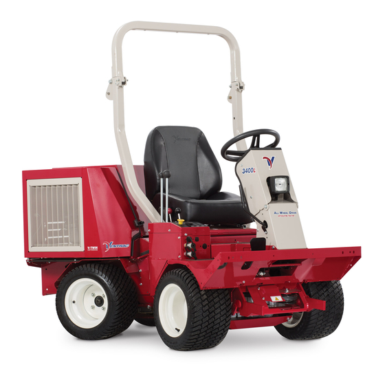
Summary of Contents for Ventrac 3400L
- Page 1 Operator’s Manual 3400L Serial Number 3400L-AK01001 -- VENTRAC.COM Revised 08/07/20 Original Operator’s Manual 09.10086 Rev. 09...
- Page 2 To the Owner Contact Information and Product Identification If you need to contact an authorized Ventrac dealer for information on servicing your product, always provide the product model and serial numbers. Please fill in the following information for future reference. See the picture(s) below to find the location of the identification numbers.
-
Page 3: Table Of Contents
TABLE OF CONTENTS INTRODUCTION PAGE 7 Product Description ..........................8 Why Do I Need an Operator’s Manual? ....................8 Using Your Manual ..........................9 Manual Glossary ............................9 SAFETY PAGE 10 Safety Decals ............................10 General Safety Procedures ........................13 Training Required ..........................13 Requirements for Personal Protective Equipment (PPE) ..............13 Operation Safety ..........................13 Preventing Accidents ..........................14 Keep Riders Off ............................14... - Page 4 TABLE OF CONTENTS OPERATIONAL CONTROLS (Continued) Transmission Neutral Levers (T) ......................25 Horn Switch (AA) ..........................25 Directional Signal Switch (BB) ......................25 Hazard Flasher Switch (CC) ........................25 Work Light Switch (DD) ........................25 Strobe Light Switch (EE) ........................25 12 Volt Rear Switches & 4-Pin Socket (FF, GG, & HH) ................26 12 Volt Front Switches &...
- Page 5 Clutch Air Gap Inspection & Adjustment ....................48 Wheel Removal & Installation ......................48 Tire Pressure ............................48 ROPS And Seat Belt Inspection ......................49 Parking Brake Inspection & Adjustment ....................49 Neutral Adjustment ..........................50 Storage ..............................50 Maintenance Schedule .........................52 Maintenance Checklist .........................53 Ventrac Maintenance Log ........................54...
- Page 6 TABLE OF CONTENTS TROUBLESHOOTING PAGE 57 Wiring Diagram Reference Key ......................57 Wiring Diagram - Rear Harness ......................58 Wiring Diagram - Front Harness ......................59 Wiring Diagram Engine Harness ......................60 Wiring Diagram - Optional 30.0219 4-Pin Female Socket & 30.0218 4-Pin Male Plug......61 Electrical Troubleshooting Using The Tractor Control Module (TCM) ..........62 Electrical Troubleshooting Guide ......................64 Engine ..............................65...
-
Page 7: Introduction
Listed below are just some of the items that can provide you versatility as you use your 3400. Please visit our web site, or contact your authorized Ventrac dealer for a complete list of items available for your new power unit. -
Page 8: Product Description
INTRODUCTION Product Description The Ventrac 3400 is a unique All Wheel Drive power unit that distributes its power to four equal size flota- tion tires to provide excellent control, traction, stability, maneuverability, and braking. Its innovative, pat- ented Tandem Drive Train is coupled with an articulating and oscillating, uni-body frame to create a power unit with quiet, efficient, and powerful performance. -
Page 9: Using Your Manual
Manual Glossary Power Unit A Ventrac tractor or other Ventrac engine powered device that may be operated by itself or with an attachment or accessory. Attachment A piece of Ventrac equipment that requires a Power Unit for operation. -
Page 10: Safety
SAFETY Safety Decals The following safety decals must be maintained on your Ventrac 3400 power unit. Keep all safety decals legible. Remove all grease, dirt, and debris from safety decals and instructional labels. If any decals are faded, illegible, or missing, contact your dealer promptly for replacements. - Page 11 SAFETY 1. Cutting / entanglement hazard - Stay away from moving parts. 1. Cutting / dismemberment / entanglement hazard - Do not remove shields. Stay away from moving parts. 1. WARNING: Read operator’s manual. 1. DANGER: Explosion / fire hazard. 2.
- Page 12 SAFETY 1. WARNING: Read operator’s manual. 2. Wear personal protective gear, such as safety glasses, closed toe shoes or boots, and ear protection. 3. Operators must receive training prior to operating the machine. 4. Do not operate with shields or guards removed. 5.
-
Page 13: General Safety Procedures
SAFETY General Safety Procedures for Ventrac Power Units, Attachments, & Accessories Training Required • The owner of this machine is solely responsible for properly training the operators. • The owner/operator is solely responsible for the operation of this machine and prevention of accidents or injuries occurring to him/her- self, other people, or property. -
Page 14: Preventing Accidents
SAFETY General Safety Procedures for Ventrac Power Units, Attachments, & Accessories Operation Safety (continued) • Do not leave machine unattended while it is running. • Always park the machine on level ground. • Always shut off engine when connecting attachment drive belt to the power unit. -
Page 15: Operating On Slopes
SAFETY General Safety Procedures for Ventrac Power Units, Attachments, & Accessories Operating On Slopes • Slopes can cause loss-of-control and tip-over accidents, which can result in severe injury or death. Be familiar with the emergency parking brake, along with the power unit controls and their functions. -
Page 16: Maintenance
• If the power unit, attachment, or accessory requires repairs or adjustments not instructed in the operator’s manual, the power unit, attachment, or accessory must be taken to an authorized Ventrac dealer for service. • Never perform maintenance on the power unit and/or attachment if someone is in the operator’s station. -
Page 17: Hydraulic Safety
SAFETY General Safety Procedures for Ventrac Power Units, Attachments, & Accessories Fuel Safety (continued) result in engine flooding, fuel leakage from the tank, and/or damage to the emissions control system. • If fuel is spilled, do not attempt to start the engine. Move the power unit away from the fuel spill and avoid creating any source of ignition until fuel vapors have dissipated. -
Page 18: Roll Over Protective Structure (Rops)
Your power unit is equipped with a Roll-Over Protective Structure (ROPS). This ROPS was tested in accor- dance with ISO 21299 (ROPS) and ISO 3776-2 and ISO 3776-3 (Seat Belt Anchorage). This ROPS is certi- fied for use on a Ventrac 3400 with a maximum GVW of 2,200 pounds (1,000 Kg). •... -
Page 19: Operator Safety Interlock System
SAFETY 3400 Safety Procedures Operator Safety Interlock System The 3400 power unit is equipped with a safety interlock system. This system: • Prevents the engine from starting unless the parking brake is engaged. • Prevents the PTO from starting if the operator is not in the seat. •... -
Page 20: Operational Controls
OPERATIONAL CONTROLS OPERATIONAL CONTROLS Standard Operational Control Locations Use the following images to help identify the locations of operational controls. The letter next to each control can be referenced to the list that follows these images. A. RPM/Hour Cluster Gauge B. -
Page 21: Optional Operational Control Locations
OPERATIONAL CONTROLS Optional Operational Control Locations Use the following images to help identify the locations of operational controls for optional kits. The letter next to each control can be referenced to the list that follows these images. AA. Horn Switch BB. -
Page 22: Rpm/Hour Cluster Gauge (A)
Light Light 5. Low Engine Oil Pressure Warning Light *Not used on the 3400L. *Not used on the 3400L. The water temperature gauge displays the tem- The fuel gauge displays the level of fuel in the tank. perature of the engine cooling system. -
Page 23: Steering Wheel (E)
The SDLA(Speed, Direction, Lift, unlock the hitch latch when attach- Auxiliary) is the primary control for the ing or detaching Ventrac attach- power unit and consists of two levers. The ments. primary SDLA control lever (J) controls... -
Page 24: Foot Pedal (L)
OPERATIONAL CONTROLS Foot Pedal (L) using the power unit in open areas where travel speed and direction are relatively constant and control is easily maintained. The neutral assist off position reduces operator arm fatigue when using the power unit for prolonged periods of time. CAUTION Stopping the power unit with the neutral assist lever in the off position requires the operator to... -
Page 25: Seat Latch Strap (S)
OPERATIONAL CONTROLS Seat Latch Strap (S) Directional Signal Switch (BB) The seat latch strap secures the seat during trans- 1. Left Turn Signal port of the power unit. 2. Right Turn Signal To secure the seat, place the tab on the end of the seat latch strap over the seat latch pin. -
Page 26: Volt Rear Switches & 4-Pin Socket (Ff, Gg, & Hh)
OPERATIONAL CONTROLS 12 Volt Rear Switches & 4-Pin Socket Front Hitch Valve (MM) (FF, GG, & HH) The front hitch valve is used to control the The rear 4-pin socket lowering of the front provides electrical power hitch. to rear mounted attach- Turning the knob on ments that are equipped the front hitch valve... -
Page 27: General Operation
GENERAL OPERATION Daily Inspection Starting The Engine CAUTION Do not use ether or starting fluids. Use of starting Always set the parking brake, shut off power fluids in the air intake system may be potentially unit engine, remove the ignition key, and ensure explosive or cause a runaway engine condition. -
Page 28: Forward And Reverse
GENERAL OPERATION Forward And Reverse Stopping The Power Unit Verify that the intended path is safe and free from To slow or stop the power unit, move the SDLA control obstacles. Set the selector lever to the desired posi- lever or foot pedal in the opposite direction that you tion (Neutral Assist Auto or Neutral Assist Off). -
Page 29: Detaching
GENERAL OPERATION Detaching Front Auxiliary Couplers 1. Park the power unit on a level surface and set CAUTION the parking brake. 2. Fully raise the front hitch and attachment and EQUIPMENT DAMAGE! set the weight transfer to 0.* Dirt and other debris in hydraulic system can cause 3. -
Page 30: Roll-Over Protection System (Rops)
GENERAL OPERATION Roll-Over Protection System (ROPS) Weight Transfer (Optional Accessory) The weight transfer system transfers weight from the WARNING attachment to the front wheels of the power unit when the front hitch is in float or assists in lifting the attach- Keep the ROPS locked in the upright position and ment. -
Page 31: Operating On Slopes
GENERAL OPERATION Operating On Slopes Operation in Water, Mud, Snow, or Ice WARNING WARNING AVOID PERSONAL INJURY! Operation in water, mud, snow, or ice decreases • Operation on slopes decreases power unit power unit traction and increases the potential for stability and increases the potential for unex- unexpected difficulties or loss of control. -
Page 32: Service
(e.g. salt). Failure to clean the equipment may Ventrac recommends that service be performed result in corrosion of (including but not limited to) steel, by a qualified technician. If you are unsure how aluminum, and electrical components. -
Page 33: Service Access Points
SERVICE Service Access Points Throughout the service section, different access points are referred to. The following list and images identify shields and covers that may need to be removed or opened during service. 12. Top Center Pivot Guard 14. Right Center Pivot Guard 13. -
Page 34: Checking Hydraulic Oil Level
SERVICE Lubrication Locations (Cont.) Checking Hydraulic Oil Level SDLA Pivot & Rear of Lift Cylinder SDLA Pivot & Rear of Lift Cylinder Check the hydraulic oil level when the hydraulic system is cold, prior to operating the power unit. If the hydraulic system is warm, allow one hour for the hydraulic system to cool before checking the oil level. -
Page 35: Changing Hydraulic Oil Filter
SERVICE Changing Hydraulic Oil Filter 12. Shut off the power unit engine and allow the power unit to sit for a minimum of five minutes. 1. Park the power unit on a level surface. 13. Check the hydraulic oil level and add HydroTorq 2. -
Page 36: Changing Rear Transaxle Differential Oil
SERVICE 10. If hydraulic filter is being changed with the oil, 4. Remove the plug (B) on the right side of the proceed to Changing Hydraulic Oil Filter sec- transaxle to allow venting. tion before completing the remaining steps in this section. -
Page 37: Checking Engine Oil Level
SERVICE Checking Engine Oil Level Changing Engine Oil And Filter CAUTION Attention Avoid Engine Damage! Contact with engine oil can irritate your skin. Wear Failure to check the oil level regularly could lead to protective gloves when working with engine oil. serious damage to your engine, if the engine is run If you come in contact with engine oil, wash it off with an incorrect oil level. -
Page 38: Changing Air Filter Elements
4. Remove the top hood panel and locate the Manual for proper oil specifications and capacity.) engine air cleaner assembly (A). Attention: Engine Oil Recommendation For optimal engine life and performance, use Ventrac Full Synthetic Premium Full Synthetic Engine Oil. ENGINE OIL Part # 15.0037-1 SAE 10W-30 Install the oil dipstick and wipe up any oil spills. -
Page 39: Filling The Fuel Tank
SERVICE Changing The In-line Fuel Filter 7. Remove and discard the primary air filter ele- ment (D). 1. Park the power unit on a level surface. 8. If the safety air filter element (E) is scheduled for 2. Engage the parking brake and shut off the engine. replacement, remove and discard the safety air 3. -
Page 40: Changing The Spark Plugs
SERVICE 5. Remove accumulated debris and dust from the 8. Remove the 2) bolts that fasten the fuel tank to engine compartment and engine. the fuel tank base. 6. Clean debris from the rotating screen and 9. Pull all the slack in the fuel lines back through around linkage and springs. -
Page 41: Servicing The Battery
SERVICE Servicing The Battery Removing The Battery 1. Park the power unit on a level surface. DANGER 2. Engage the parking brake and shut off the engine. 3. Remove the key from the ignition switch. The battery produces a flammable and explosive 4. -
Page 42: Cleaning The Battery And Terminals
SERVICE Cleaning The Battery And Terminals Jump Starting Procedure 1. Park the power unit on a level surface. DANGER 2. Engage the parking brake and shut off the engine. 3. Remove the key from the ignition switch. The battery produces a flammable and explosive 4. -
Page 43: Tcm (Tractor Control Module) Explanation
SERVICE Replacing Fuses (Power Relay Module) booster battery’s negative (-) terminal (3). 8. Connect the other end of the negative (-) booster 1. Park the power unit on a level surface. cable to the disabled power unit’s ground stud (4). 2. -
Page 44: Replacing Fuses (Rear Fuse Panel)
SERVICE Switching Speedometer (MPH or Km/H) 8. Insert a new fuse into the socket. Be certain to use the correct amperage fuse or damage may 1. Park the power unit on a level surface. occur to the power unit. 2. Engage the parking brake, shut off the engine, 9. -
Page 45: Replacing The Taillights
SERVICE Replacing The Taillights Drive Belt Inspection The taillights are equipped with LEDs and do not use a replaceable bulb. If a taillight no longer func- tions, the entire taillight must be replaced. Always set the parking brake, shut off power Replacing the Work Lights unit engine, remove the ignition key, and ensure The work lights are equipped with LEDs and do not... -
Page 46: Engine Drive Belt Replacement
SERVICE Engine Drive Belt Replacement PTO Belt Replacement 1. Park the power unit on a level surface. 1. Park the power unit on a level surface. 2. Engage the parking brake and shut off the engine. 2. Engage the parking brake and shut off the engine. 3. -
Page 47: Transaxle Drive Belt Replacement
SERVICE Transaxle Drive Belt Replacement Note: It is recommended that both the front and rear transaxle drive belts be changed at the same time. The transaxle belts will experience similar wear, and the same steps apply to changing both belts. 1. -
Page 48: Clutch Air Gap Inspection & Adjustment
SERVICE Clutch Air Gap Inspection & Adjustment Wheel Removal & Installation Wheel Removal: The electric clutch is activated by the PTO switch to engage or disengage power to belt driven attach- 1. Park the power unit on a level surface. ments. -
Page 49: Rops And Seat Belt Inspection
SERVICE ROPS And Seat Belt Inspection Parking Brake Inspection & Adjustment The parking brake tension must be set between a WARNING minimum of 15 pounds (7 kg) and a maximum of 22 pounds (10 kg) of force required to engage the Failure to inspect and maintain the Roll-Over Pro- selector lever into the park brake position. -
Page 50: Neutral Adjustment
14. Ensure the air cleaner and engine compartment condition, the power unit must be taken to an autho- are clean. rized Ventrac dealer for neutral position adjustment. 15. Check tires for proper inflation. 16. Grease and lubricate all points specified in the maintenance section. - Page 51 SERVICE Long Term Storage (4 Months or Longer) 1. Change the engine oil to prevent damage that can be caused by acidic build up in used motor oil. 2. Drain all fuel out of the fuel tank, start the power unit, and allow to run until the engine stops to ensure all fuel is out of fuel lines, carburetor passages, etc.
-
Page 52: Maintenance Schedule
Torque to 75 ft-lbs (102 Nm) * If heavy load, high temperature, or dusty condition service intervals are not specified, Ventrac recommends servicing more frequently at 1/2 the standard service interval. ** Operation in severe conditions may require more frequent service intervals. -
Page 53: Maintenance Checklist
Torque to 75 ft-lbs (102 Nm) * If heavy load, high temperature, or dusty condition service intervals are not specified, Ventrac recommends servicing more frequently at 1/2 the standard service interval. ** Operation in severe conditions may require more frequent service intervals. -
Page 54: Ventrac Maintenance Log
SERVICE Ventrac Maintenance Log Model Number:___________________ Serial Number: ͞ Date: Hours: Description of Repairs/Service Initials Service - 54... - Page 55 SERVICE Ventrac Maintenance Log Date: Hours: Description of Repairs/Service Initials Service - 55...
- Page 56 Blank Page...
-
Page 57: Troubleshooting
TROUBLESHOOTING Wiring Diagram Reference Key Wire Reference Key Harness Section Identifier = *Black Wire A = 32.0130 - Harness, Front = White Wire B = 32.0131 - Harness, Rear = Ground C = 32.0132 - Harness, Kubota Diesel D = 32.0133 - Harness, B&S Engine = Splice or Connection G = 32.0148 - Harness, Kit - 12v Front * All black wires that are part of the wire harness... -
Page 58: Wiring Diagram - Rear Harness
TROUBLESHOOTING Wiring Diagram - Rear Harness Relay Control Module Battery Battery Disconnect B-097 B-252 Rear Fuse Box 01 = Spreader - 25 AMP (CB) 02 = Cab - 30 AMP (CB) 03 = Diesel Kill Timer - 10 AMP Continuous B-260 04 = Fuel Pump - 10 AMP 05 = Engine Power (Keyed) - 5 AMP... -
Page 59: Wiring Diagram - Front Harness
TROUBLESHOOTING Wiring Diagram - Front Harness Front Fuse Box N-258 1 - PTO - 15 AMP N-259 2 - Gauges / Alarm - 5 AMP 3 - Seat Switch - 5 AMP 4 - Lights - 20 AMP N-260 5 - 12v Rear - 15 AMP N-261 6 - Strobe / Worklight (Opt) 15 AMP 7 - Bkup Alm / Horn/ Dctional (Opt) 10 AMP... -
Page 60: Wiring Diagram Engine Harness
TROUBLESHOOTING Wiring Diagram Engine Harness B&S AC Start Trigger D-124 Engine Kill (-) D-125 Engine Run (+) D-123 Oil Pressure Light D-007 Starter D-126 Ground C-124 C-007 C-123 C-154 C-111 C-111 C-113 C-113 C-122 C-008 C-116 C-115 C-120 C-014 Kubota Diesel Start Trigger C-124 C-116... -
Page 61: Wiring Diagram - Optional 30.0219 4-Pin Female Socket & 30.0218 4-Pin Male Plug
Wiring Diagram - Optional 30.0219 4-Pin Female Socket & 30.0218 4-Pin Male Plug Attention This connector (4-pin socket) is designed for use with Ventrac original equipment only. This connector (4-pin socket) is rated for 20 amp maximum current draw. Engine alternator and/or battery capacity determine allowable continuous draw. -
Page 62: Electrical Troubleshooting Using The Tractor Control Module (Tcm)
TROUBLESHOOTING Electrical Troubleshooting Using The Input Circuits Tractor Control Module (TCM) Brake Switch (A) The light indicates the circuit is closed and the The TCM monitors the electronic circuits necessary for parking brake is engaged. In order for this light to the engine, starter, and PTO to function. - Page 63 The following engine commands are engine spe- cific. Engine +12V Run (M) Not used on the 3400L Engine Stop Ground (N) In order for this engine to run, the engine stop ground must be open. To shut off this engine, the engine stop ground must be closed.
-
Page 64: Electrical Troubleshooting Guide
TROUBLESHOOTING Electrical Troubleshooting Guide 1. Always ensure that there is power supplied to the computer (TCM). With the key switch in the Off posi- tion, check to ensure the LED light for the Power input (J) is turned on. If the light is not on: a. -
Page 65: Engine
TROUBLESHOOTING Engine Symptom: Possible Cause: Starter will not engage. Battery disconnect switch in Off position. Tractor Control Module (TCM) is in ‘Sleep’ mode. Blown fuse in power relay module. Blown fuse in start circuit. Selector lever / parking brake is not in the park position. Parking brake switch is out of adjustment. -
Page 66: Electrical
TROUBLESHOOTING Electrical Anytime there is an electrical issue, first check to ensure the LED light for the Power input (bottom right corner) of the TCM is turned on when the key switch is in the Off position. If the light is not on: a. -
Page 67: Hydraulic
TROUBLESHOOTING Hydraulic Symptom: Possible Cause: Front attachment does not lift. Hydraulic oil level is low. Excessive load on front lift. Plugged hydraulic oil filter. Faulty hydraulic cylinder. Pump charge pressure is low. Hardware missing on lift cylinder. Hardware missing on SDLA lever links. Steering is difficult. -
Page 68: Specifications
Headlight ........Halogen (55 watt) Attachment System ....... . . Ventrac Mount *May vary based on tire size, type, and inflation. -
Page 69: Dimensions
Refer to Maintenance Chart = use API Classification SH, SJ, or higher & Attention: Engine Oil Recommendation For optimal engine life and performance, use Ventrac Full Synthetic Premium Full Synthetic Engine Oil. ENGINE OIL Part # 15.0037-1 SAE 10W-30 View all manuals Visit ventrac.com/manuals... -
Page 70: Amperage Draw Chart
SPECIFICATIONS Amperage Draw Chart 3400L Tractor (General Amp Draw) Options 70.3044 Work Lig 70.3045 Strobe Light Kit 70.3046 Directional / Hazard Sig 70.3036 12 Volt Front Kit Determined by Attachment 70.3050 12 Volt Rear Kit Determined by Attachment Weather Cab 70.2012... -
Page 71: Warranty
4000 Series Tractors & Attachments 2-year All Ventrac add-on kits and accessories such as: 3-point hitch, 12V front & rear power outlets, foot pedal, dual wheel kit, etc., will be covered under the above warranty periods provided they are installed by an Authorized Ventrac Dealer. - Page 72 (i) expenses relating to gasoline, oil, lubricants; (ii) loss, cost or expense relating to transportation or delivery of turf equipment from the location of owner or location where used by owner to or from any Authorized Ventrac Dealer; (iii) travel time, overtime, after hours’ time or other extraordinary repair charges or charge relating to repairs or replacements outside of normal business hours at the place of business of an Authorized Ventrac Dealer;...
Need help?
Do you have a question about the 3400L and is the answer not in the manual?
Questions and answers