Advertisement
Table of Contents
- 1 Service Manual
- 2 Contents
- 3 Schematic, Wire Feed Circuit Board
- 4 Schematic, Spot Time Circuit Board
- 5 Wiring Diagram, Control Cable Assembly
- 6 Front Assembly
- 7 Left Side View & Internal Components
- 8 Printed Circuit Board (Sn-774U)
- 9 Front View - Remote Feed Unit
- 10 Right Side View & Internal Components Remote Feed Unit
- 11 Printed Circuit Board (Sn-529U)
- 12 Wire Drive Assembly
- 13 Feeder Cable Assembly (Fca-15)
- Download this manual
Advertisement
Table of Contents

Related Manuals for Snap-On MM250SL


Summary of Contents for Snap-On MM250SL
-
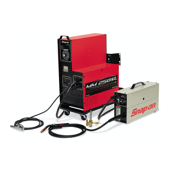
Page 1: Service Manual
MM250SL SERVICE MANUAL MM250SL-2000 ERIAL UMBERS ATER FORM WC5276 9/94 (Rev. 2/95, 1/96, 7/97, 9/97, 1/00) - Page 2 FIGURE D1 ....PRINTED CIRCUIT BOARD (SN-529U) ........16 ........PARTS LIST ................17 FIGURE D2 ....WIRE DRIVE ASSEMBLY (SN-138C24M) ....... 18 ........PARTS LIST ................19 FIGURE E ....FEEDER CABLE ASSEMBLY (FCA-15) ........20 ........PARTS LIST ................20 Snap-on Tools Corporation Kenosha, WI 53141-1410...
- Page 3 Snap-on Tools Corporation Kenosha, WI 53141-1410...
- Page 4 FIGURE 1A - SCHEMATIC, WIRE FEED CIRCUIT BOARD FIGURE 1B - SCHEMATIC, SPOT TIME CIRCUIT BOARD Snap-on Tools Corporation Kenosha, WI 53141-1410...
- Page 5 YELLOW ORANGE BLUE BROWN BLACK WHITE PURPLE GREEN FIGURE 2 - WIRING DIAGRAM, CONTROL CABLE ASSEMBLY Snap-on Tools Corporation Kenosha, WI 53141-1410...
- Page 6 FIGURE A - FRONT ASSEMBLY Snap-on Tools Corporation Kenosha, WI 53141-1410...
- Page 7 KNOB, HEAT ............................1 SN-319 CABLE HANGER ..........................2 SN-115 VOLTMETER (ROUND CORNERS) ....................1 SN-115A VOLTMETER (SQUARE CORNERS) (SERIAL# MM250SL-6020 AND LATER) ....... 1 SN-115L LENS, VOLTMETER (ROUND CORNERS) ..................1 SN-115AL LENS, VOLTMETER (SQUARE CORNERS) ..................1 SN-306M LEFT SIDE ............................
- Page 8 12 FIG. B1 FIGURE B - LEFT SIDE VIEW & INTERNAL COMPONENTS Snap-on Tools Corporation Kenosha, WI 53141-1410...
- Page 9 DIODE ..............................4 SN-162 RESISTOR, 100 OHM 25W ........................ 1 SN-360 HEAT SINK ASSEMBLY, COMPLETE ....................1 SN-360T HEAT SINK ASSEMBLY, COMPLETE (SERIAL# MM250SL-3949 AND LATER) ......1 SN-255M LEG, HEAT SINK ..........................2 SN-125S CAPACITOR, 12,000UF 50V ....................... 6 SN-286T TRANSFORMER, POWER .........................
- Page 10 FIGURE B1 - PRINTED CIRCUIT BOARD (SN-774U) Snap-on Tools Corporation Kenosha, WI 53141-1410...
- Page 11 CB-043 RESISTOR, 1K OHM 1/2W ......................... 2 MI-127 RESISTOR, 100 OHM 1/2W ....................... 1 MI-135A RESISTOR, TRIM 1 MEG OHM ......................1 MI-159 RESISTOR, 330 OHM 1/2W ....................... 1 CB-048 RECTIFIER, BRIDGE .......................... 1 Snap-on Tools Corporation Kenosha, WI 53141-1410...
- Page 12 FIGURE C - FRONT VIEW - REMOTE FEED UNIT Snap-on Tools Corporation Kenosha, WI 53141-1410...
- Page 13 " , (SERIAL# MM250SL-2729 AND LATER) ..................1 SN-5110C COMPLETE CABINET ASSEMBLY (MUST BE PURCHASED AS A COMPLETE ASSEMBLY) SN-700 BUMPER PAD, SELF-TAPPING (SERIAL# MM250SL-2572 AND LATER) ........2 SN-246B TERMINAL, GAS-CURRENT ......................1 SN-6190 RECEPTACLE, CONTROL (INPUT) ....................1 SN-5180 FRONT, FEED UNIT ...........................
- Page 14 11 FIG. D1 FIG. D2 FIGURE D - RIGHT SIDE VIEW & INTERNAL COMPONENTS REMOTE FEED UNIT Snap-on Tools Corporation Kenosha, WI 53141-1410...
- Page 15 SPOT TIMER BOARD (BEHIND COVER)(FIGURE D1) ..............1 SN-601 STAND OFF, NYLON (BEHIND COVER) ..................4 SN-5220 SPOOL BRACKET ..........................1 SN-5220A " (SERIAL# MM250SL-2729 AND LATER) ..................1 SN-22 SPOOL CLIP ............................. 1 SN-122 SPOOL HUB ASSEMBLY ......................... 1 SN-15 SHAFT ...............................
- Page 16 FIGURE D1 - PRINTED CIRCUIT BOARD (SN-529U) Snap-on Tools Corporation Kenosha, WI 53141-1410...
- Page 17 DIODE, 2A ............................3 MI-627 TRANSISTOR, PUT ..........................1 MI-125 RESISTOR, 4.7K OHM 1/2W ......................1 MI-148 RESISTOR, 1.2K OHM 1/2W ......................1 MI-126 RESISTOR, 3.3K OHM 1/2W ......................1 CB-048 RECTIFIER, BRIDGE .......................... 1 Snap-on Tools Corporation Kenosha, WI 53141-1410...
- Page 18 FIGURE D2 - WIRE DRIVE ASSEMBLY (SN-138C24M) Snap-on Tools Corporation Kenosha, WI 53141-1410...
- Page 19 DRIVE ROLL (30-45DR) ........................1 SN-61C 1/2 WOODRUFF DRIVE KEY ......................1 SN-131S MOTOR BRACKET, ADJUSTABLE ....................1 SN-139AD INSULATOR, TOP .......................... 1 SN-139 MOTOR BASE INSULATOR ......................1 SN-40 INSULATING WASHER ........................4 Snap-on Tools Corporation Kenosha, WI 53141-1410...
- Page 20 CABLE FITTING ..........................2 SN-023 WELD CABLE ONLY (14'-10") ......................1 SN-2157E-15 GAS/CURRENT CABLE ASSY., 15' EXTENSION ................1 SN-027-15 GAS HOSE ONLY , 15' ........................1 SN-2008 CABLE TIE ............................. 15 SN-807G BOOT/CABLE COVER ........................1 Snap-on Tools Corporation Kenosha, WI 53141-1410...
Need help?
Do you have a question about the MM250SL and is the answer not in the manual?
Questions and answers