Advertisement
INSTRUCTION MANUAL FOR WIRE WELDING MACHINE
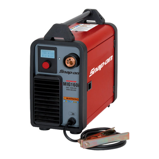
160 AMP MIG WELDER
MIG160i
INTRODUCTION
The MIG160i is a single-phase synergic inverter power source for MIG welding. This versatile
power source is suitable for various applications from general repairs to specifi c material types
used in the body shop industry. Welds a variety of material types and thicknesses such as steel,
stainless-steel, aluminum, high strength and boron steels. Preset synergic curves automatically
provide proper settings for individual situations and reduce set up times.
3.300.048/B
form WC 6000
Advertisement
Table of Contents

Related Manuals for Snap-On MIG160i


Summary of Contents for Snap-On MIG160i
- Page 1 MIG160i INTRODUCTION The MIG160i is a single-phase synergic inverter power source for MIG welding. This versatile power source is suitable for various applications from general repairs to specifi c material types used in the body shop industry. Welds a variety of material types and thicknesses such as steel, stainless-steel, aluminum, high strength and boron steels.
-
Page 2: Table Of Contents
TABLE OF CONTENTS Introduction ..............................Front Cover Table of Contents ................................2 Safety Information ............................... 3-4 Specifications ..................................5 Features ...................................6 Description of Equipment ..............................6 Assembling the Unit ..............................7-9 Quick start guide ............................... 9-11 Advanced setting ..............................11-12 Maintenance ..................................13 Replacement Parts ..............................14-15 Wiring Diagram ................................16 Warranty/Service and Repair............................17... -
Page 3: Safety Information
SAFETY INFORMATION MUST READ INSTRUCTIONS BEFORE USE Arc Welding Read, understand and follow all safety messag- es and instructions in this manual. Safety mes- sages in this section of the manual contain a sig- Electric welding or plasma cutting causes ultra- nal word with a three-part message and, in some violet rays and weld spatter. - Page 4 SAFETY INFORMATION cont'd Risk of Explosion Disposal of Equipment IMPORTANT Disposal of electrical equipment can be hazard- Welding causes sparks that can cause explo- ous to the environment. sion. Contact local regulations prior to disposal. Use caution and proper procedures when Improper disposal can cause an environmental welding.
-
Page 5: Specifications
SPECIFICATIONS GENERAL DESCRIPTIONS SPECIFICATIONS Power Input This welding machine is a power source developed with Voltage 230 Volt inverter technology, suitable for MIG welding. This welding machine must not be used to defrost pipes. Phase Single Phase Frequency 50/60 Hertz EXPLANATION OF TECHNICAL SPECIFICATIONS Current 20 Amps... -
Page 6: Features
FEATURES • Compact inverter-style wire feed synergic MIG welder. • Easy to read LCD display panel and single-knob for selection and adjustments. • Multiple synergic curves allow you to weld a variety of materials and thicknesses. • Preset synergic curves automatically provide the proper settings to each individual situation. •... -
Page 7: Assembling The Unit
3 and 4. • Cut the wire with a Snap-on cutting pliers 87ACF or equivalent, keeping it between your fingers so that it cannot unwind, insert it inside the plastic tube exiting... - Page 8 ASSEMBLING THE UNIT cont'd PREPARING THE STEEL TORCH FOR WELDING ALUMINUM USING OPTIONAL ALUMINUM KIT (MIG 160AK) AND OPTIONAL ROLLER (CKS 3080942). Electrical shock can result when contacting live electrode or internal components •Remove the metal liner Electrical shock can result from absence of located inside the wel- grounding lug.
-
Page 9: Quick Start Guide
ASSEMBLING THE UNIT cont'd DIFFERENT TYPES of WIRE • Aluminum (AlMg5-5356 and AlSi12-4047) It is possible to weld on thicknesses of .030" to 0.24". • Flux cored wire Therefore this is widely used in the car body repair, but This is typically used for outdoor repairs on steel struc- also to repair boats and other aluminum structures. - Page 10 QUICK START GUIDE cont'd SYNERGIC CURVE (WIRE SELECTION): Wire Material Setting Composition Shielding Gas Application Thickness E71TGS .035 Flux Core - none .040 to .200 All-purpose steel welding from sheet metal to Steel strutural .023 Steel 75% Argon .023 to .200 All-purpose steel welding from thin sheet to 25%CO2 strutural...
-
Page 11: Advanced Setting
QUICK START GUIDE cont'd With more wire out (stick out), you have a more concentrated By changing the value, once having exited the sub-menu, arc that generates a higher, more pronounced and a alongside the voltage V, an arrow will appear turned slightly stretched out weld bead;... - Page 12 ADVANCED SETTING cont'd • Inductance • LCD Contrast Adjustment can vary from -9.9 to +9.9. Factory setting is zero. If the figure is negative, the impedance drops and the arc becomes cooler, while if it increases, the arc is hotter. To access this function, simply highlight it using the knob and press it for less than 2 seconds.
-
Page 13: Maintenance
MAINTENANCE WELDER MAINTENANCE Electrical shock can result when contacting live electrode or internal components Electrical shock can result from absence of grounding lug. Welding machine must be connected to power source in accordance with applicable electrical codes. Do not touch electrode or internal compo- nents without protection. -
Page 14: Replacement Parts
REPLACEMENT PARTS – PARTS LIST... - Page 15 CKS246946 STRAIN RELIEF CKSB7018380 WHEN ORDERING SPARE PARTS PLEASE STATE THE MODEL NUMBER AND SERIAL NUMBER AND PART NUMBER NEEDED. PART N. DESCRIPTION MIG160i TORCH CONSUMABLES TORCH# MIG1605 + MIG1606 HEAVY DUTY TORCH ASS'Y MIG1608 PART N. DESCRIPTION STANDARD TORCH ASS'Y MIG1605 .023 (0.6mm) contact tip.
-
Page 16: Wiring Diagram
WIRING DIAGRAM... -
Page 17: Warranty/Service And Repair
Snap-on Tools Company Limited Two (2) Year Warranty Snap-on Tools Company (the “Seller") warrants only to original purchasers who use the Equipment in their business that under normal use, care and service, the Equipment (except as otherwise provided herein) shall be free from defects in material and workmanship for two years from the date of original invoice. - Page 18 MIG1606 ALUMINUM TORCH INSTALLATION 1. Remove the steel welding wire and torch assembly if installed. 2. Remove the steel drive roller by loosening the set screw. 3. Remove the set screw and install into the aluminum drive roller (part number CKS3080942). Install with the .035” U-groove toward the inside of the welder and Jghten the set screw. 4. Remove the brass tube in the torch housing and save. The tube needs to be installed when using all other welding wire but aluminum. 5. Install the aluminum torch. The liner sJck out should just stop just short of the drive roller. 6. Install the enclosed aluminum .035” wire and feed it into the guide tube and then into the torch liner. 7. Close the drive arm and be careful that the aluminum wire is aligned in the roller grove. Very Important! Do not over increase the wire roller tension with the tension knob. This will cause the wire to “bird nest” between the roller and the liner. The factory adjustment should be the correct tension exposing approximately four rings. 8. Set the synergic curve for ALMG5 .035” 100% Argon. 9. Install the flow regulator to a tank of 100% Argon and adjust the flow to 40 CFH. 10. Set the material thickness and you are ready to weld.
Need help?
Do you have a question about the MIG160i and is the answer not in the manual?
Questions and answers