Table of Contents
Advertisement
Available languages
Available languages
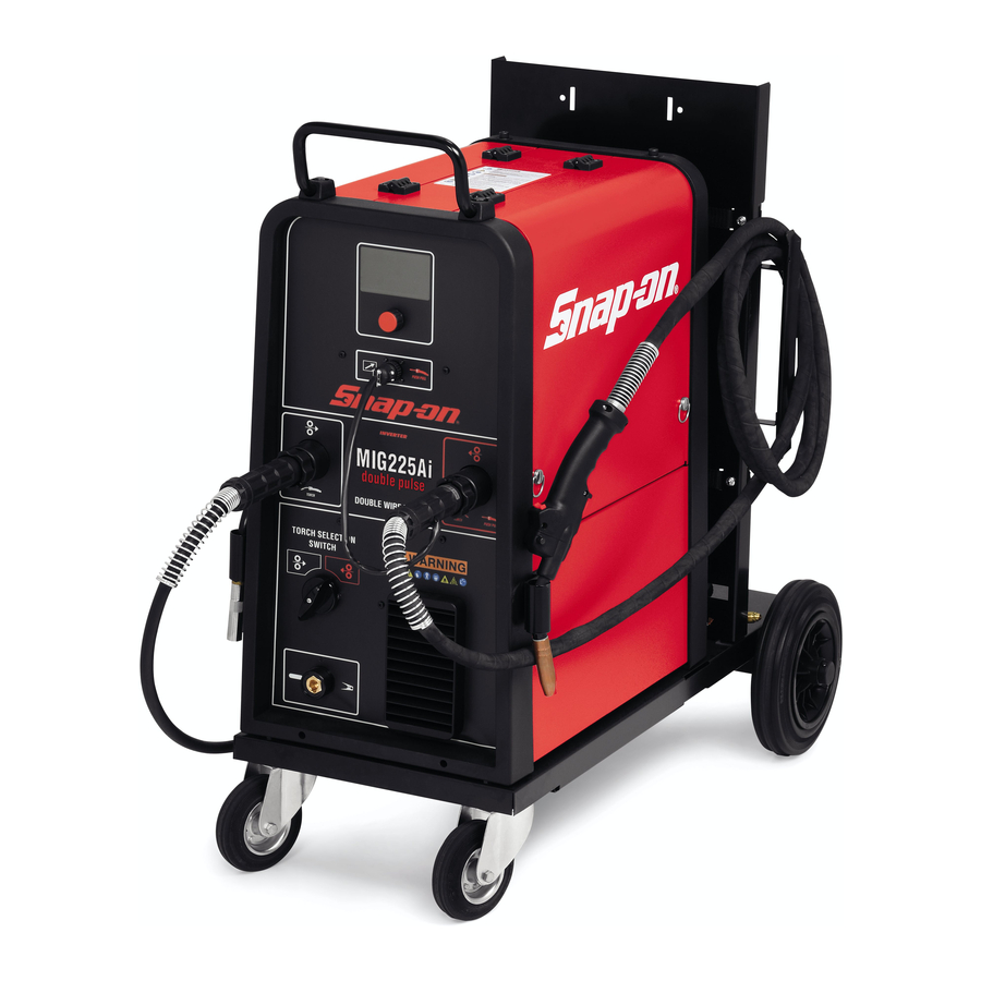
225 AMP DOUBLE PULSE MIG WELDER
WITH DOUBLE WIRE FEEDERS
MIG225Ai
INTRODUCTION
The MIG225Ai double pulse is a 230VAC single-phase synergic inverter power source for MIG wel-
ding. This versatile power source is suitable for various applications from general repairs to specific
material types used in the body shop industry. Welds a variety of material types and thicknesses
such as steel, stainless-steel, aluminum, high strength and boron steels. Preset synergic curves
automatically provide proper settings for individual situations and reduce set up times.
3301056
Advertisement
Chapters
Table of Contents

Related Manuals for Snap-On MIG225Ai


Summary of Contents for Snap-On MIG225Ai
- Page 1 MIG225Ai INTRODUCTION The MIG225Ai double pulse is a 230VAC single-phase synergic inverter power source for MIG wel- ding. This versatile power source is suitable for various applications from general repairs to specific material types used in the body shop industry. Welds a variety of material types and thicknesses such as steel, stainless-steel, aluminum, high strength and boron steels.
-
Page 2: Table Of Contents
TABLE OF CONTENTS Introduction ..............................Front Cover Table of Contents ................................2 Safety Information ............................... 3-4 Specifications ..................................5 Features ...................................5 Description of Equipment ..............................6 Assembling the Unit ..............................7-8 Quick start guide ................................. 8-9 Advanced setting ..............................10-12 Maintenance ..................................13 Replacement Parts ................................14 Wiring Diagram ................................17 Warranty/Service and Repair............................18... - Page 3 SAFETY INFORMATION MUST READ INSTRUCTIONS BEFORE USE Arc Welding Read, understand and follow all safety messag- es and instructions in this manual. Safety mes- sages in this section of the manual contain a sig- Electric welding or plasma cutting causes ultra- nal word with a three-part message and, in some violet rays and weld spatter.
- Page 4 SAFETY INFORMATION cont'd Risk of Explosion ITEMS REQUIRED FOR MIG WELDING WHICH ARE NOT PROVIDED WITH THE MIG225i. 1. Full cover welding helmet with proper colored lens (shade 9 to 11, depending on operator's preference). Welding causes sparks that can cause explosion. 2.
-
Page 5: Specifications
SPECIFICATIONS GENERAL DESCRIPTIONS SPECIFICATIONS Power Input This welding machine is a power source developed with Voltage 230 Volt inverter technology, suitable for MIG welding. This welding machine must not be used to defrost pipes. Phase Single Phase Frequency 50/60 Hertz EXPLANATION OF TECHNICAL SPECIFICATIONS Current 26 Amps... -
Page 6: Features
• Adjustable Arc Length, HSA, CRA, Inductance, Burnback, Soft Start, Pre Gas and Post Gas. • Faster set up time and reduced production times. • Over 30 years of industry-leading technical support by calling 800-ABC-WELD DESCRIPTION OF EQUIPMENT PUSH PULL INVERTER MIG225Ai double pulse DOUBLE WIRE FEEDER TORCH TORCH PUSH PULL... -
Page 7: Assembling The Unit
DESCRIPTION OF EQUIPMENT DISPLAY SCREEN CONNECTOR Connector for the connection of This displays both the welding parameters and Push-pull welding functions. POWER INPUT CORD MULTI-FUNCTION KNOB SWITCH Selects and adjusts both the welding functions and parameters. GAS SUPPLY CONNECTION CENTRALIZED COUPLING Welding torch connection CENTRALIZED COUPLING Welding torch connection + Push Pull... -
Page 8: Quick Start Guide
ASSEMBLING THE UNIT cont'd be welded, following the instructions given in the service nominal thickness, distance between current nozzle and functions (PROCESS PARAMS) paragraph. Remove the the material being welded, and the welding speed. After gas nozzle and unscrew the contact tip of the torch. Press welding, the current and voltage values remain stored on the torch button until the wire comes out. - Page 9 QUICK START GUIDE SYNERGIC CURVE (WIRE SELECTION) Material Thickness Shielding Setting Wire Composition MIN/MAX inch Application SHORT PULSED .023” Steel 75% Argon .024”-.118” .028”-.138” All-purpose steel welding from thin sheet 25% CO2 0.6 - 3mm 0.7 – 3.5mm to structural .023”...
-
Page 10: Advanced Setting
ADVANCED SETTING Mode 3L Specially well suited to weld aluminium. To access these functions, we must start from the main 3 currents are available that can be used in welding by display page and press the knob for at least 2 seconds. means of the weling torch start button. - Page 11 ADVANCED SETTING cont'd (Crater Curr.) from 10 to 200% of the welding current (Default 60%). The time (C.C. Time) of the crater filling duration may also be adjusted from 0.1 to 10 seconds (default 0.5 seconds). • Double Pulse This type of welding varies the intensity of the current between two levels and can be included in all synergic •...
- Page 12 ADVANCED SETTING cont'd • AUTO burnback The adjustment can vary from -9.9 to +9.9. Its purpose is to adjust the length of the wire coming out of the gas nozzle after welding. A positive figure corresponds to greater wire burning. Default is Auto (preset function).
-
Page 13: Maintenance
• Post Gas To access the function, simply highlight it using the knob . By pressing this for less than 2 seconds, the display screen shows the words OFF and ALL. By highlighting the word ALL and briefly pressing the knob B reset is made and the display screen shows Factory Done!! This indicates the reset has been... -
Page 14: Replacement Parts
REPLACEMENT PARTS – PARTS LIST... - Page 15 REPLACEMENT PARTS – PARTS LIST PART N. DESCRIPTION PART N. DESCRIPTION CKS246272 EARTH CABLE CKSB7116370 FITTING CKS3070340 FRAME CKS5812736 BACK PANEL CKSM16001 FINNED PANEL CKS5710910 MOTOR WITH FAN CKS5803996 HANDLE CKS3063407 MOTOR WITH FAN\SUPPORT CKS3060095 HANDLE SUPPORT CKS5602279 CIRCUIT CKS5710369 LEFT WIRE FEED MOTOR CKS3070129 COVER...
- Page 16 WHEN ORDERING SPARE PARTS PLEASE STATE THE MODEL NUMBER AND SERIAL NUMBER AND PART NUMBER NEEDED. PART N. DESCRIPTION MIG185i-MIG225i TORCH CONSUMABLES TORCH# MIG1855 + MIG1856 TORCH ASS'Y MIG1855 PART N. DESCRIPTION ALUMINUM TORCH ASS'Y STANDARD MIG1856 .023 (0.6mm) contact tip. 10pack MIG18523 .023 (0.6mm) contact tip.
-
Page 17: Wiring Diagram
WIRING DIAGRAM... -
Page 18: Warranty/Service And Repair
Snap-on Tools Company Limited Two (2) Year Warranty Snap-on Tools Company (the “Seller") warrants only to original purchasers who use the Equipment in their business that under normal use, care and service, the Equipment (except as otherwise provided herein) shall be free from defects in material and workmanship for two years from the date of original invoice. - Page 19 PUSH-PULL GUN MIG225PP 3.300.501 form WC 6226...
- Page 20 TABLE OF CONTENTS Introduction ..............................Front Cover Table of Contents ................................2 Safety Information ............................... 3-4 Specifications ..................................5 Assembling the Unit ..............................5-6 Welding ....................................7 Replacement Parts ..............................8-9 Wiring Diagram ................................9 Warranty/Service and Repair............................10...
-
Page 21: Safety Information
SAFETY INFORMATION MUST READ INSTRUCTIONS BEFORE USE Arc Welding Read, understand and follow all safety messag- es and instructions in this manual. Safety mes- sages in this section of the manual contain a sig- Electric welding or plasma cutting causes ultra- nal word with a three-part message and, in some violet rays and weld spatter. - Page 22 SAFETY INFORMATION cont'd Risk of Explosion Disposal of Equipment IMPORTANT Disposal of electrical equipment can be hazard- Welding causes sparks that can cause explosion. ous to the environment. Use caution and proper procedures when Contact local regulations prior to disposal. welding.
-
Page 23: Specifications
SPECIFICATIONS GENERAL DESCRIPTIONS The duty cycle is 160 A at 40%. The maximum welding current is 200 A at 20% of duty The welding torch PUSH-PULL is designed to facilitate cycle. welding of aluminium wires. Minimum and maximum speed are (1.4 - 20 mpm) – (55 Torches are provided with an internal thermoplastic - 790 IPM). - Page 24 ASSEMBLING THE UNIT cont'd Check that the wire is placed inside the wire feed roller Press the lever to remove roller groove and then release the lever so that the Unscrew the gas nozzle and the contact tip wire pressure bearing presses the wire onto the Press the lever to raise the wire press bearing...
-
Page 25: Welding
WELDING Make sure that the welding machine is set for the wire diameter and type of aluminium to be welded. Make sure that the PUSH-PULL welding torch. Has the correct roller with fine diameter corresponding to the wire being used and installed the right contact tip. -
Page 26: Replacement Parts
REPLACEMENT PARTS – PARTS LIST WHEN ORDERING SPARE PARTS PLEASE STATE THE MODEL NUMBER AND SERIAL NUMBER AND PART NUMBER NEEDED. -
Page 27: Wiring Diagram
REPLACEMENT PARTS – PARTS LIST PART N. DESCRIPTION PART N. DESCRIPTION CONNECTION SPRING CKS3115101 SWITCH CONNECTOR CKS3170241 CKS3190436 UP-DOWN CIRCUIT WIRE INLET GUIDE CKS3065216 CKS5602029 KIT NIPPLE+OR+TEFLON RH HANDGRIP CKS5710062 CKS5710294 WIRE INLET GUIDE SHEATH HOSE SPRING CKS3065214 CKS3115100 CURRENT/GAS PIPE LEVER CKS3120014 CKS3065215... -
Page 28: Warranty/Service And Repair
Snap-on Tools Company Limited 30 days Warranty Snap-on Tools Company (the "Seller") warrants only to original purchasers who use the Equipment in their business that under normal use, care and service, the Equipment (except as otherwise provided herein) shall be free from defects in material and workmanship for 30 days from the date of original invoice. - Page 29 MIG 225Ai INTRODUCTION Le MIG225Ai double pulsé est un poste de soudage à technologie inverseur synergique 230VAC mono- phasé pour soudage MIG. Ce poste de soudage particulièrement polyvalent s'adapte à diverses appli- cations, allant des réparations en général à différentes sortes de matériaux utilisés dans l'industrie de la carrosserie.
- Page 30 TABLE DES MATIÈRES Introduction ...................................18 Table des matières ................................19 Informations sur la sécurité ............................. 20-21 Caractéristiques techniques ............................22 Particularités ..................................23 Description de l'équipement ............................23 Assemblage de l'unité ..............................25 Guide de démarrage ..............................27 Paramètres avancés ..............................30 Maintenance ..................................31 Pièces de rechange ...............................32 Schéma de câblage ...............................35 Garantie/Service et réparation ............................36...
-
Page 31: Informations Sur La Sécurité
INFORMATIONS SUR LA SÉCURITÉ LILISEZ LES INSTRUCTIONS AVANT D'UTILISER Lors de l'utilisation de soudeuses électriques L'APPAREIL ou de coupeurs plasma, porter un casque de soudage muni de verres filtrants appropriés. Veuillez lire, bien comprendre et suivre toutes les Tenir les spectateurs à distance au cours du instructions de ce manuel. - Page 32 INFORMATIONS SUR LA SÉCURITÉ (suite) Risque d'explosion ELEMENTS REQUIS POUR LE SOUDAGE MIG QUI NE SONT PAS FOURNIS AVEC LE MIG225i. 1. Casque de soudage à couverture totale muni de verres filtrants appropriés (filtre de 9 à 11, en fonction Le soudage génère des étincelles qui peuvent de la préférence de l'opérateur).
-
Page 33: Caractéristiques Techniques
CARACTERISTIQUES DESCRIPTION GÉNÉRALE CARACTERISTIQUES TECHNIQUES Alimentation Cette machine de soudage est un poste conçu avec une Tension 230 Volt technologie inverseur, adaptée au soudage MIG. Ce poste de soudage ne doit pas être utilisé pour dégeler Phase Monophasé la tuyauterie. Fréquence 50/60 Hertz Courant... -
Page 34: Particularités
• Arc Length, HSA, CRA, Inductance, Burnback, Soft Start, Pre Gas et Post Gas réglables. • Temps de préparation plus rapides et temps de production réduits • Plus de 30 ans d'assistance technique de pointe en appelant 800-ABC-WELD DESCRIPTION DE L'ÉQUIPEMENT PUSH PULL INVERTER MIG225Ai double pulse DOUBLE WIRE FEEDER TORCH TORCH PUSH PULL... -
Page 35: Assemblage De L'unité
DESCRIPTION DE L'ÉQUIPEMENT CORDON D'ALIMENTATION ÉLECTRIQUE ÉCRAN D'AFFICHAGE Celui-ci affiche à la fois les paramètres de soudage INTERRUPTEUR D'ALIMENTATION et les fonctions de soudage. RACCORDEMENT D'ARRIVÉE DE GAZ BOUTON MULTIFONCTION Sélectionne et règle à la fois les paramètres de soudage et les fonctions de soudage. RACCORDEMENT CENTRALISÉ... -
Page 36: Guide De Démarrage
ASSEMBLAGE DELL'UNITÉ bien à la valeur nominale du poste à souder. Exigences ge du rouleau d’entraînement et doit sortir de l’adapta- électriques: 230VAC 30 Amp service. Dimensionner les teur . Fermer le bras d’entraînement, monter la torche fusibles de protection d’après les données indiquées sur de soudure et le câble de masse sur la prise la plaquette des données techniques. - Page 37 GUIDE DE DÉMARRAGE (suite) SYNERGIQUE COURBE (SÉLECTION DU FIL) Épaisseur matériau Gaz de COURBE SYNERGIQUE (SÉLECTION DU FIL) MIN-MAX inch Réglage Dia Fil Composition Application protection Short Pulsed Acier .023” 75% Argon .024”-.118” .028”-.138” Soudage acier tout usage, de la feuille 25% CO2 0.6 - 3mm 0.7 –...
-
Page 38: Paramètres Avancés
PARAMÈTRES AVANCÉS Pour accéder à ces fonctions, il faut partir de la page écran principale et appuyer pendant au moins 2 secondes sur le bouton Pour entrer à l'intérieur de la fonction, il suffit de la sélectionner avec le bouton et appuyer dessus pendant au moins 2 secondes. - Page 39 PARAMÈTRES AVANCÉS (suite) • CRA (crater filler- remplissage du cratère final). barre de réglage, le temps de pause entre deux points Cette fonction est bloquée quand la fonction 3L est ou deux traits de soudage ; le temps de pause peut active.
- Page 40 PARAMÈTRES AVANCÉS utilisant le bouton et en appuyant dessus pendant moins de 2 secondes, l'écran affiche la barre de réglage ; on peut changer la valeur et la confirmer en appuyant toujours sur le bouton pendant moins de 2 secondes. •...
-
Page 41: Maintenance
• Post Gas fourniture. Pour accéder à la fonction, il suffit de la sélectionner en utilisant le bouton ;en appuyant dessus pendant moins de 2 secondes, l'écran affiche OFF et ALL; en sélectionnant ALL et en appuyant brièvement sur le bouton , on fait la remise à... -
Page 42: Pièces De Rechange
PIÈCES DE RECHANGE – LISTE DES PIÈCES... - Page 43 PIÈCES DE RECHANGE – LISTE DES PIÈCES N° PIÈCE DESCRIPTION N° PIÈCE DESCRIPTION CKS246272 CABLE TERRE CKS5812736 PANNEAU ARRIÈRE CKS3070340 CADRE CKS5710910 MOTEUR AVEC FAN CKSM16001 PANNEAU À AILETTES CKS3063407 MOTEUR AVEC FAN \ SUPPORT CKS5803996 MANIPULER CKS5602279 CIRCUIT CKS3060095 SUPPORT POIGNÉE CKS3070129 COUVERTURE...
- Page 44 LORS DE LA COMMANDE DE PIÈCES DE RECHANGE VEUILLEZ INDIQUER LE NUMÉRO ET LA SÉRIE DU MODÈLE ET LA RÉFÉRENCE NÉCESSAIRE. N° PIÈCE DESCRIPTION MIG185i-MIG225i CONSUMABLES TORCHE TORCHE# MIG1855 + MIG1856 TORCHE KIT MIG1855 N° PIÈCE DESCRIPTION TORCHE KIT, ALUMINIUM MIG1856 Electrode 0.6mm (.023").
-
Page 45: Schéma De Câblage
SCHÉMA DE CÂBLAGE... -
Page 46: Garantie/Service Et Réparation
Garantie de Snap-on Tools Company limitée à deux (2) ans. Snap-on Tools Company (le « Vendeur ») garantit uniquement aux acheteurs initiaux qui utilisent l'équipement dans leur entreprise dans des conditions normales d'utilisation, de soins et d'entretien, que l'équipement (sauf disposition contraire dans les présentes) est exempt de défauts de matériaux et de fabrication, pendant deux ans, à... - Page 47 MIG 225i INTRODUCTION El MIG225Ai double pulse es un generador inverter 230VAC monofásico sinérgico para soldadura MIG. Este generador versátil es adecuado para diferentes aplicaciones, desde reparaciones en ge- neral hasta tipos específicos de materiales usados en el sector de talleres de carrocerías. Suelda una variedad de tipos y espesores de materiales tales como acero, acero inoxidable, aluminio de alta resistencia y aceros al boro.
- Page 48 TABLA DE CONTENIDO Introducción ..................................35 Tabla de Contenido ...............................36 Información sobre Seguridad ............................37 Especificaciones ................................39 Características ................................40 Descripción del Equipo ..............................40 Montaje de la Unidad ..............................41 Guía de Arranque Rápido ..............................42 Configuraciones Avanzadas ............................44 Mantenimiento ................................49 Piezas de Recambio ..............................50 Diagrama de Cableado ..............................53 Garantía/Servicio y Reparación .............................54...
-
Page 49: Información Sobre Seguridad
INFORMACIÓN SOBRE SEGURIDAD ES NECESARIO LEER LAS INSTRUCCIONES ANTES Soldadura de arco DEL USO Es necesario leer, comprender cabalmente y aplicar todos los mensajes sobre seguridad y las La soldadura eléctrica y el corte al plasma des- instrucciones de este manual. Los mensajes de piden rayos ultravioleta y salpicaduras de solda- seguridad de esta sección del manual contienen dura. - Page 50 INFORMACIÓN SOBRE SEGURIDAD Riesgo de Descarga Eléctrica No enrollar el cable del electrodo/antorcha en torno al propio cuerpo. No trabajar en proximidad de la fuente de ali- mentación de soldadura/corte. El contacto con componentes internos o el elec- Descarga eléctrica y campos magnéticos pue- trodo en vivo puede provocar la recepción de den causar lesiones.
-
Page 51: Especificaciones
ESPECIFICACIONES DESCRIPCIONES GENERALES ESPECIFICACIONES Entrada Energía Esta soldadora es una fuente de energía desarrollada con Tensión 230 Voltios tecnología inverter, adecuada para la soldadura MIG. Esta máquina de soldadura no debe ser utilizada para Fase Monofásica descongelar tuberías. Frecuencia 50/60 Hz Corriente 26 Amperios EXPLICACIÓN DE LOS DATOS TÉCNICOS EXPUES-... -
Page 52: Características
• Más de 30 años de liderazgo en el soporte técnico para de soldadura tales como: corriente, tensión, espesor re- la industria llamando al 800-ABC-WELD comendado, velocidad del hilo y diámetro del hilo. DESCRIPCIÓN DEL EQUIPO PUSH PULL INVERTER MIG225Ai double pulse DOUBLE WIRE FEEDER TORCH TORCH PUSH PULL TORCH SELECTION... -
Page 53: Montaje De La Unidad
DESCRIPCIÓN DEL EQUIPO PANTALLA EXPOSITORA DE DATOS INTERRUPTOR PARA LA SELECCIÓN DE ACO- Aquí se indican tanto los parámetros como las fun- PLAMIENTO CENTRALIZADO ciones de soldadura. CONECTOR para la conexión de Push-pull MANDO MULTIFUNCIÓN CABLE DE ALIMENTACIÓN Selecciona y regula tanto las funciones como los parámetros de soldadura. -
Page 54: Guía De Arranque Rápido
MONTAJE DE LA UNIDAD interior del moto reductor, asegurándose de que el tipo y y la tensión efectiva de trabajo, los valores visualizados el diámetro del hilo sean los mismos del rodillo de arras- pueden ser ligeramente diferentes de los valores pro- tre. - Page 55 GUÍA DE ARRANQUE RÁPIDO CURVA SYNÉRGICA (SELECCIÓN DE HILO) Épaisseur matériau Gaz de MIN-MAX inch Réglage Dia Fil Composition Application protection Short Pulsed .023” Acero 75% Argon .024”-.118” .028”-.138” Todas las posibles soldaduras en acero, desde 25% CO2 0.6 - 3mm 0.7 –...
-
Page 56: Configuraciones Avanzadas
CONFIGURACIÓN AVANZADA Para acceder a estas funciones es necesario partir de la pantalla principal y presionar durante al menos 2 segun- dos la manecilla Para entrar en la función es suficiente seleccionarla con la manecilla y presionar la misma por menos de 2 se- gundos. - Page 57 CONFIGURACIÓN AVANZADA po de pausa entre un punto o un trecho de soldadura y • CRA (crater filler- llenado del cráter final). el otro, el tiempo de pausa varía de 0 (OFF) a 5 segun- Esta función permanece inhibida mientras la función dos.
- Page 58 CONFIGURACIÓN AVANZADA cambiar su valor (ajuste de 25 a 75%) (predeterminado • Burnback AUTO 50%). El ajuste puede variar desde -9,9 a +9,9. Sirve para Gire la perilla para seleccionar la longitud del arco de la regular la longitud del hilo que sale de la tobera gas corriente principal.
-
Page 59: Mantenimiento
• Post Gas usando la manecilla y presionándola por menos de 2 segundos, en el display aparecen las letras OFF y ALL, evidenciando las letras ALL y presionan- do brevemente la manecilla se efectúa el reinicio y en el display aparecen las letras Factory Done!! que demuestran que el reinicio ha sido efectuado. - Page 60 DESPIECE - LISTA DE LOS REPUESTOS...
- Page 61 DESPIECE - LISTA DE LOS REPUESTOS PART N. DESCRIPCIÓN PART N. DESCRIPCIÓN CKS246272 CABLE MASA CKSB7116370 ADECUADO CKS3070340 MARCO CKS5812736 PANEL POSTERIOR CKSM16001 PANEL ALETADO CKS5710910 MOTOR CON VENTILADOR CKS5803996 MANGO CKS3063407 MOTOR CON VENTILADOR \ SOPORTE CKS3060095 SOPORTE MANGO CKS5602279 CIRCUITO CKS5710369...
- Page 62 PARA EFECTUAR PEDIDOS DE RECAMBIOS SÍRVASE INDICAR NÚMERO DEL MODELO, NÚMERO DE SERIE Y NÚMERO DEL RECAMBIO REQUERIDO PIEZA Nº DESCRIPCIÓN MIG185i-MIG225i MATERIALES DE CONSUMO ANTOR- CHA TORCH# MIG1855 + MIG1856 CONJUNTO ANTORCHA MIG1855 .040 (1.0 mm) punta de contacto. MIG18540 KIT ANTORCHA, ALUMINIO ESTÁNDAR MIG1856...
-
Page 63: Diagrama De Cableado
DIAGRAMA DE CABLEADO... -
Page 64: Garantía/Servicio Y Reparación
Garantía Limitación Dos (2) Años Snap-on Tools Company Snap-on Tools Company (el “Vendedor") garantiza únicamente a favor de los compradores originales que utilizan el Equipo en sus propias empresas el hecho de que, en condiciones normales de uso, cuidado y mantenimiento, el Equi- po (salvo disposición en contrario en el presente documento) estará... - Page 66 Snap-on Tools Company Kenosha, Wisconsin 53141-1410 Technical Support Line 800-ABC-WELD Customer Service and Technical Support 800-ABC-WELD Monday – Friday 7:00 a.m. – 3:00 p.m. EST...
Need help?
Do you have a question about the MIG225Ai and is the answer not in the manual?
Questions and answers