Advertisement
200 AMP PULSE MIG WELDER
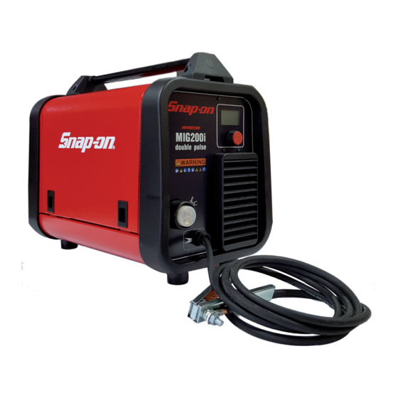
MIG200i
INTRODUCTION
The MIG200i Pulse is a 230VAC single-phase synergic inverter power source for MIG welding. This
versatile power source is suitable for various applications from general repairs to specifi c material
types used in the body shop industry. Welds a variety of material types and thicknesses such as
steel, stainless-steel, aluminum, high strength and boron steels. Preset synergic curves automati-
cally provide proper settings for individual situations and reduce set up times.
3301025
Advertisement
Table of Contents

Related Manuals for Snap-On MIG200i


Summary of Contents for Snap-On MIG200i
- Page 1 MIG200i INTRODUCTION The MIG200i Pulse is a 230VAC single-phase synergic inverter power source for MIG welding. This versatile power source is suitable for various applications from general repairs to specifi c material types used in the body shop industry. Welds a variety of material types and thicknesses such as steel, stainless-steel, aluminum, high strength and boron steels.
-
Page 2: Table Of Contents
TABLE OF CONTENTS Introduction ..............................Front Cover Table of Contents ................................2 Safety Information ............................... 3-4 Specifications ..................................5 Features ...................................6 Description of Equipment ..............................6 Assembling the Unit ..............................7-9 Quick start guide ............................... 9-11 Advanced setting ..............................11-14 Maintenance ..................................15 Replacement Parts ..............................16-18 Wiring Diagram ................................19 Warranty/Service and Repair............................20... -
Page 3: Safety Information
SAFETY INFORMATION MUST READ INSTRUCTIONS BEFORE USE Arc Welding Read, understand and follow all safety messag- es and instructions in this manual. Safety mes- sages in this section of the manual contain a sig- Electric welding or plasma cutting causes ultra- nal word with a three-part message and, in some violet rays and weld spatter. - Page 4 SAFETY INFORMATION cont'd Risk of Explosion Disposal of Equipment IMPORTANT Disposal of electrical equipment can be hazard- Welding causes sparks that can cause explosion. ous to the environment. Use caution and proper procedures when Contact local regulations prior to disposal. welding.
-
Page 5: Specifications
SPECIFICATIONS GENERAL DESCRIPTIONS SPECIFICATIONS Power Input This welding machine is a power source developed with Voltage 230 Volt inverter technology, suitable for MIG welding. This welding machine must not be used to defrost pipes. Phase Single Phase Frequency 50/60 Hertz EXPLANATION OF TECHNICAL SPECIFICATIONS Current 26 Amps... -
Page 6: Features
FEATURES • Compact inverter-style wire feed synergic MIG welder. • Easy to read LCD display panel and single-knob for selection and adjustments. • Multiple synergic curves allow you to weld a variety of materials and thicknesses. • Preset synergic curves automatically provide the proper settings to each individual situation. •... -
Page 7: Assembling The Unit
ASSEMBLING THE UNIT Position the welding machine so as to allow the free circulation REEL FITTING SEQUENCE of air inside and, as much as possible, prevent metal or other dusts from penetrating. • Electrical supply: ensure that there is a 208 or 230 volt, single phase, 30 ampere electrical supply within easy reach of the unit. - Page 8 ASSEMBLING THE UNIT cont'd • Close the drive arm, being careful of the wire, which SET-UP FOR STEEL WELDING must be aligned with the roller race,. • Fit the welding torch. •Insert the wire guide After fi tting the reel and torch, switch on the machine, select tube supplied along with the suitable synergic curve, following the instructions given the welding machine in-...
-
Page 9: Quick Start Guide
ASSEMBLING THE UNIT cont'd • Stainless Steel 308L This is typically used to repair many applications in- cluding stainless steel tanks and containers with a thickness of .031" to .177". • Aluminum (AlMg5-5356 and AlSi12-4047) It is possible to weld on thicknesses of .031" to .276". Therefore this is widely used in the car body repair, but also to repair boats and other aluminum structures. - Page 10 QUICK START GUIDE cont'd SYNERGIC CURVE (WIRE SELECTION) Material Thickness Shielding Setting Wire Composition MIN/MAX inch Application SHORT PULSED E71TGS .035 Flux Core - Steel none All-purpose steel welding from sheet metal 039 - .240 to structural 1 – 6 mm .023”...
-
Page 11: Advanced Setting
QUICK START GUIDE cont'd 4- ADJUSTING WELDING VOLTAGE (ARC change welding LENGTH) voltage V, simply press the knob for less than 2 seconds. The display screen will show (Arc Length) an adjustment bar with central 0. The value can be changed by means of the knob If the wire tends to disappear within the gas nozzle while you from -9.9 to 9.9. - Page 12 ADVANCED SETTING cont'd adjust the starting current (Start Curr) from 10 to 200% of the welding current (Default 130%). The duration of this current (S.C. Time) may also be adjusted from 0.1 to 10 seconds (default 0,5 sec.). The switching time (Slope Time) between the starting current (Start Curr) and the welding current may also be adjusted from 0.1 to 10 seconds (default 0.5 seconds.).
- Page 13 ADVANCED SETTING cont'd recommended to obtain the optimal penetration and width of the bead for the joint to be made. This type of welding varies the intensity between two levels. Before setting the double level welding, it is necessary to make a short bead to determine the wire speed and the current to obtain the penetration and the bead width closest to the type of welding to be made.
- Page 14 . By pressing this for less than 2 seconds, the display screen shows the words OFF and ALL. By highlighting the word ALL and briefly pressing the knob reset is shows Factory Done!! made and the display screen This indicates the reset has been successful. To return to the previous display page, simply press the knob more than 2 seconds.
-
Page 15: Maintenance
MAINTENANCE WELDER MAINTENANCE Electrical shock can result when contacting live electrode or internal components Electrical shock can result from absence of grounding lug. Welding machine must be connected to power source in accordance with applicable electrical codes. Do not touch electrode or internal components without protection. Disconnect power before servicing. -
Page 16: Replacement Parts
REPLACEMENT PARTS – PARTS LIST... - Page 17 REPLACEMENT PARTS – PARTS LIST PART N. DESCRIPTION PART N. DESCRIPTION FINNED PANEL COVER CKSM16001 CKS5813793 FRAME INSIDE BAFFLE CKS3070304 CKS5812917 HANDLE SUPPORT COIL SUPPORT CKSP3002 CKSB7125370 HANDLE SUPPORT CKS5813958 CKS5813427 COVER SWITCH PROTECTION CKS5813792 CKSP3011 HINGE FITTING CKS3120068 CKS3160014 HINGED SIDE PANEL SOLENOID VALVE CKS5811251...
- Page 18 WHEN ORDERING SPARE PARTS PLEASE STATE THE MODEL NUMBER AND SERIAL NUMBER AND PART NUMBER NEEDED. PART N. DESCRIPTION MIG200i TORCH CONSUMABLES TORCH# MIG1855 + MIG2056 STEEL TORCH ASS'Y MIG1855 PART N. DESCRIPTION ALUMINUM TORCH ASS'Y STANDARD MIG2056 MIG18523 .023” (0.6mm) contact tip. 10pack MIG18530 .030”...
-
Page 19: Wiring Diagram
WIRING DIAGRAM WIRING DIAGRAM... -
Page 20: Warranty/Service And Repair
Snap-on Tools Company Limited Two (2) Year Warranty Snap-on Tools Company (the “Seller") warrants only to original purchasers who use the Equipment in their business that under normal use, care and service, the Equipment (except as otherwise provided herein) shall be free from defects in material and workmanship for two years from the date of original invoice.
Need help?
Do you have a question about the MIG200i and is the answer not in the manual?
Questions and answers